EP1304094A2 - Vorrichtung zum Herstellen eines Tampons - Google Patents
Vorrichtung zum Herstellen eines Tampons Download PDFInfo
- Publication number
- EP1304094A2 EP1304094A2 EP02022404A EP02022404A EP1304094A2 EP 1304094 A2 EP1304094 A2 EP 1304094A2 EP 02022404 A EP02022404 A EP 02022404A EP 02022404 A EP02022404 A EP 02022404A EP 1304094 A2 EP1304094 A2 EP 1304094A2
- Authority
- EP
- European Patent Office
- Prior art keywords
- press
- pressing
- jaws
- diameter
- tool
- Prior art date
- Legal status (The legal status is an assumption and is not a legal conclusion. Google has not performed a legal analysis and makes no representation as to the accuracy of the status listed.)
- Granted
Links
Images


Classifications
-
- A—HUMAN NECESSITIES
- A61—MEDICAL OR VETERINARY SCIENCE; HYGIENE
- A61F—FILTERS IMPLANTABLE INTO BLOOD VESSELS; PROSTHESES; DEVICES PROVIDING PATENCY TO, OR PREVENTING COLLAPSING OF, TUBULAR STRUCTURES OF THE BODY, e.g. STENTS; ORTHOPAEDIC, NURSING OR CONTRACEPTIVE DEVICES; FOMENTATION; TREATMENT OR PROTECTION OF EYES OR EARS; BANDAGES, DRESSINGS OR ABSORBENT PADS; FIRST-AID KITS
- A61F13/00—Bandages or dressings; Absorbent pads
- A61F13/15—Absorbent pads, e.g. sanitary towels, swabs or tampons for external or internal application to the body; Supporting or fastening means therefor; Tampon applicators
- A61F13/20—Tampons, e.g. catamenial tampons; Accessories therefor
- A61F13/2082—Apparatus or processes of manufacturing
- A61F13/2085—Catamenial tampons
Definitions
- the invention relates to a device for producing a tampon from a essentially cylindrical blank of any cross-sectional shape absorbent material with a press tool.
- a press tool several in relation to the centrally located blank forwards and backward movable press jaws, from at least some of the press jaws are distributed over the circumference of the blank with protruding and the blank during the pressing process with longitudinal grooves provided press cutting, and with a plunger tool for axially pushing the pressed preform out of the pressing tool.
- EP 1 022 004 A1 A device with these features is known from EP 1 022 004 A1.
- the transfer to that downstream mold is done axially with respect to the Mold chamber of the tampon press movable plunger tool.
- Such a thing Ram tool is e.g. B. known from DE 93 20 358 U1.
- this plunger tool After pressing of the tampon blank in the tampon press grasps the cylindrical end face this plunger tool the front surface of the tampon blank, and pushes it after overcoming those acting between the tampon and the press jaws Breakaway forces in the downstream mold, which z. B. the shape has a tapered sleeve.
- the disadvantage of this is that because of the Overcoming the breakaway forces mentioned between the tampon and the Press jaws of the tampon press the tappet a relatively large pressure force on the Tampon blank must exercise. This can lead to undesirable deformations of the Run tampons in the area from the face to self-locking Cotton / fleece material, which is ejected around the outer edge of the plunger around places.
- the invention has for its object to provide a device for producing a tampon, in which the transfer of the tampon preform from the pressing tool into a downstream processing stage takes place more gently.
- the effective end face of the ram tool is composed of a central pressure surface and radially projecting additional pressure surfaces, that the diameter defined by the outer edge of the additional pressure surfaces is larger than that by the inner edge the pressure cutting edges defined minimum pressing diameters, and that each additional pressure surface is axially aligned with one of the spaces between two successive pressure cutting edges.
- This device is characterized by a particularly gentle transfer of the Preform from the press tool in a downstream Processing level.
- the pressure transfer area with which the Ram tool against the face of the preform to be pushed out is supported, is relatively large, so that the surface pressure on the The fiber material of the tampon remains relatively low.
- the ram tool does not consist of just one pressure transmission surface central printing area, but also from radially protruding from it Additional printing areas together.
- the one from the outer edge of this Additional pressure areas defined diameter is larger than that of the inner one Edge of the press cutting edges defined the minimum press diameter, which means that
- the end face of the ram tool has an overall approximately star-shaped shape receives.
- the press jaws in addition to the press position in a Release position are adjustable, in that of the inner edge of the cutting edges defined diameter is greater than their minimum pressing diameter, and that the diameter of the central pressure surface of the ram tool is greater than the minimum press diameter of the cutting edges.
- the press jaws are adjustable in a release position in the the circumferential distance between two successive press blades larger is as the circumferential distance with minimally closed press jaws, and that with the press jaws closed to the maximum, the width of the additional pressure areas in The circumferential direction is greater than the circumferential distance between two one another following press cutting.
- the Additional printing areas are designed to be extended outwards. This leads to a further enlargement of the effective printing area between Ram tool and tampon preform.
- the pressing tool shown in the drawing for pressing a tampon has a total of eight equally designed individual tools that are even distributed over the circumference of a tampon blank 1 to be pressed. This number can also differ from eight.
- Components of each one Press tool are a press jaw 2 with an additional molded on it Press blade 3.
- the press jaws 2 with the press blades 3 can be in one essentially radial pivoting movement towards the tampon blank 1 move in order to press it primarily by radial forces and thereby to produce a so-called preform.
- the trained on the press jaws 2 Press blades 3 lead to the formation of longitudinal grooves in the tampon.
- the preform is made up of a central one Tampon core and extending radially outward from the tampon core Longitudinal ribs together, with the longitudinal ribs through the through the Press cutting 3 longitudinal grooves generated are separated from each other.
- Each of the press jaws 2 is attached to the free end of a press lever 4 and is aligned essentially at right angles to the press lever 4.
- This Attachment can be in one piece, alternatively, the individual press jaws 2 also attachable to the end of the press lever 4 so that the To be able to exchange press jaws for other press jaws.
- the preferably curved press levers 4 are at their other end mounted on a bearing axis 5 forming a joint.
- the bearing axles 5 All press lever 4 are located on a fixed support ring 6 or another fixed component of the tampon press.
- All Bearing axes 5 fixed on a common imaginary circle 7, so that the Position of all bearing axles 5 of the press levers cannot be changed from one another.
- the press levers 4 are provided with pivots 8 attached, via which the Press lever are articulated with pressure rods 9.
- a pressure rod 9 on each side of the press lever 4, so one shear force-free introduction of force from the pressure rods 9 to the press lever enable.
- the pivot pin 8 forms a joint which, as shown in FIG. 1 lets, sits closer to the press jaw 2 than on the bearing axis 5 of the press lever 4. In the embodiment, that is formed by the pivot 8 Hinge in about the second third of the length of the bent press lever 4, of the bearing axis 5 viewed from.
- the other end of the pressure rod 9 is also articulated on one Trunnion 10 of an annular drive element 11.
- the pivot pin 10 is arranged for all other pressure rods 9.
- the annular drive element 11 is mounted about an axis of rotation 12 which with the Central axis of the tampon 1 coincides, so that the described Tampon press is completely symmetrical. Moves in particular the annular drive element 11 concentrically not only to the tampon 1, but also to the circle 7 on which the fixed bearing axles 5 for the Press lever 4 are arranged.
- Figure 1 shows the tampon press in the open state and thus in that State in which the tampon blank 1 axially in the of the open Pressing jaws formed cylindrical space is inserted.
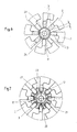
- Figure 2 shows one in contrast, already more closed position of the press jaws for exercise a holding function on the tampon blank.
- Figure 3 shows the pad press in State of the maximum press travel and thus also the maximum press pressure inside the tampon. The press jaws 2 are closed as far as possible.
- the pre-pressed Pushing the preform axially out of the tampon press is done in one last stage, which is shown in Figure 4, a partial opening or ventilation again the press jaws 2.
- the preform formed can by means of a Ram pushed out axially from the mold space formed by the press jaws become.
- the stepwise movement of the tampon press shown in FIGS. 1 to 4 is only in by turning the annular drive member 11 in Direction of the arrow 13 shown in Figures 1 and 2 generated.
- the arrow 14 in Figure 4 symbolizes the opening movement of the annular Drive elements 11 for the purpose of lifting the tampon press.
- the preform can be released by means of the plunger eject axially and insert into a downstream mold in which it maintains its final shape. This downstream mold is regularly called conically tapered sleeve formed in the preform on his final diameter is deformed.
- the angle ⁇ is shown, which of the as Transmission element serving pressure rod 9 with respect to the imaginary Connecting line 15 between the bearing axis 5 and press jaw 2 takes.
- this angle ⁇ is slightly larger than 90 °, in the positions according to Figures 3 and 4 slightly less than 90 °. This means, that at least at a time of the pressing process, the z. B. between the Positions according to Figures 2 and 3 is located, the direction R of the Push rod 9 on the press lever 4 exerted force essentially across, d. H. perpendicular to the imaginary connecting line 15 between Bearing axis 5 and press jaw 2 takes place.
- the part is slightly power transmission is smaller and sometimes slightly larger than 90 ° optimal, d. H. with moderate drive power for the ring-shaped Drive element 11 very high press forces on the press lever 4 and thus on the generate press jaw 2 arranged at right angles there. 3 is in the state the direction R is aligned almost directly with the tampon 1.
- Figure 5 shows the entire press tool in a greatly simplified Longitudinal section, being axially in front of the press tool and in alignment whose axis of rotation 12 is a plunger tool 17.
- the ram tool 17 is axially in the central direction in the direction designated by reference numeral 18 Molding space of the press tool formed from the press jaws 2 retractable.
- the plunger tool 17 takes the preform with it and conveys it into a mold downstream of the device, which is z. B. um can act a tapered sleeve towards its end, in which the Preform receives its final shape.
- the front end face 19 of the ram tool 17 that detects the preform has a star shape, which is described below with reference to FIG Figures 6 and 7 is explained in more detail.
- Figure 6 shows, compared to Figure 3, greatly enlarged the individual pressing jaws 2 the press blades 3 during the actual pressing process, d. H. at maximum closed press jaws.
- the preform is very strong in this state compacted, which is why it would not be possible to remove the preform in this state axially push out the fully closed press jaws. For this The reason is the pushing out by means of the plunger tool in the figure 4 shown release position of the tampon press.
- This release position is also in figure 7, namely greatly enlarged compared to Figure 4 and with additional Drawing of the end face 19 of the ram tool 17. It can be seen that the end face 19 consists of a central, circular pressure surface 20 and Additional pressure surfaces 21 projecting radially therefrom.
- the number of Additional pressure areas 21 is equal to the number of press cutting edges 3, moreover, viewed in the axial direction, the additional pressure surfaces 21 each on Gap 22 (FIG. 6) between two successive press cutting edges 3 aligned.
- the additional pressure surfaces 21 of the ram tool 17 thus "fit" exactly in these gaps 22 when the tampon press is aired Condition.
- the one defined by the outer edge 23 of the additional pressure areas 21 Diameter D is larger than that through the inner edge 24 (FIG. 6) Press cutting 3 defined press diameter d, both with respect to the press diameter d with the tampon press closed, as well as in relation to the press diameter d in the release position of the tampon press applies.
- the release position is that defined by the inner edge 24 of the cutting edges 3 Diameter D larger than their minimum pressing diameter.
- In this Release position is also the diameter of the central pressure surface 20 of the ram larger than the minimum pressing diameter d shown in FIG Press cutting 3.
- the additional pressure areas 21 are towards their outer edge 23 extended design. This leads to a further enlarged face of the Ram tool and thus to reduce the pressure on the Preform when pushing out and especially when starting Overcoming the static friction between the tampon and press blades.
Landscapes
- Health & Medical Sciences (AREA)
- Engineering & Computer Science (AREA)
- Vascular Medicine (AREA)
- Epidemiology (AREA)
- Biomedical Technology (AREA)
- Heart & Thoracic Surgery (AREA)
- Manufacturing & Machinery (AREA)
- Life Sciences & Earth Sciences (AREA)
- Animal Behavior & Ethology (AREA)
- General Health & Medical Sciences (AREA)
- Public Health (AREA)
- Veterinary Medicine (AREA)
- Absorbent Articles And Supports Therefor (AREA)
Abstract
Description
- Figur 1
- eine schematische Ansicht einer Vorrichtung zum Pressen eines Tampons mit Preßwerkzeugen in einer völlig geöffneten Stellung;
- Figur 2
- eine schematische Ansicht der Vorrichtung nach Figur 1 in einer geringfügig geschlossenen Haltestellung;
- Figur 3
- eine schematische Ansicht der Vorrichtung nach Figur 1 in maximal geschlossener Preßstellung;
- Figur 4
- eine schematische Ansicht der Vorrichtung nach Figur 1 in einer dem Preßvorgang folgenden Lüftstellung;
- Figur 5
- einen Längsschnitt durch die Vorrichtung zum Pressen eines Tampons mit einem axial vor dem Preßwerkzeug angeordneten Stößelwerkzeug;
- Figur 6
- in einer Detaildarstellung der Figur 3 die Preßbacken des Preßwerkzeuges in maximal geschlossener Preßstellung und
- Figur 7
- die Preßbacken nach Figur 6 in Lüftstellung einschließlich des darin axial eingefahrenen Stößelwerkzeuges.
- 1
- Tampon
- 2
- Preßbacken
- 3
- Preßschneide
- 4
- Preßhebel
- 5
- Lagerachse, Gelenk
- 6
- Stüztring
- 7
- Kreis
- 8
- Drehzapfen
- 9
- Druckstab
- 10
- Drehzapfen
- 11
- Antriebselement
- 12
- Drehachse
- 13
- Pfeil
- 14
- Pfeil
- 15
- Verbindungslinie
- 16
- Mittellinie
- 17
- Stößelwerkzeug
- 18
- Richtung
- 19
- Stirnfläche
- 20
- zentrale Druckfläche
- 21
- Zusatzdruckfläche
- 22
- Zwischenraum
- 23
- äußerer Rand
- 24
- innerer Rand
- α
- Winkel
- d
- Preßdurchmesser
- D
- Durchmesser
- R
- Richtung der Krafteinleitung
- u
- Abstand in Umfangsrichtung
Claims (4)
- Vorrichtung zum Herstellen eines Tampons aus einem im wesentlichen zylindrischen Rohling beliebiger Querschnittsform aus saugfähigem Material, mit einem Preßwerkzeug aus mehreren in bezug auf den zentral darin angeordneten Rohling (1) vor- und zurückbeweglichen Preßbacken (2), von denen über den Umfang des Rohlings (1) verteilt zumindest ein Teil der Preßbacken (2) mit hervorstehenden und den Rohling beim Preßvorgang mit Längsrillen versehenden Preßschneiden (3) versehen ist, und mit einem Stößelwerkzeug (17) zum axialen Ausschieben des gepreßten Vorformlings aus dem Preßwerkzeug,
dadurch gekennzeichnet, daß sich die wirksame Stirnfläche (19) des Stößelwerkzeuges (17) aus einer zentralen Druckfläche (20) und radial davon abstehenden Zusatzdruckflächen (21) zusammensetzt, daß der vom äußeren Rand (23) der Zusatzdruckflächen (21) definierte Durchmesser (D) größer ist als der durch den inneren Rand (24) der Preßschneiden (3) definierte minimale Preßdurchmesser (d), und daß jede Zusatzdruckfläche (21) auf einen der Zwischenräume (22) zwischen zwei aufeinander folgenden Preßschneiden (3) axial ausgerichtet ist. - Vorrichtung nach Anspruch 1, dadurch gekennzeichnet, daß die Preßbacken (2) in eine Lüftstellung einstellbar sind, in der der vom inneren Rand (24) der Preßschneiden (3) definierte Durchmesser (D) größer ist als deren minimaler Preßdurchmesser, und daß der Durchmesser der zentralen Druckfläche (20) des Stößelwerkzeuges (17) größer ist als der minimale Preßdurchmesser der Preßschneiden (3).
- Vorrichtung nach Anspruch 1 oder Anspruch 2, dadurch gekennzeichnet, daß die Preßbacken (2) in eine Lüftstellung einstellbar sind, in der der Umfangsabstand zwischen zwei aufeinander folgenden Preßschneiden (3) größer ist als deren Umfangsabstand (u) bei maximal geschlossenen Preßbacken (2), und daß bei maximal geschlossenen Preßbacken (2) die Breite der Zusatzdruckflächen (21) in Umfangsrichtung größer ist, als der Umfangsabstand (u) zwischen zwei aufeinander folgenden Preßschneiden (3).
- Vorrichtung nach einem der Ansprüche 1 bis 3, dadurch gekennzeichnet, daß die Zusatzdruckflächen (21) nach außenhin erweitert gestaltet sind.
Applications Claiming Priority (2)
| Application Number | Priority Date | Filing Date | Title |
|---|---|---|---|
| DE10151756 | 2001-10-19 | ||
| DE10151756A DE10151756C1 (de) | 2001-10-19 | 2001-10-19 | Vorrichtung zum Herstellen eines Tampons |
Publications (3)
| Publication Number | Publication Date |
|---|---|
| EP1304094A2 true EP1304094A2 (de) | 2003-04-23 |
| EP1304094A3 EP1304094A3 (de) | 2003-12-17 |
| EP1304094B1 EP1304094B1 (de) | 2011-03-30 |
Family
ID=7703110
Family Applications (1)
| Application Number | Title | Priority Date | Filing Date |
|---|---|---|---|
| EP02022404A Expired - Lifetime EP1304094B1 (de) | 2001-10-19 | 2002-10-04 | Vorrichtung zum Herstellen eines Tampons |
Country Status (4)
| Country | Link |
|---|---|
| EP (1) | EP1304094B1 (de) |
| AT (1) | ATE503447T1 (de) |
| DE (2) | DE10151756C1 (de) |
| ES (1) | ES2361731T3 (de) |
Cited By (1)
| Publication number | Priority date | Publication date | Assignee | Title |
|---|---|---|---|---|
| USD977632S1 (en) | 2020-02-26 | 2023-02-07 | Tampro Inc. | Tampon |
Families Citing this family (4)
| Publication number | Priority date | Publication date | Assignee | Title |
|---|---|---|---|---|
| US9072629B2 (en) | 2012-09-28 | 2015-07-07 | Kimberly-Clark Worldwide, Inc. | Shutter press compressor with movable jaws |
| US9078787B2 (en) | 2012-09-28 | 2015-07-14 | Kimberly-Clark Worldwide, Inc. | Shutter press compressor with shaping elements |
| US9072628B2 (en) | 2012-09-28 | 2015-07-07 | Kimberly-Clark Worldwide, Inc. | Shutter press compressor |
| CN109481151B (zh) * | 2018-12-18 | 2023-07-18 | 孙震 | 一种医用吸液棉生产装置及医用吸液棉生产系统 |
Citations (2)
| Publication number | Priority date | Publication date | Assignee | Title |
|---|---|---|---|---|
| DE9320358U1 (de) | 1993-04-10 | 1994-07-21 | Ruggli Ag Karl | Vorrichtung zur Herstellung von Tampons |
| EP1022004A1 (de) | 1999-01-23 | 2000-07-26 | Ruggli Projects AG | Vorrichtung zum Pressen eines Tampons, insbesondere für die Frauenhygiene |
Family Cites Families (3)
| Publication number | Priority date | Publication date | Assignee | Title |
|---|---|---|---|---|
| BE475102A (de) * | 1942-06-02 | |||
| CH613114A5 (en) * | 1977-03-04 | 1979-09-14 | Baumgartner Papiers Sa | Method for manufacturing a cellulose or cotton pad and pad obtained by this method |
| DE4304505C2 (de) * | 1993-02-15 | 1995-05-18 | Johnson & Johnson Gmbh | Tampon, insbesondere für die Frauenhygiene, sowie Verfahren und Vorrichtung zur Herstellung desselben |
-
2001
- 2001-10-19 DE DE10151756A patent/DE10151756C1/de not_active Expired - Fee Related
-
2002
- 2002-10-04 AT AT02022404T patent/ATE503447T1/de active
- 2002-10-04 EP EP02022404A patent/EP1304094B1/de not_active Expired - Lifetime
- 2002-10-04 ES ES02022404T patent/ES2361731T3/es not_active Expired - Lifetime
- 2002-10-04 DE DE50214983T patent/DE50214983D1/de not_active Expired - Lifetime
Patent Citations (2)
| Publication number | Priority date | Publication date | Assignee | Title |
|---|---|---|---|---|
| DE9320358U1 (de) | 1993-04-10 | 1994-07-21 | Ruggli Ag Karl | Vorrichtung zur Herstellung von Tampons |
| EP1022004A1 (de) | 1999-01-23 | 2000-07-26 | Ruggli Projects AG | Vorrichtung zum Pressen eines Tampons, insbesondere für die Frauenhygiene |
Cited By (2)
| Publication number | Priority date | Publication date | Assignee | Title |
|---|---|---|---|---|
| USD977632S1 (en) | 2020-02-26 | 2023-02-07 | Tampro Inc. | Tampon |
| USD1018839S1 (en) | 2020-02-26 | 2024-03-19 | Tampro Inc. | Tampon |
Also Published As
| Publication number | Publication date |
|---|---|
| EP1304094A3 (de) | 2003-12-17 |
| ATE503447T1 (de) | 2011-04-15 |
| ES2361731T3 (es) | 2011-06-21 |
| EP1304094B1 (de) | 2011-03-30 |
| DE50214983D1 (de) | 2011-05-12 |
| DE10151756C1 (de) | 2003-03-06 |
Similar Documents
| Publication | Publication Date | Title |
|---|---|---|
| DE2249762C3 (de) | Doppelt spreizender Dübel | |
| WO1995003766A2 (de) | Tampon sowie verfahren und vorrichtung zu seiner herstellung | |
| DE102012103017A1 (de) | Lagerung eines eine teilzylindrische Außenfläche aufweisenden Drehhebels gegenüber einem Druckstück | |
| DE19923752A1 (de) | Spanneinrichtung für Gegenstände, z. B. für zu bearbeitende Werkstücke | |
| DE2847736A1 (de) | Vorrichtung zum herstellen einer sicke am umfang eines hohlzylinders | |
| EP1017518A1 (de) | Drückwalzvorrichtung und verfahren zur herstellung von hohlrädern mit zwei innenverzahnungen | |
| EP1785233A2 (de) | Vorrichtung zur Demontage von Achsbauteilen | |
| EP1171260B1 (de) | Vorrichtung zum bruchtrennen eines werkstücks | |
| DE2804010A1 (de) | Brechstiftkupplung | |
| DE10151756C1 (de) | Vorrichtung zum Herstellen eines Tampons | |
| EP1003619A1 (de) | Verfahren zum herstellen eines schaltzahnrades, vorrichtung zur durchführung des verfahrens und nach dem verfahren hergestelltes schaltzahnrad | |
| DE10151758C2 (de) | Verfahren sowie Vorrichtung zum Herstellen eines Tampons | |
| EP0303002A1 (de) | Spannfutter | |
| DE19902643C1 (de) | Vorrichtung zum Pressen eines Tampons, insbesondere für die Frauenhygiene | |
| DE3410967A1 (de) | Bohrkopf zum tieflochbohren | |
| EP3610988B1 (de) | Pressvorrichtung mit zentrierter bolzenfixierung | |
| DE2519416C3 (de) | Honwerkzeug für Bohrungen | |
| EP1250199B1 (de) | Verfahren und umformwerkzeug zur zylinderrohrherstellung mittels fliesspressen | |
| AT392755B (de) | Hydraulische presse | |
| DE4025745C2 (de) | ||
| DE3529671C1 (de) | Wirkteller für eine Bäckereimaschine | |
| EP2165785A1 (de) | Vorrichtung und Verfahren zur Herstellung von Längsnuten in zylindrischen Werkstücken | |
| DE19946508C2 (de) | Verfahren zum Herstellen einer Welle mit durchmessergrößerem Flansch | |
| DE2644680C3 (de) | Einrichtung an einer Presse für die Verformung zylindrischer Rohlinge | |
| DE4025773C1 (en) | Clamping irregular shaped workpieces - involves plates made of hard flexible material |
Legal Events
| Date | Code | Title | Description |
|---|---|---|---|
| PUAI | Public reference made under article 153(3) epc to a published international application that has entered the european phase |
Free format text: ORIGINAL CODE: 0009012 |
|
| AK | Designated contracting states |
Designated state(s): AT BE BG CH CY CZ DE DK EE ES FI FR GB GR IE IT LI LU MC NL PT SE SK TR |
|
| AX | Request for extension of the european patent |
Extension state: AL LT LV MK RO SI |
|
| PUAL | Search report despatched |
Free format text: ORIGINAL CODE: 0009013 |
|
| AK | Designated contracting states |
Kind code of ref document: A3 Designated state(s): AT BE BG CH CY CZ DE DK EE ES FI FR GB GR IE IT LI LU MC NL PT SE SK TR |
|
| AX | Request for extension of the european patent |
Extension state: AL LT LV MK RO SI |
|
| 17P | Request for examination filed |
Effective date: 20040221 |
|
| AKX | Designation fees paid |
Designated state(s): AT BE BG CH CY CZ DE DK EE ES FI FR GB GR IE IT LI LU MC NL PT SE SK TR |
|
| 17Q | First examination report despatched |
Effective date: 20081118 |
|
| GRAP | Despatch of communication of intention to grant a patent |
Free format text: ORIGINAL CODE: EPIDOSNIGR1 |
|
| GRAS | Grant fee paid |
Free format text: ORIGINAL CODE: EPIDOSNIGR3 |
|
| GRAA | (expected) grant |
Free format text: ORIGINAL CODE: 0009210 |
|
| AK | Designated contracting states |
Kind code of ref document: B1 Designated state(s): AT BE BG CH CY CZ DE DK EE ES FI FR GB GR IE IT LI LU MC NL PT SE SK TR |
|
| REG | Reference to a national code |
Ref country code: GB Ref legal event code: FG4D Free format text: NOT ENGLISH |
|
| REG | Reference to a national code |
Ref country code: CH Ref legal event code: EP |
|
| REG | Reference to a national code |
Ref country code: CH Ref legal event code: NV Representative=s name: ABP PATENT NETWORK SWISS GMBH |
|
| REG | Reference to a national code |
Ref country code: IE Ref legal event code: FG4D |
|
| REF | Corresponds to: |
Ref document number: 50214983 Country of ref document: DE Date of ref document: 20110512 Kind code of ref document: P |
|
| REG | Reference to a national code |
Ref country code: DE Ref legal event code: R096 Ref document number: 50214983 Country of ref document: DE Effective date: 20110512 |
|
| RAP2 | Party data changed (patent owner data changed or rights of a patent transferred) |
Owner name: RUGGLI PROJECTS AG |
|
| REG | Reference to a national code |
Ref country code: ES Ref legal event code: FG2A Ref document number: 2361731 Country of ref document: ES Kind code of ref document: T3 Effective date: 20110621 |
|
| REG | Reference to a national code |
Ref country code: NL Ref legal event code: VDEP Effective date: 20110330 |
|
| PG25 | Lapsed in a contracting state [announced via postgrant information from national office to epo] |
Ref country code: GR Free format text: LAPSE BECAUSE OF FAILURE TO SUBMIT A TRANSLATION OF THE DESCRIPTION OR TO PAY THE FEE WITHIN THE PRESCRIBED TIME-LIMIT Effective date: 20110701 Ref country code: SE Free format text: LAPSE BECAUSE OF FAILURE TO SUBMIT A TRANSLATION OF THE DESCRIPTION OR TO PAY THE FEE WITHIN THE PRESCRIBED TIME-LIMIT Effective date: 20110330 |
|
| PG25 | Lapsed in a contracting state [announced via postgrant information from national office to epo] |
Ref country code: FI Free format text: LAPSE BECAUSE OF FAILURE TO SUBMIT A TRANSLATION OF THE DESCRIPTION OR TO PAY THE FEE WITHIN THE PRESCRIBED TIME-LIMIT Effective date: 20110330 Ref country code: CY Free format text: LAPSE BECAUSE OF FAILURE TO SUBMIT A TRANSLATION OF THE DESCRIPTION OR TO PAY THE FEE WITHIN THE PRESCRIBED TIME-LIMIT Effective date: 20110330 |
|
| REG | Reference to a national code |
Ref country code: IE Ref legal event code: FD4D |
|
| PG25 | Lapsed in a contracting state [announced via postgrant information from national office to epo] |
Ref country code: PT Free format text: LAPSE BECAUSE OF FAILURE TO SUBMIT A TRANSLATION OF THE DESCRIPTION OR TO PAY THE FEE WITHIN THE PRESCRIBED TIME-LIMIT Effective date: 20110801 Ref country code: EE Free format text: LAPSE BECAUSE OF FAILURE TO SUBMIT A TRANSLATION OF THE DESCRIPTION OR TO PAY THE FEE WITHIN THE PRESCRIBED TIME-LIMIT Effective date: 20110330 |
|
| PG25 | Lapsed in a contracting state [announced via postgrant information from national office to epo] |
Ref country code: SK Free format text: LAPSE BECAUSE OF FAILURE TO SUBMIT A TRANSLATION OF THE DESCRIPTION OR TO PAY THE FEE WITHIN THE PRESCRIBED TIME-LIMIT Effective date: 20110330 |
|
| PG25 | Lapsed in a contracting state [announced via postgrant information from national office to epo] |
Ref country code: NL Free format text: LAPSE BECAUSE OF FAILURE TO SUBMIT A TRANSLATION OF THE DESCRIPTION OR TO PAY THE FEE WITHIN THE PRESCRIBED TIME-LIMIT Effective date: 20110330 |
|
| PG25 | Lapsed in a contracting state [announced via postgrant information from national office to epo] |
Ref country code: IE Free format text: LAPSE BECAUSE OF FAILURE TO SUBMIT A TRANSLATION OF THE DESCRIPTION OR TO PAY THE FEE WITHIN THE PRESCRIBED TIME-LIMIT Effective date: 20110330 |
|
| PLBE | No opposition filed within time limit |
Free format text: ORIGINAL CODE: 0009261 |
|
| STAA | Information on the status of an ep patent application or granted ep patent |
Free format text: STATUS: NO OPPOSITION FILED WITHIN TIME LIMIT |
|
| PG25 | Lapsed in a contracting state [announced via postgrant information from national office to epo] |
Ref country code: DK Free format text: LAPSE BECAUSE OF FAILURE TO SUBMIT A TRANSLATION OF THE DESCRIPTION OR TO PAY THE FEE WITHIN THE PRESCRIBED TIME-LIMIT Effective date: 20110330 |
|
| 26N | No opposition filed |
Effective date: 20120102 |
|
| REG | Reference to a national code |
Ref country code: DE Ref legal event code: R097 Ref document number: 50214983 Country of ref document: DE Effective date: 20120102 |
|
| BERE | Be: lapsed |
Owner name: RUGGLI PROJECTS A.G. Effective date: 20111031 |
|
| PG25 | Lapsed in a contracting state [announced via postgrant information from national office to epo] |
Ref country code: MC Free format text: LAPSE BECAUSE OF NON-PAYMENT OF DUE FEES Effective date: 20111031 Ref country code: IT Free format text: LAPSE BECAUSE OF FAILURE TO SUBMIT A TRANSLATION OF THE DESCRIPTION OR TO PAY THE FEE WITHIN THE PRESCRIBED TIME-LIMIT Effective date: 20110330 |
|
| PG25 | Lapsed in a contracting state [announced via postgrant information from national office to epo] |
Ref country code: BE Free format text: LAPSE BECAUSE OF NON-PAYMENT OF DUE FEES Effective date: 20111031 |
|
| PGFP | Annual fee paid to national office [announced via postgrant information from national office to epo] |
Ref country code: GB Payment date: 20121023 Year of fee payment: 11 |
|
| PGFP | Annual fee paid to national office [announced via postgrant information from national office to epo] |
Ref country code: FR Payment date: 20130214 Year of fee payment: 11 |
|
| PG25 | Lapsed in a contracting state [announced via postgrant information from national office to epo] |
Ref country code: LU Free format text: LAPSE BECAUSE OF NON-PAYMENT OF DUE FEES Effective date: 20111004 |
|
| PG25 | Lapsed in a contracting state [announced via postgrant information from national office to epo] |
Ref country code: BG Free format text: LAPSE BECAUSE OF FAILURE TO SUBMIT A TRANSLATION OF THE DESCRIPTION OR TO PAY THE FEE WITHIN THE PRESCRIBED TIME-LIMIT Effective date: 20110630 |
|
| REG | Reference to a national code |
Ref country code: CH Ref legal event code: NV Representative=s name: ABP PATENT NETWORK AG, CH |
|
| PG25 | Lapsed in a contracting state [announced via postgrant information from national office to epo] |
Ref country code: TR Free format text: LAPSE BECAUSE OF FAILURE TO SUBMIT A TRANSLATION OF THE DESCRIPTION OR TO PAY THE FEE WITHIN THE PRESCRIBED TIME-LIMIT Effective date: 20110330 |
|
| GBPC | Gb: european patent ceased through non-payment of renewal fee |
Effective date: 20131004 |
|
| PG25 | Lapsed in a contracting state [announced via postgrant information from national office to epo] |
Ref country code: GB Free format text: LAPSE BECAUSE OF NON-PAYMENT OF DUE FEES Effective date: 20131004 |
|
| REG | Reference to a national code |
Ref country code: FR Ref legal event code: ST Effective date: 20140630 |
|
| PG25 | Lapsed in a contracting state [announced via postgrant information from national office to epo] |
Ref country code: FR Free format text: LAPSE BECAUSE OF NON-PAYMENT OF DUE FEES Effective date: 20131031 |
|
| PGFP | Annual fee paid to national office [announced via postgrant information from national office to epo] |
Ref country code: CZ Payment date: 20140930 Year of fee payment: 13 Ref country code: ES Payment date: 20141010 Year of fee payment: 13 Ref country code: DE Payment date: 20141023 Year of fee payment: 13 Ref country code: CH Payment date: 20141010 Year of fee payment: 13 |
|
| PGFP | Annual fee paid to national office [announced via postgrant information from national office to epo] |
Ref country code: AT Payment date: 20141022 Year of fee payment: 13 |
|
| PG25 | Lapsed in a contracting state [announced via postgrant information from national office to epo] |
Ref country code: CZ Free format text: LAPSE BECAUSE OF NON-PAYMENT OF DUE FEES Effective date: 20151004 |
|
| REG | Reference to a national code |
Ref country code: DE Ref legal event code: R119 Ref document number: 50214983 Country of ref document: DE |
|
| REG | Reference to a national code |
Ref country code: CH Ref legal event code: PL |
|
| REG | Reference to a national code |
Ref country code: AT Ref legal event code: MM01 Ref document number: 503447 Country of ref document: AT Kind code of ref document: T Effective date: 20151004 |
|
| PG25 | Lapsed in a contracting state [announced via postgrant information from national office to epo] |
Ref country code: DE Free format text: LAPSE BECAUSE OF NON-PAYMENT OF DUE FEES Effective date: 20160503 Ref country code: CH Free format text: LAPSE BECAUSE OF NON-PAYMENT OF DUE FEES Effective date: 20151031 Ref country code: LI Free format text: LAPSE BECAUSE OF NON-PAYMENT OF DUE FEES Effective date: 20151031 |
|
| PG25 | Lapsed in a contracting state [announced via postgrant information from national office to epo] |
Ref country code: AT Free format text: LAPSE BECAUSE OF NON-PAYMENT OF DUE FEES Effective date: 20151004 |
|
| REG | Reference to a national code |
Ref country code: ES Ref legal event code: FD2A Effective date: 20161125 |
|
| PG25 | Lapsed in a contracting state [announced via postgrant information from national office to epo] |
Ref country code: ES Free format text: LAPSE BECAUSE OF NON-PAYMENT OF DUE FEES Effective date: 20151005 |