EP1303701B1 - Pumpe - Google Patents
Pumpe Download PDFInfo
- Publication number
- EP1303701B1 EP1303701B1 EP01955226A EP01955226A EP1303701B1 EP 1303701 B1 EP1303701 B1 EP 1303701B1 EP 01955226 A EP01955226 A EP 01955226A EP 01955226 A EP01955226 A EP 01955226A EP 1303701 B1 EP1303701 B1 EP 1303701B1
- Authority
- EP
- European Patent Office
- Prior art keywords
- suction
- flow
- jet chamber
- jet
- fluid
- Prior art date
- Legal status (The legal status is an assumption and is not a legal conclusion. Google has not performed a legal analysis and makes no representation as to the accuracy of the status listed.)
- Expired - Lifetime
Links
- 210000003734 kidney Anatomy 0.000 claims description 49
- 239000012530 fluid Substances 0.000 claims description 46
- 238000011144 upstream manufacturing Methods 0.000 claims description 12
- 238000012986 modification Methods 0.000 claims description 8
- 230000004048 modification Effects 0.000 claims description 8
- 238000013461 design Methods 0.000 claims description 6
- 230000007423 decrease Effects 0.000 claims 2
- 238000000926 separation method Methods 0.000 claims 1
- 238000005422 blasting Methods 0.000 description 36
- 230000001133 acceleration Effects 0.000 description 5
- 241000252254 Catostomidae Species 0.000 description 4
- 230000015572 biosynthetic process Effects 0.000 description 3
- 238000000034 method Methods 0.000 description 3
- 238000004458 analytical method Methods 0.000 description 2
- 238000000576 coating method Methods 0.000 description 2
- 210000001331 nose Anatomy 0.000 description 2
- XLYOFNOQVPJJNP-UHFFFAOYSA-N water Substances O XLYOFNOQVPJJNP-UHFFFAOYSA-N 0.000 description 2
- 230000002146 bilateral effect Effects 0.000 description 1
- 239000003795 chemical substances by application Substances 0.000 description 1
- 239000011248 coating agent Substances 0.000 description 1
- 238000010276 construction Methods 0.000 description 1
- 230000002950 deficient Effects 0.000 description 1
- 230000001419 dependent effect Effects 0.000 description 1
- 238000011161 development Methods 0.000 description 1
- 230000018109 developmental process Effects 0.000 description 1
- 230000000694 effects Effects 0.000 description 1
- 238000005516 engineering process Methods 0.000 description 1
- 210000001061 forehead Anatomy 0.000 description 1
- 238000009472 formulation Methods 0.000 description 1
- 238000009499 grossing Methods 0.000 description 1
- 238000004519 manufacturing process Methods 0.000 description 1
- 239000000203 mixture Substances 0.000 description 1
- 238000011176 pooling Methods 0.000 description 1
- 230000001737 promoting effect Effects 0.000 description 1
- 230000003716 rejuvenation Effects 0.000 description 1
- 238000007788 roughening Methods 0.000 description 1
- 238000012360 testing method Methods 0.000 description 1
- 238000012549 training Methods 0.000 description 1
Images


Classifications
-
- F—MECHANICAL ENGINEERING; LIGHTING; HEATING; WEAPONS; BLASTING
- F04—POSITIVE - DISPLACEMENT MACHINES FOR LIQUIDS; PUMPS FOR LIQUIDS OR ELASTIC FLUIDS
- F04C—ROTARY-PISTON, OR OSCILLATING-PISTON, POSITIVE-DISPLACEMENT MACHINES FOR LIQUIDS; ROTARY-PISTON, OR OSCILLATING-PISTON, POSITIVE-DISPLACEMENT PUMPS
- F04C15/00—Component parts, details or accessories of machines, pumps or pumping installations, not provided for in groups F04C2/00 - F04C14/00
- F04C15/06—Arrangements for admission or discharge of the working fluid, e.g. constructional features of the inlet or outlet
-
- F—MECHANICAL ENGINEERING; LIGHTING; HEATING; WEAPONS; BLASTING
- F01—MACHINES OR ENGINES IN GENERAL; ENGINE PLANTS IN GENERAL; STEAM ENGINES
- F01C—ROTARY-PISTON OR OSCILLATING-PISTON MACHINES OR ENGINES
- F01C21/00—Component parts, details or accessories not provided for in groups F01C1/00 - F01C20/00
- F01C21/10—Outer members for co-operation with rotary pistons; Casings
-
- F—MECHANICAL ENGINEERING; LIGHTING; HEATING; WEAPONS; BLASTING
- F04—POSITIVE - DISPLACEMENT MACHINES FOR LIQUIDS; PUMPS FOR LIQUIDS OR ELASTIC FLUIDS
- F04C—ROTARY-PISTON, OR OSCILLATING-PISTON, POSITIVE-DISPLACEMENT MACHINES FOR LIQUIDS; ROTARY-PISTON, OR OSCILLATING-PISTON, POSITIVE-DISPLACEMENT PUMPS
- F04C2/00—Rotary-piston machines or pumps
- F04C2/30—Rotary-piston machines or pumps having the characteristics covered by two or more groups F04C2/02, F04C2/08, F04C2/22, F04C2/24 or having the characteristics covered by one of these groups together with some other type of movement between co-operating members
- F04C2/34—Rotary-piston machines or pumps having the characteristics covered by two or more groups F04C2/02, F04C2/08, F04C2/22, F04C2/24 or having the characteristics covered by one of these groups together with some other type of movement between co-operating members having the movement defined in groups F04C2/08 or F04C2/22 and relative reciprocation between the co-operating members
- F04C2/344—Rotary-piston machines or pumps having the characteristics covered by two or more groups F04C2/02, F04C2/08, F04C2/22, F04C2/24 or having the characteristics covered by one of these groups together with some other type of movement between co-operating members having the movement defined in groups F04C2/08 or F04C2/22 and relative reciprocation between the co-operating members with vanes reciprocating with respect to the inner member
- F04C2/3441—Rotary-piston machines or pumps having the characteristics covered by two or more groups F04C2/02, F04C2/08, F04C2/22, F04C2/24 or having the characteristics covered by one of these groups together with some other type of movement between co-operating members having the movement defined in groups F04C2/08 or F04C2/22 and relative reciprocation between the co-operating members with vanes reciprocating with respect to the inner member the inner and outer member being in contact along one line or continuous surface substantially parallel to the axis of rotation
- F04C2/3442—Rotary-piston machines or pumps having the characteristics covered by two or more groups F04C2/02, F04C2/08, F04C2/22, F04C2/24 or having the characteristics covered by one of these groups together with some other type of movement between co-operating members having the movement defined in groups F04C2/08 or F04C2/22 and relative reciprocation between the co-operating members with vanes reciprocating with respect to the inner member the inner and outer member being in contact along one line or continuous surface substantially parallel to the axis of rotation the surfaces of the inner and outer member, forming the working space, being surfaces of revolution
Definitions
- the invention relates to a pump for conveying a fluid, in particular a vane pump, with a housed in a housing conveyor, a formed in the housing supply channel for the fluid, which is in the intake the conveyor extends and upstream in one of the conveyor Blasting chamber opens, and with an injector, which is used to convey the fluid serves, radiates with a jet nozzle in the blasting chamber while under high Pressurized, fluid in the emerging from the feed channel in the blasting chamber Injecting fluid and thereby entrained or accelerated, wherein the blasting chamber via a suction channel with at least two suction kidneys of the conveyor fluidly connected.
- Pumps of the generic type are used for example in power steering systems and promote a special oil to support the steering wheel of a To cause motor vehicle applied steering force.
- these are vane pumps, which are provided from outside the pump Reservoir, for example, from an external tank, suck in oil.
- Such Pumps are usually equipped with a flow control valve, over the oil off the high pressure area - pressure side - in the intake - suction side - the Pump can be routed. From a certain pump speed and at a fixed flow rate, the flow control valve opens a discharge hole, can escape through the high pressure oil. The oil gets into the Intake area of the conveyor.
- valve piston under possibly high pressure on Valve piston at high speed in the jet nozzle flowing valve jet basically runs obliquely and therefore unsuitable symmetrically formed channels are.
- the present invention is therefore based on the object, a pump of the generic type Design and develop such a way that cavitations and thus occurring in the pump noise largely by simple design means are avoided.
- the pump of the invention solves the voranstahende task by the features of claim 1.
- ski-like guide is approximately matched to the beam angle of the fluid or tuned to this is.
- the impact area or the hill-like Guide in the blasting chamber initially serving to bundle the flow Subordinate Queritessverjünguhg the flow path.
- This Cross-sectional taper could in turn be a redirection and finally a split be arranged downstream of the two suction channels, which by the deflection forced directional change influence on the subsequent division of the Has flow in the two suction channels.
- Guiding devices may be provided, for example, the respective walls the flow path or the suction channels can be assigned.
- the diversion and division of the entire flow has to be done in any case so that in the two suction channels results in about the same volume flow, which in turn on the two suction channels to the inlet of the Saugnieren passes.
- the blasting chamber could have two separate suction channels each be flow connected at least one Saugniere or suction chamber.
- the blasting chamber divides into two independent suction channels which in turn fluidly connect the blasting chamber with the suction kidneys.
- the flow-influencing means designed such that to the two suckers - on the respective suction channels - a largely same volume flow results.
- the flow of the fluid influencing means such as those provided in the blasting chamber Schanzenähnliche guide and in particular the targeted coordination of Formation of walls, "noses" or the like. Corresponding facilities are also conceivable in the suction channels.
- the flow from the blasting chamber into the influence both suction channels by the configuration of the flow path.
- the flow in the two suction channels is at least slightly deflected. This deflection serves to influence the directed into the suction channels Volumetric flow, so that even so far a the flow rate gleichze touchde Dividing the flow in the two suction channels is made into it.
- Flow influencing agent in particular cross-sectional modifications and / or Guiding devices, be provided to last there influence on the sucked kidneys to take the resulting volume flow.
- Cross-sectional tapers, others Umienkungen or even a labyrinth-like configuration of the suction channel are adequate means for influencing the flow, more precisely the flow velocity, the prevailing pressure and thus the volume flow.
- the blasting chamber could be at a single suction channel with at least two successively arranged Saugnieren fluidly connected be. Also in this respect could already previously referred to as the impact area Einström Anlagen or the ski-like guide first a for bundling the flow serving cross-sectional taper of the flow path be downstream, with the flow cross-section to the first Saugniere out steadily, swinging or even reducing in stages. The bundling of the flow leads to an acceleration of the fluid up to the first Saugniere.
- the flow cross-section between the first suction kidney and the second suction kidney at least equal to the flow area in front of the first suckling kidney. It should be ensured that the flow rates in the two Suck suckers into it at least largely evenly, so that a uniform loading of the suction kidneys takes place. Behind the second suction kidney could be formed a deflection causing baffle, so that thereby a deflection and thus a repeated BdinLINung the volume flow takes place into the second suction kidney.
- the suction channel could be immediate behind the second Saugnjere end with the deflection wall provided there.
- the suction channel in the area between the two suckers or after the rearmost in the flow direction suction kidney the blasting chamber or with the region of the suction channel in front of the first suction kidney be fluidly connected directly or via a bypass.
- Flow connection can be the pressure conditions and thus the flow rates affect before the respective suckling, so that in so far a Adjustment can take place with respect to the volume flows.
- the flow of the fluid in particular in the suction kidneys directed volumetric flow, through more far-reaching measures, namely by a modification of the inner wall of the blasting chamber and / or of the suction channel or the suction channels.
- the surfaces could affect the flow Have structures and / or coatings.
- the Inner walls - depending on requirements - be surface treated, with a roughening the surface to an increase of the flow resistance and a smoothing or smooth coating of the surface to a reduction of the flow resistance and thus leads to an acceleration of the flow.
- the housing on one side by a front side Housing cover and on the other side if necessary by a bearing flange can be completed.
- the both sides of the Conveyor beam formed at least largely in the housing cover and optionally incorporated in the bearing flange.
- the flow paths formed on both sides of the actual housing are identical or different, depending on the by the housing or the housing cover and / or the bearing flange specified Geometries and requirements.
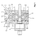
- Fig. 1 shows a simplified representation of a generic type pump in one cut side view, which is here in concrete to a vane pump with a rotation group 1 or conveyor not described in detail here is.
- a rotation group 1 With regard to the particular embodiment of such a rotation group 1, reference is made, by way of example only, to DE 41 38 516 A1.
- the pump shown here comprises - as essential components - a housing. 2 and a conveyer accommodated in the housing 2, which is thereby is the already mentioned rotation group 1.
- Forehead is on one side a housing 2 final housing cover 3 and on the other side - on the housing cover 3 opposite side - a to the housing 2 subsequent bearing flange 4 is provided.
- the actual housing 2 together with the housing cover 3 and bearing flange 4 could be referred to as housing in the broadest sense become.
- an outwardly acting Seal 5, 6 arranged, wherein the relative to the housing cover 3 acting Seal 5 is inserted in a groove 8 formed in the end face 7 of the housing 2 is.
- the seal 6 is the bearing flange 4 assigned or inserted into a groove 9 incorporated in the bearing flange 4.
- the Groove 9 could also be incorporated into the end face 10 of the housing 2.
- FIGS 1 and 2 clearly show that the suction area, i. to the suction area 12, a supply channel 13 for the fluid extends. Furthermore, one is for Promoting the fluid injector device provided, which is similar to a water jet pump is working. This injector device 14 injects in front of a flow control valve piston high pressure fluid at the control edge of the valve piston upstream at a high speed in one of the conveyors 1 Blasting chamber 15, and there in the emerging from the supply channel 13 fluid and accelerates the fluid thereby or tears the fluid with.
- the supply channel 13 opens on both sides of the conveyor 1, each with a sub-channel 16 in a - separate - blasting chamber 15, wherein the injector 14th radiates on both sides, so that in each of the two jet chambers 15, a jet nozzle 17th the injector 14 is directed.
- the jet nozzles 17 may optionally be shortened or omitted, so as not to obstruct the beam.
- Figs. 1 and 2 show together that the injector 14 centrally over the Conveyor 1 is arranged.
- the jet nozzles 17 are aligned in this way, that the injected via the jet nozzle 17 at high speed fluid impinges on the fluid to be accelerated in approximately its flow direction, so that an acceleration of the fluid coming from the tank is again favored.
- the Fluid from the system passes through the supply channel 13, the fluid from the pump passes through a valve bore 14 and discharge holes 14a to the two Jet nozzles 17.
- Fig. 1 reveals further that the formed on both sides of the conveyor 1 Blasting chamber 15 largely in the housing cover 3 on one side and is incorporated in the bearing flange 4 on the other side.
- the jet nozzles 17 are here orthogonal to the outlet of the feed channel 13 opposite Wall 18 of the housing cover 3 on the one hand and on the outlet of the Supply channel 13 opposite wall 19 of the bearing flange 4 on the other Side directed, but can also obliquely on the outlet of the supply channel 13 opposite wall 18 of the housing cover 3 on the one hand and on the outlet of the feed channel 13 opposite wall 19 of the bearing flange 4 be directed on the other side, namely to swirl effectively to avoid.
- Figs. 2 and 3 can be further seen that the supply channel 13 on both sides of Conveyor 1, each with a sub-channel 16 in one of the conveyor. 1 upstream blasting chamber 15 opens and that the injector 14 on two sides with one jet nozzle 17 in each of the two jet chambers 15 radiates.
- the blasting chamber 15 is over two Suction channels 20 each having a suction kidney or suction chamber, not shown in the figures the conveyor 1 fluidly connected.
- Fig. 3 further shows that the flow from the Strahfhunt 15 in the two suction channels 20 through the embodiment the flow path is deflected, wherein the deflection of the flow serves to influence the directed into the suction channels 20 volume flow.
- the two suction channels 20 on both sides of the blasting chamber 15 substantially formed symmetrically.
- the impact area in the blasting chamber 15 is a cross-sectional taper 24 of the flow path serving to bundle the flow downstream.
- the cross-sectional tapering 24 is followed by a deflection 23 and division 25 into the two suction channels 20, wherein the formation of opposite Noses 24a, 24b is of particular importance.
- Fig. 3 reveals further that in the suction channels 20 and immediately before the Saugnigren further flow influencing means are provided, namely Sectional Modifications and Guiding Devices 20.
- Figs. 4, 5 and 6 show cross-sections through the article of Fig. 3. So lets Fig. 4 in particular the formed in the blasting chamber 15 shot-like Detect guide 22 through which the beam 21 without the emergence of unnecessary Swirling is redirected or directed.
- Fig. 5 shows in cross section the suction channel 20, in the region of the suction kidney, also with appropriate guide 26, which is an integral part of the wall.
- the situation is similar with the illustration in Fig. 6, the suction passage 20 approximately in Longitudinal section shows.
- a suction channel refers to a housing cover 3, in the at least a part of the blasting chamber 15 and a singular suction channel 20 incorporated is.
- the beam 21 hits a ramp-like guide 22, whereby the beam 21 is influenced in its flow direction.
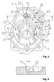
- FIG. 7 shows particularly clearly that the blasting chamber 15 has a single Suction channel 20 with two arranged one behind the other, not shown in the figures Saugnieren is fluidly connected, where there are only those directed to the suction kidneys Inlets 27 are indicated.
- the impact area or the ski-like guide 22 in the blasting chamber 15 is a cross-sectional taper used to bundle the flow 24 of the flow path and the suction channel 20 downstream.
- Fig. 7 further allows recognize that the flow cross-section to the first Saugniere or to whose inlet 27 is continuously reduced, whereby an acceleration of the flow takes place.
- the suction channel 20 in the exemplary embodiment chosen here directly before the inlet 27 to the suction kidneys, more influencing the flow Means provided, which are further guide means 28.
- Immediately before the suckers are also ski jump-like guiding devices 28 formed to facilitate the introduction into the inlet 27.
- the guiding devices 28 are integral parts of the housing cover. 3
- Fig. 7 is further indicated that the flow cross-section between the first Saugniere and the second Saugniere is lower (for example, by a flattened gutter) than the flow cross-section in front of the first suction kidney or before their inlet 27. Furthermore, the flow cross-section is reduced between the first suction kidney and the second suction kidney or between the two Inlets 27 at least slightly.
Landscapes
- Engineering & Computer Science (AREA)
- Mechanical Engineering (AREA)
- General Engineering & Computer Science (AREA)
- Rotary Pumps (AREA)
- Details And Applications Of Rotary Liquid Pumps (AREA)
- External Artificial Organs (AREA)
Description
- Fig. 1
- in einer schematischen Seitenansicht, geschnitten, ein Ausführungsbeispiel einer gattungsgemäßen Pumpe,
- Fig. 2
- in einer schematischen Seitenansicht, geschnitten und vergrößert, den Gegenstand aus Fig. 1 ohne Gehäusedeckel, ohne Lagerflansch und ohne Fördereinrichtung,
- Fig. 3
- in einer schematischen Innenansicht einen Lagerflansch mit zwei Saugkanälen,
- Fig. 4
- den Gegenstand aus Fig. 3 in einer geschnittenen Darstellung entlang der Linie A-A,
- Fig. 5
- den Gegenstand aus Fig. 3, teilweise, in einer geschnittenen Darstellung entlang der Linie B-B,
- Fig. 6
- den Gegenstand aus Fig. 3, teilweise, in einer geschnittenen Darstellung entlang der bogenförmigen Linie C-C und
- Fig. 7
- in einer schematischen Innenansicht einen Gehäusedeckel, in dessen Wandung einer singulärer Saugkanal ausgebildet ist.
Claims (13)
- Pumpe zum Fördern eines Fluids, insbesondere Flügelzellenpumpe, mit einer in einem Gehäuse (2) untergebrachten Fördereinrichtung (1), einem im Gehäuse (2) ausgebildeten Zufuhrkanal (13) für das Fluid, der mit dem Ansaugbereich der Fördereinrichtung (1) verbunden ist und in eine der Fördereinrichtung (1) vorgelagerte Strahlkammer (15) mündet, und mit einer Injektoreinrichtung (14), die zum Fördern des Fluids dient, mit einer Strahldüse (17) in die mindestens Strahlkammer (15) abstrahlt und dabei unter hoher Geschwindigkeit strömendes Fluid in das aus dem Zufuhrkanal (13) in die Strahlkammer (15) austretende Fluid einspritzt und dieses dadurch mitreißt bzw. beschleunigt, wobei die Strahlkammer (15) über mindestens einen Saugkanal (20) mit mindestens zwei Saugnieren der Fördereinrichtung (1) strömungsverbunden ist,
dadurch gekennzeichnet, dass im Einströmbereich der Strahlkammer (15) und/oder im Saugkanal (20) die Strömung des Fluids beeinflussende Mittel vorgesehen sind, die einen zumindest weitgehend gleichen Volumenstrom in die Saugnieren gewährleisten und dass die Mittel als schanzenähnliche Leiteinrichtung im Aufprallbereich der der Strahldüse (17) gegenüberliegenden Wandung (18, 19) ausgebildet ist. - Pumpe, nach Anspruch 1, dadurch gekennzeichnet, dass der Zufuhrkanal (13) beidseits der Fördereinrichtung (1) mit jeweils einem Teilkanal (16) in jeweils eine der Fördereinrichtung (1) vorgelagerte Strahlkammer (15) mündet und dass die Injektoreinrichtung (14) zweiseitig mit je einer Strahldüse (17) in jede der beiden Strahlkammern (15) abstrahlt.
- Pumpe, nach Anspruch 1 oder 2, dadurch gekennzeichnet, dass der in die Strahlkammer (15) gerichtete Strahl in Strömungsrichtung schräg auf die der Strahldüse (17) gegenüberliegende Wandung der Strahlkammer (15) auftrifft.
- Pumpe, nach einem der Ansprüche 1 bis 3, dadurch gekennzeichnet, dass die Strahlkammer (15) über zwei Saugkanäle (20) mit jeweils mindestens einer Saugniere bzw. Saugkammer strömungsverbunden ist, wobei die Strömung (23) von der Strahlkammer (15) in die beiden Saugkanäle (20) durch die Ausgestaltung des Strömungspfads gebündelt und danach zumindest geringfügig umgelenkt wird und wobei die Umlenkung der Strömung (23) zur Beeinflussung des in die Saugkanäle (20) gerichteten Volumenstroms bzw. zur Beeinflussung der Aufteilung des Volumenstroms dient.
- Pumpe, nach Anspruch 4, dadurch gekennzeichnet, dass die Saugkanäle (20) beidseits der Strahlkammer (15) (rechts, links und stromabwärts) im Wesentlichen symmetrisch ausgebildet sind.
- Pumpe, nach einem der Ansprüche 3 bis 5, dadurch gekennzeichnet, dass dem Aufprallbereich in der Strahlkammer (15) eine zur Bündelung der Strömung (23) dienende Querschnittsverjüngung (24) des Strömungspfads nachgeordnet ist, wobei dem Aufprallbereich in der Strahlkammer (15), vorzugsweise der Querschnittsverjüngung (24), eine Umlenkung (25) und Aufteilung in die beiden Saugkanäle (20) folgt.
- Pumpe, nach einem der Ansprüche 1 bis 6, dadurch gekennzeichnet, dass in den Saugkanälen (20) und/oder unmittelbar vor den Saugnieren weitere die Strömung (23) beeinflussende Mittel, insbesondere Querschnittsmodifikationen, Leiteinrichtungen (26) oder Kombination von Querschnittsmodifikationen und Leiteinrichtungen (26), vorgesehen sind.
- Pumpe, nach einem der Ansprüche 1 bis 7, ggf. nach einem der Ansprüche 5 bis 8, dadurch gekennzeichnet, dass die Strahlkammer (15) über einen Saugkanal (20) mit mindestens zwei hintereinander angeordneten Saugnieren strömungsverbunden ist, wobei dem Aufprallbereich in der Strahlkammer (15) eine zur Bündelung der Strömung (23) dienende Querschnittsverjüngung (24) des Strömungspfads nachgeordnet ist und wobei sich der Strömungsquerschnitt vorzugsweise zur ersten Saugniere hin stetig verringert.
- Pumpe, nach Anspruch 8, dadurch gekennzeichnet, dass in dem Saugkanal (20), insbesondere unmittelbar vor den Saugnieren, weitere die Strömung (23) in Richtung in die Nieren hinein beeinflussende Mittel, insbesondere Leiteinrichtungen (28), vorgesehen sind, wobei unmittelbar vor den Saugnieren schanzenähnliche Leiteinrichtungen (28) ausgebildet sind und wobei die Leiteinrichtungen (28) vorzugsweise integrale Bestandteile des Gehäuses (2, 3, 4) und/oder des Flansches und/oder des Deckels sind.
- Pumpe, nach Anspruch 8 oder 9, dadurch gekennzeichnet, dass der Strömungsquerschnitt zwischen der ersten Saugniere und der zweiten Saugniere geringer ist als der Strömungsquerschnitt vor der ersten Saugniere, wobei sich der Strömungsquerschnitt zwischen der ersten Saugniere und der zweiten Saugniere vorzugsweise stetig verringert.
- Pumpe, nach einem der Ansprüche 8 bis 10, dadurch gekennzeichnet, dass hinter der zweiten Saugniere eine eine Umlenkung verursachende Prallwand (29) ausgebildet ist, wobei der Saugkanal (20) im Bereich zwischen den beiden Saugnieren oder nach der in Strömungsrichtung hintersten Saugniere mit der Strahlkammer (15) oder dem Bereich des Saugkanals (20) vor der ersten Saugniere unmittelbar oder über einen Bypass strömungsverbunden ist.
- Pumpe, nach einem der Ansprüche 1 bis 11, dadurch gekennzeichnet, dass die Innenwandungen der Strahlkammer (15) und/oder des Saugkanals (20) zur Beeinflussung der Strömung (23) oberflächenbehandelt ist/sind.
- Pumpe, nach einem der Ansprüche 1 bis 12, wobei das Gehäuse auf der einen Seite durch einen stirnseitigen Gehäusedeckel (3) und auf der anderen Seite gegebenenfalls durch einen Lagerflansch (4) abgeschlossen ist, dadurch gekennzeichnet, dass die beidseits der Fördereinrichtung (1) ausgebildete Strahlkammer (15) zumindest weitgehend in den Gehäusedeckel (3) und vorzugsweise in den Lagerflansch (4) eingearbeitet ist.
Applications Claiming Priority (3)
| Application Number | Priority Date | Filing Date | Title |
|---|---|---|---|
| DE20022423U DE20022423U1 (de) | 2000-07-27 | 2000-07-27 | Pumpe |
| DE20022423U | 2000-07-27 | ||
| PCT/DE2001/002497 WO2002010591A2 (de) | 2000-07-27 | 2001-07-05 | Pumpe |
Publications (2)
| Publication Number | Publication Date |
|---|---|
| EP1303701A2 EP1303701A2 (de) | 2003-04-23 |
| EP1303701B1 true EP1303701B1 (de) | 2005-08-31 |
Family
ID=7950761
Family Applications (1)
| Application Number | Title | Priority Date | Filing Date |
|---|---|---|---|
| EP01955226A Expired - Lifetime EP1303701B1 (de) | 2000-07-27 | 2001-07-05 | Pumpe |
Country Status (6)
| Country | Link |
|---|---|
| US (1) | US6837689B2 (de) |
| EP (1) | EP1303701B1 (de) |
| JP (1) | JP4859329B2 (de) |
| AU (1) | AU2001277472A1 (de) |
| DE (1) | DE50107304D1 (de) |
| WO (1) | WO2002010591A2 (de) |
Families Citing this family (2)
| Publication number | Priority date | Publication date | Assignee | Title |
|---|---|---|---|---|
| US7766915B2 (en) * | 2004-02-27 | 2010-08-03 | Jackson Roger P | Dynamic fixation assemblies with inner core and outer coil-like member |
| JP4253592B2 (ja) | 2004-01-06 | 2009-04-15 | オリンパス株式会社 | 液浸対物レンズ、蛍光分析装置および倒立型顕微鏡。 |
Family Cites Families (23)
| Publication number | Priority date | Publication date | Assignee | Title |
|---|---|---|---|---|
| US3359913A (en) * | 1965-10-22 | 1967-12-26 | Chrysler Corp | Hydraulic pump |
| US3366065A (en) * | 1967-01-03 | 1968-01-30 | Chrysler Corp | Supercharging of balanced hydraulic pump |
| JPS5669491A (en) * | 1979-11-13 | 1981-06-10 | Kayaba Ind Co Ltd | Vane pump |
| JPS59190489A (ja) * | 1983-04-13 | 1984-10-29 | Atsugi Motor Parts Co Ltd | ベ−ンポンプ |
| JPS59215981A (ja) * | 1983-05-23 | 1984-12-05 | Nippon Soken Inc | ベ−ン型油圧ポンプ |
| JPH0660640B2 (ja) * | 1985-09-09 | 1994-08-10 | 清之 堀井 | 管路に螺旋流体流を生成させる装置 |
| US4971252A (en) * | 1987-12-24 | 1990-11-20 | Yoshino Kogyosho Co., Ltd. | Nozzle cap |
| JP2638987B2 (ja) | 1988-08-30 | 1997-08-06 | アイシン精機株式会社 | 油圧駆動ファンシステム用油圧ポンプ |
| JP2555545Y2 (ja) * | 1991-03-07 | 1997-11-26 | 自動車機器株式会社 | ベーンポンプ |
| DE4122433C2 (de) | 1991-07-06 | 1994-03-24 | Luk Fahrzeug Hydraulik | Pumpe |
| DE4138516A1 (de) * | 1991-11-23 | 1993-05-27 | Luk Fahrzeug Hydraulik | Pumpe |
| JPH074397A (ja) * | 1993-03-10 | 1995-01-10 | 正志 ▲土▼田 | 水噴流ポンプ装置の構造 |
| JPH08112247A (ja) * | 1994-10-14 | 1996-05-07 | Olympus Optical Co Ltd | 内視鏡 |
| JPH08200300A (ja) * | 1995-01-30 | 1996-08-06 | Mitsubishi Heavy Ind Ltd | 空気混入式水流発生装置 |
| DE59609992D1 (de) * | 1995-09-14 | 2003-01-30 | Luk Fahrzeug Hydraulik | Pumpe |
| DE19637224A1 (de) * | 1996-09-13 | 1998-03-12 | Luk Fahrzeug Hydraulik | Pumpe |
| JPH10153200A (ja) * | 1996-11-22 | 1998-06-09 | Asahi Glass Co Ltd | 流体吸引装置 |
| JPH09296800A (ja) * | 1997-01-16 | 1997-11-18 | Sadamu Katayama | 高速渦巻噴流ポンプ |
| JPH10295812A (ja) * | 1997-05-01 | 1998-11-10 | Terumo Corp | 薬液供給具 |
| DE19927400A1 (de) * | 1998-06-24 | 1999-12-30 | Luk Fahrzeug Hydraulik | Hydraulische Fördereinrichtung |
| WO2000009888A2 (de) * | 1998-08-13 | 2000-02-24 | Luk Fahrzeug-Hydraulik Gmbh & Co. Kg | Pumpe |
| DE19836628A1 (de) * | 1998-08-13 | 2000-02-17 | Luk Fahrzeug Hydraulik | Pumpe |
| US6270385B1 (en) * | 1999-09-07 | 2001-08-07 | Bombardier Motor Corporation Of America | Pump jet rotor housing modification for noise signature spectral control |
-
2001
- 2001-07-05 EP EP01955226A patent/EP1303701B1/de not_active Expired - Lifetime
- 2001-07-05 JP JP2002516486A patent/JP4859329B2/ja not_active Expired - Lifetime
- 2001-07-05 DE DE50107304T patent/DE50107304D1/de not_active Expired - Lifetime
- 2001-07-05 WO PCT/DE2001/002497 patent/WO2002010591A2/de not_active Ceased
- 2001-07-05 AU AU2001277472A patent/AU2001277472A1/en not_active Abandoned
-
2003
- 2003-01-27 US US10/352,313 patent/US6837689B2/en not_active Expired - Lifetime
Also Published As
| Publication number | Publication date |
|---|---|
| JP2004505209A (ja) | 2004-02-19 |
| DE50107304D1 (de) | 2005-10-06 |
| US20030138330A1 (en) | 2003-07-24 |
| US6837689B2 (en) | 2005-01-04 |
| JP4859329B2 (ja) | 2012-01-25 |
| WO2002010591A3 (de) | 2002-04-18 |
| EP1303701A2 (de) | 2003-04-23 |
| WO2002010591A2 (de) | 2002-02-07 |
| AU2001277472A1 (en) | 2002-02-13 |
Similar Documents
| Publication | Publication Date | Title |
|---|---|---|
| DE4310761C2 (de) | Strahlpumpe | |
| EP0301310B1 (de) | Axialkolbenmaschine in Schrägscheiben- oder Schrägachsenbauart mit Schlitzsteuerung und Druckausgleichskanälen | |
| DE102011076443B4 (de) | Rückschlagventil für Sprühdüse und Düsenrohr | |
| DE19504079A1 (de) | Strömungspumpe zum Fördern von Kraftstoff aus einem Vorratsbehälter zur Brennkraftmaschine eines Kraftfahrzeuges | |
| DE2531200C3 (de) | Regelbare Kolbenpumpe mit Erosionsschutzeinsatz in der gemeinsamen EinlaB/AuslaB-Leitung | |
| DE10239558B4 (de) | Außenzahnradpumpe mit Druckfluidvorladung | |
| EP2543442A2 (de) | Sprühdüse und Verfahren zum Erzeugen wenigstens eines rotierenden Sprühstrahls | |
| EP0347581B1 (de) | Einspritzpumpe für Brennkraftmaschinen | |
| WO2014009018A1 (de) | Kaltgasspritzpistole mit pulverinjektor | |
| EP3031531B1 (de) | Flüssigkeitsstrahl-verschlussdüse | |
| EP1303701B1 (de) | Pumpe | |
| DE9210497U1 (de) | Ejektorpumpe | |
| DE102011084405B4 (de) | Saugaufgeladene Pumpe zum Fördern einer Flüssigkeit | |
| DE19802137C1 (de) | Zahnradpumpe | |
| WO2011101121A1 (de) | Dosierpumpe | |
| DE102009050143A1 (de) | Verdrängerpumpe | |
| DE10037080A1 (de) | Pumpe | |
| EP1323926B1 (de) | Pumpe | |
| DE20022423U1 (de) | Pumpe | |
| DE4340011B4 (de) | Peripheralpumpe, insbesondere zum Fördern von Kraftstoff aus einem Vorratstank zur Brennkraftmaschine eines Kraftfahrzeuges | |
| DE4438696A1 (de) | Flügelzellenpumpe | |
| DE19836628A1 (de) | Pumpe | |
| DE29823903U1 (de) | Pumpe | |
| DE10229794C1 (de) | Einstrahlzähler für Flüssigkeiten | |
| EP1567706B1 (de) | Vorrichtung zum aufbringen einer ber die arbeitsbreite glei chm ssig dicken fl ssigkeitsschicht auf eine warenbahn |
Legal Events
| Date | Code | Title | Description |
|---|---|---|---|
| PUAI | Public reference made under article 153(3) epc to a published international application that has entered the european phase |
Free format text: ORIGINAL CODE: 0009012 |
|
| 17P | Request for examination filed |
Effective date: 20021127 |
|
| AK | Designated contracting states |
Designated state(s): AT BE CH CY DE DK ES FI FR GB GR IE IT LI LU MC NL PT SE TR |
|
| AX | Request for extension of the european patent |
Extension state: AL LT LV MK RO SI |
|
| 17Q | First examination report despatched |
Effective date: 20040301 |
|
| RBV | Designated contracting states (corrected) |
Designated state(s): AT BE CH CY DE FR GB IT LI |
|
| GRAP | Despatch of communication of intention to grant a patent |
Free format text: ORIGINAL CODE: EPIDOSNIGR1 |
|
| GRAS | Grant fee paid |
Free format text: ORIGINAL CODE: EPIDOSNIGR3 |
|
| GRAA | (expected) grant |
Free format text: ORIGINAL CODE: 0009210 |
|
| AK | Designated contracting states |
Kind code of ref document: B1 Designated state(s): DE FR GB IT |
|
| RBV | Designated contracting states (corrected) |
Designated state(s): DE FR GB IT |
|
| REG | Reference to a national code |
Ref country code: GB Ref legal event code: FG4D Free format text: NOT ENGLISH |
|
| REF | Corresponds to: |
Ref document number: 50107304 Country of ref document: DE Date of ref document: 20051006 Kind code of ref document: P |
|
| GBT | Gb: translation of ep patent filed (gb section 77(6)(a)/1977) | ||
| ET | Fr: translation filed | ||
| PLBE | No opposition filed within time limit |
Free format text: ORIGINAL CODE: 0009261 |
|
| STAA | Information on the status of an ep patent application or granted ep patent |
Free format text: STATUS: NO OPPOSITION FILED WITHIN TIME LIMIT |
|
| 26N | No opposition filed |
Effective date: 20060601 |
|
| REG | Reference to a national code |
Ref country code: DE Ref legal event code: R082 Ref document number: 50107304 Country of ref document: DE Representative=s name: RAUSCH, GABRIELE, DIPL.-PHYS. DR.RER.NAT., DE Ref country code: DE Ref legal event code: R079 Ref document number: 50107304 Country of ref document: DE Free format text: PREVIOUS MAIN CLASS: F04C0015020000 Ipc: F04C0015060000 |
|
| REG | Reference to a national code |
Ref country code: DE Ref legal event code: R079 Ref document number: 50107304 Country of ref document: DE Free format text: PREVIOUS MAIN CLASS: F04C0015020000 Ipc: F04C0015060000 Effective date: 20140910 Ref country code: DE Ref legal event code: R082 Ref document number: 50107304 Country of ref document: DE Representative=s name: RAUSCH, GABRIELE, DIPL.-PHYS. DR.RER.NAT., DE Effective date: 20140910 Ref country code: DE Ref legal event code: R081 Ref document number: 50107304 Country of ref document: DE Owner name: MAGNA POWERTRAIN BAD HOMBURG GMBH, DE Free format text: FORMER OWNER: IXETIC BAD HOMBURG GMBH, 61352 BAD HOMBURG, DE Effective date: 20140910 |
|
| PGFP | Annual fee paid to national office [announced via postgrant information from national office to epo] |
Ref country code: IT Payment date: 20140731 Year of fee payment: 14 |
|
| PG25 | Lapsed in a contracting state [announced via postgrant information from national office to epo] |
Ref country code: IT Free format text: LAPSE BECAUSE OF NON-PAYMENT OF DUE FEES Effective date: 20150705 |
|
| REG | Reference to a national code |
Ref country code: FR Ref legal event code: PLFP Year of fee payment: 16 |
|
| PGFP | Annual fee paid to national office [announced via postgrant information from national office to epo] |
Ref country code: GB Payment date: 20160721 Year of fee payment: 16 |
|
| PGFP | Annual fee paid to national office [announced via postgrant information from national office to epo] |
Ref country code: FR Payment date: 20160721 Year of fee payment: 16 |
|
| GBPC | Gb: european patent ceased through non-payment of renewal fee |
Effective date: 20170705 |
|
| REG | Reference to a national code |
Ref country code: FR Ref legal event code: ST Effective date: 20180330 |
|
| PG25 | Lapsed in a contracting state [announced via postgrant information from national office to epo] |
Ref country code: GB Free format text: LAPSE BECAUSE OF NON-PAYMENT OF DUE FEES Effective date: 20170705 |
|
| PG25 | Lapsed in a contracting state [announced via postgrant information from national office to epo] |
Ref country code: FR Free format text: LAPSE BECAUSE OF NON-PAYMENT OF DUE FEES Effective date: 20170731 |
|
| REG | Reference to a national code |
Ref country code: DE Ref legal event code: R082 Ref document number: 50107304 Country of ref document: DE Representative=s name: HOFFMANN - EITLE PATENT- UND RECHTSANWAELTE PA, DE |
|
| REG | Reference to a national code |
Ref country code: DE Ref legal event code: R082 Ref document number: 50107304 Country of ref document: DE Representative=s name: HOFFMANN - EITLE PATENT- UND RECHTSANWAELTE PA, DE Ref country code: DE Ref legal event code: R081 Ref document number: 50107304 Country of ref document: DE Owner name: HANON SYSTEMS EFP DEUTSCHLAND GMBH, DE Free format text: FORMER OWNER: MAGNA POWERTRAIN BAD HOMBURG GMBH, 61352 BAD HOMBURG, DE |
|
| PGFP | Annual fee paid to national office [announced via postgrant information from national office to epo] |
Ref country code: DE Payment date: 20200721 Year of fee payment: 20 |
|
| REG | Reference to a national code |
Ref country code: DE Ref legal event code: R071 Ref document number: 50107304 Country of ref document: DE |