EP1302802A2 - Kameramodul für ein Mobilfunkgerät - Google Patents
Kameramodul für ein Mobilfunkgerät Download PDFInfo
- Publication number
- EP1302802A2 EP1302802A2 EP02102421A EP02102421A EP1302802A2 EP 1302802 A2 EP1302802 A2 EP 1302802A2 EP 02102421 A EP02102421 A EP 02102421A EP 02102421 A EP02102421 A EP 02102421A EP 1302802 A2 EP1302802 A2 EP 1302802A2
- Authority
- EP
- European Patent Office
- Prior art keywords
- camera module
- lenses
- lens
- lens system
- communication device
- Prior art date
- Legal status (The legal status is an assumption and is not a legal conclusion. Google has not performed a legal analysis and makes no representation as to the accuracy of the status listed.)
- Withdrawn
Links
Images
Classifications
-
- G—PHYSICS
- G02—OPTICS
- G02B—OPTICAL ELEMENTS, SYSTEMS OR APPARATUS
- G02B13/00—Optical objectives specially designed for the purposes specified below
- G02B13/001—Miniaturised objectives for electronic devices, e.g. portable telephones, webcams, PDAs, small digital cameras
- G02B13/0015—Miniaturised objectives for electronic devices, e.g. portable telephones, webcams, PDAs, small digital cameras characterised by the lens design
-
- G—PHYSICS
- G02—OPTICS
- G02B—OPTICAL ELEMENTS, SYSTEMS OR APPARATUS
- G02B9/00—Optical objectives characterised both by the number of the components and their arrangements according to their sign, i.e. + or -
- G02B9/04—Optical objectives characterised both by the number of the components and their arrangements according to their sign, i.e. + or - having two components only
- G02B9/10—Optical objectives characterised both by the number of the components and their arrangements according to their sign, i.e. + or - having two components only one + and one - component
Definitions
- the present invention relates to a camera module for a Mobile radio device consisting of a lens system and a Sensor.
- the object of the present invention is a camera module of the type mentioned at the beginning, which is characterized by a lightweight, small and simple construction.
- This object is inventively for the above Camera module solved in that the lens system from two identically constructed in the beam path in mirror image to each other arranged convex-concave lenses, the concave Areas of the lenses face each other and between the an aperture is arranged on both lenses.
- the first that is the outer lens
- the aperture can be used for the subsequent one Lens, which acts as a diverging lens and which for the Image on the sensor surface of the sensor is responsible, the opening angle should be kept small so that there are none Distortions in the edge area result.
- An expedient embodiment of the camera module according to the invention is characterized in that the material of the lenses Is plastic. This results in low costs for the camera module according to the invention.
- the drawing shows schematically the structure of an inventive Camera module.
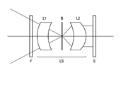
- the camera module according to the invention exists essentially from a filter F, a lens system LS and a sensor S.
- the sensor S may, for example, be a known one Act CCD facility. Any can in front of the lens system LS commercially available filter F may be provided.
- the lens system LS consists of the lens L1, the lens L2 and the aperture B.
- the lenses L1 and L2 are identical convex-concave lenses that mirror each other are arranged.
- the lens L1 acts as a converging lens, while the lens L2 acts as a diverging lens.
- the lens L2 which is the actual image on the sensor surface generated by the converging lens L1 and Panel B provided a small virtual image it only needs a small opening angle, which causes distortions in the edge area in the final image be avoided even though the camera module itself over has a large opening angle.
Landscapes
- Physics & Mathematics (AREA)
- General Physics & Mathematics (AREA)
- Optics & Photonics (AREA)
- Studio Devices (AREA)
Abstract
Description
Claims (3)
- Kameramodul für ein Mobilfunkgerät, bestehend aus einem Linsensystem und einem Sensor,
dadurch gekennzeichnet ,dass das Linsensystem (LS) aus zwei gleich aufgebauten im Strahlengang spiegelbildlich zueinander angeordneten Konvex-Konkav-Linsen (L1, L2) besteht, wobei die konkaven Flächen der Linsen (L1, L2) einander gegenüber liegen und zwischen den beiden Linsen (L1, L2) eine Blende (B) angeordnet ist. - Kameramodul nach Anspruch 1,
dadurch gekennzeichnet, dass das Material der Linsen (L1, L2) Kunststoff ist. - Kameramodul nach einem der vorherigen Ansprüche,
dadurch gekennzeichnet ,dass vor dem Linsensystem (LS) eine Filteranordnung (F) vorgesehen ist.
Applications Claiming Priority (2)
| Application Number | Priority Date | Filing Date | Title |
|---|---|---|---|
| DE10149747 | 2001-10-09 | ||
| DE2001149747 DE10149747C2 (de) | 2001-10-09 | 2001-10-09 | Kameramodul für ein Mobilfunkgerät |
Publications (2)
| Publication Number | Publication Date |
|---|---|
| EP1302802A2 true EP1302802A2 (de) | 2003-04-16 |
| EP1302802A3 EP1302802A3 (de) | 2004-03-03 |
Family
ID=7701893
Family Applications (1)
| Application Number | Title | Priority Date | Filing Date |
|---|---|---|---|
| EP02102421A Withdrawn EP1302802A3 (de) | 2001-10-09 | 2002-10-07 | Kameramodul für ein Mobilfunkgerät |
Country Status (2)
| Country | Link |
|---|---|
| EP (1) | EP1302802A3 (de) |
| DE (1) | DE10149747C2 (de) |
Cited By (1)
| Publication number | Priority date | Publication date | Assignee | Title |
|---|---|---|---|---|
| EP1441248A1 (de) * | 2003-01-22 | 2004-07-28 | Milestone Co., Ltd | Objektiv zur Bildaufnahme |
Families Citing this family (1)
| Publication number | Priority date | Publication date | Assignee | Title |
|---|---|---|---|---|
| DE102017011352B4 (de) | 2017-12-07 | 2020-01-30 | Friedrich Grimm | Kameramoduleinheit für Digitalaufnahmen |
Family Cites Families (5)
| Publication number | Priority date | Publication date | Assignee | Title |
|---|---|---|---|---|
| JPS5659216A (en) * | 1979-10-18 | 1981-05-22 | Olympus Optical Co Ltd | Standard lens with wide angle of view |
| US5689376A (en) * | 1995-04-24 | 1997-11-18 | Eastman Kodak Company | Two element optical system, a camera using it and method of making the camera |
| JP3566460B2 (ja) * | 1996-06-28 | 2004-09-15 | 株式会社トミー | 光学装置 |
| DE29722657U1 (de) * | 1997-12-31 | 1998-05-07 | Jesberger Joerg | Handy mit integrierter Kamera |
| JP2000227547A (ja) * | 1999-02-05 | 2000-08-15 | Fuji Photo Film Co Ltd | 撮影レンズおよびこれを用いるカメラ |
-
2001
- 2001-10-09 DE DE2001149747 patent/DE10149747C2/de not_active Expired - Fee Related
-
2002
- 2002-10-07 EP EP02102421A patent/EP1302802A3/de not_active Withdrawn
Cited By (2)
| Publication number | Priority date | Publication date | Assignee | Title |
|---|---|---|---|---|
| EP1441248A1 (de) * | 2003-01-22 | 2004-07-28 | Milestone Co., Ltd | Objektiv zur Bildaufnahme |
| US6888686B2 (en) | 2003-01-22 | 2005-05-03 | Satoshi Do | Lens for image pickup |
Also Published As
| Publication number | Publication date |
|---|---|
| DE10149747C2 (de) | 2003-10-09 |
| EP1302802A3 (de) | 2004-03-03 |
| DE10149747A1 (de) | 2003-04-30 |
Similar Documents
| Publication | Publication Date | Title |
|---|---|---|
| DE2718804C3 (de) | Vorrichtung zur PositionierungskontroUe von Patienten und/oder Bestrahlungsquellen | |
| EP3339950B1 (de) | Ellipsenartige blende für ein kameraobjektiv bzw. für eine photo- oder filmkamera | |
| DE4318526C2 (de) | Bildeingabevorrichtung | |
| DE112005003221T5 (de) | Steuersystem und -verfahren für einen Cursor in einer Anzeigevorrichtung | |
| WO2020052874A1 (de) | Kalibrierungssystem und kalibrierungsverfahren für eine fahrzeug-erfassungseinrichtung | |
| DE2855496C2 (de) | Vorrichtung zum Verschieben und/oder Kippen des Objektivs einer Spiegelreflexkamera | |
| DE3211281A1 (de) | Verfahren zum feststellen der scharfeinstellung optischer geraete | |
| CH683649A5 (de) | Automatisch arbeitendes fotografisches Kopiergerät mit einer Vorrichtung zum Maskieren. | |
| DE202017106567U1 (de) | Kamerasystem einschliesslich Objektiv mit Vergrösserungsgradient | |
| DE69418111T2 (de) | Steuergerät und Steuerverfahren für Bildeingabevorrichtung | |
| WO2001081995A1 (de) | Vorrichtung in abbildenden optischen systemen einer laufbild-filmaufnahmekamera | |
| WO2001008409A1 (de) | Mobiles bildtelefon | |
| EP3932282B1 (de) | Spülgerät mit bilderfassungseinrichtung | |
| DE10149747C2 (de) | Kameramodul für ein Mobilfunkgerät | |
| DE69628806T2 (de) | Kamera mit variabler Ablenkung | |
| EP1237362B1 (de) | Videokamera und Adapter für eine Videokamera | |
| DE1522325A1 (de) | Filmkassette und Kamera mit Belichtungsmess- bzw. Steuereinrichtung | |
| DE3247820C2 (de) | ||
| DE3785554T2 (de) | Programmverschluss für Kamera mit Objektivverschluss und Vorrichtung zur Verhinderung des Photographierens von Fremdstoffen auf dem Objektiv. | |
| DE3879598T2 (de) | Elektronischer bildabtaster mit variabler steuerung des kontrastes. | |
| DE3828485A1 (de) | Bildfernsprechgeraet | |
| DE202004020330U1 (de) | Vorrichtung zur Überprüfung von Randbereichen flächiger Elemente | |
| DE60022975T2 (de) | Fotoapparat mit automatischem Fokussierungsgerät | |
| DE69311621T2 (de) | Blenden-Mechanismus | |
| DE2627364C2 (de) | Blendenvorrichtung |
Legal Events
| Date | Code | Title | Description |
|---|---|---|---|
| PUAI | Public reference made under article 153(3) epc to a published international application that has entered the european phase |
Free format text: ORIGINAL CODE: 0009012 |
|
| AK | Designated contracting states |
Designated state(s): AT BE BG CH CY CZ DE DK EE ES FI FR GB GR IE IT LI LU MC NL PT SE SK TR |
|
| AX | Request for extension of the european patent |
Extension state: AL LT LV MK RO SI |
|
| PUAL | Search report despatched |
Free format text: ORIGINAL CODE: 0009013 |
|
| AK | Designated contracting states |
Kind code of ref document: A3 Designated state(s): AT BE BG CH CY CZ DE DK EE ES FI FR GB GR IE IT LI LU MC NL PT SE SK TR |
|
| AX | Request for extension of the european patent |
Extension state: AL LT LV MK RO SI |
|
| RIC1 | Information provided on ipc code assigned before grant |
Ipc: 7G 02B 9/08 A Ipc: 7G 02B 13/16 B |
|
| 17P | Request for examination filed |
Effective date: 20040405 |
|
| 17Q | First examination report despatched |
Effective date: 20040506 |
|
| AKX | Designation fees paid |
Designated state(s): AT BE BG CH CY CZ DE DK EE ES FI FR GB GR IE IT LI LU MC NL PT SE SK TR |
|
| RAP1 | Party data changed (applicant data changed or rights of an application transferred) |
Owner name: BENQ MOBILE GMBH & CO. OHG |
|
| 19U | Interruption of proceedings before grant |
Effective date: 20070101 |
|
| 19W | Proceedings resumed before grant after interruption of proceedings |
Effective date: 20070702 |
|
| 19W | Proceedings resumed before grant after interruption of proceedings |
Effective date: 20090803 |
|
| RAP1 | Party data changed (applicant data changed or rights of an application transferred) |
Owner name: PALM, INC. |
|
| RAP1 | Party data changed (applicant data changed or rights of an application transferred) |
Owner name: HEWLETT-PACKARD DEVELOPMENT COMPANY, L.P. |
|
| RAP1 | Party data changed (applicant data changed or rights of an application transferred) |
Owner name: QUALCOMM INCORPORATED |
|
| STAA | Information on the status of an ep patent application or granted ep patent |
Free format text: STATUS: EXAMINATION IS IN PROGRESS |
|
| STAA | Information on the status of an ep patent application or granted ep patent |
Free format text: STATUS: THE APPLICATION IS DEEMED TO BE WITHDRAWN |
|
| 18D | Application deemed to be withdrawn |
Effective date: 20170221 |