US5689376A - Two element optical system, a camera using it and method of making the camera - Google Patents
Two element optical system, a camera using it and method of making the camera Download PDFInfo
- Publication number
- US5689376A US5689376A US08/427,552 US42755295A US5689376A US 5689376 A US5689376 A US 5689376A US 42755295 A US42755295 A US 42755295A US 5689376 A US5689376 A US 5689376A
- Authority
- US
- United States
- Prior art keywords
- optical system
- lens
- radius
- lens elements
- biaspheric
- Prior art date
- Legal status (The legal status is an assumption and is not a legal conclusion. Google has not performed a legal analysis and makes no representation as to the accuracy of the status listed.)
- Expired - Lifetime
Links
Images


Classifications
-
- G—PHYSICS
- G02—OPTICS
- G02B—OPTICAL ELEMENTS, SYSTEMS OR APPARATUS
- G02B9/00—Optical objectives characterised both by the number of the components and their arrangements according to their sign, i.e. + or -
- G02B9/04—Optical objectives characterised both by the number of the components and their arrangements according to their sign, i.e. + or - having two components only
- G02B9/06—Optical objectives characterised both by the number of the components and their arrangements according to their sign, i.e. + or - having two components only two + components
- G02B9/08—Optical objectives characterised both by the number of the components and their arrangements according to their sign, i.e. + or - having two components only two + components arranged about a stop
-
- G—PHYSICS
- G02—OPTICS
- G02B—OPTICAL ELEMENTS, SYSTEMS OR APPARATUS
- G02B13/00—Optical objectives specially designed for the purposes specified below
- G02B13/18—Optical objectives specially designed for the purposes specified below with lenses having one or more non-spherical faces, e.g. for reducing geometrical aberration
Definitions
- This invention relates to optical systems comprising two lens components suitable for use in photographic devices having curved image surfaces.
- U.S. Pat. No. 3,006,248 by W. R. Linke discloses an objective lens system having a cylindrical image surface that comprises two meniscus lens elements. This lens system has a field of view of about 62 degrees and an aperture of about F/8. The disclosed lens system, "while of the symmetrical type is not completely symmetrical.” This lens system has no aspheric surfaces.
- optical systems including two different asymmetrically located lens elements.
- U.S. Pat. Nos. 4,932,764 and 5,000,552 disclose a two-element lens system suitable for use in inexpensive cameras having a curved image surface, such as single-use cameras.
- This lens system utilizes two meniscus lens elements arranged around the aperture stop.
- the lens system is characterized by very good aberration correction, considering that only two lens elements are used.
- These lens systems have F-numbers F/8 and F/11 and accommodate a field of view of at least 62 and 75 degrees respectively, without the use of aspheric surfaces.
- U.S. Pat. No. 5,067,803 also discloses a two-element lens system for use in photographic cameras. This patent also uses two meniscus lens elements arranged around a central aperture stop. The disclosed lens system utilizes a single aspheric surface on either one or both of the lens elements, but nevertheless performs at relatively slow (i.e. narrow) aperture, i.e. F/13.8.
- U.S. Pat. No. 5,327,291 also discloses a two component objective lens system.
- the disclosed lens system utilizes a single aspheric surface on each of the two lens elements.
- This lens system is designed for a flat image plane (i.e. surface) and has a field of view that does not exceed 60 degrees.
- the two lens element camera objectives are often designed to provide an F/number of F/11 or more. It is advantageous for camera objectives (i.e., taking lenses) to have a wide-angle, fast lens system with a superior performance. However, that is difficult to accomplish with only two lens elements. Thus, notwithstanding the variety of objective lens systems which have been previously proposed, there still exists a need for lens systems of simple construction which can be produced at low cost.
- Applicant's invention addresses this need and represents a further improvement in two element lens systems for camera objectives (i.e. taking lenses).
- An object of the present invention is to produce an improved two-component or two element lens system with curved image surfaces.
- an optical system for use in a low-cost camera having an image surface curved toward the optical system, the optical system comprising only two single lens components and an aperture stop located therebetween, one of said lens components being biaspheric, the optical system having a curved image corresponding substantially (in its long dimension) to the curved image surface of the camera through a full field angle of at least 62.5 degrees and preferably 70 degrees or more.
- a method of making a single-use camera from previously used single-use camera parts comprises the steps of: (A) providing a camera body having a film cassette chamber, (B) supporting in the camera body previously used single-use camera parts including a viewfinder, a shutter mechanism, and an optical system including only two lens elements, one of said lens elements being biaspheric, each of said lens elements having an index of refraction of at least 1.45; and (C) loading an unexposed roll of fill into the fill cassette chamber of the camera body.
- a single-use camera from previously used camera parts comprises: a camera body having a film cassette chamber, the camera body supporting previously used single-use camera parts including an optical system comprising only two lens elements, one of the lens elements being biaspheric, and a shutter located between the lens elements, the optical system being adapted for imaging on a curved film plane; a shutter mechanism, and a viewfinder; and an unexposed roll of fill mounted in the fill cassette chamber of the camera body.
- the lens system has a significantly improved optical performance while simultaneously being able to provide a wide angle coverage (from 0 to nearly 80 degrees) and a high numerical aperture (such as F/8 for example). More specifically, we discovered that having one biaspheric lens component in a two component lens system similar to the one described herein unexpectedly provides significantly better optical aberration correction then a similar lens system having two aspheric surfaces, where each of the aspheric surfaces corresponds to a different lens element.
- Another advantage of the disclosed embodiments is that a photographic lens system is extremely simple in construction, is easy to assemble, and yet is capable of taking enlargement quality photographs or panoramic photographs.
- Yet another advantage of the disclosed embodiments is that it provides a single-use camera made from previously used single-use camera parts.
- Still another advantage of the present invention is that it provides a method of making a single-use camera from previously used camera parts.
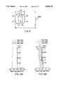
- FIG. 1 shows the outline of the lens system 10a of a first preferred embodiment
- FIGS. 2A-2F provide aberration curves for the lens system 10a illustrated in FIG. 1;
- FIG. 3 shows the outline of the lens system 10b of a second preferred embodiment
- FIGS. 4A-4F provide aberration curves for the lens system 10b illustrated in FIG. 3;
- FIG. 5 shows the outline of the lens system 10c of a third preferred embodiment
- FIGS. 6A-6F provide aberration curves for the lens system 10c illustrated in FIG. 5;
- FIG. 7 shows the outline of the lens system 10d of a fourth preferred embodiment
- FIGS. 8A-8F provide aberration curves for the lens system 10d illustrated in FIG. 7;
- FIG. 9 shows the outline of the lens system 10e of a fifth preferred embodiment
- FIGS. 10A-10F provide aberration curves for the lens system 10e illustrated in FIG. 9;
- FIG. 11 shows the outline of the lens system 10f of a sixth preferred embodiment
- FIGS. 12A-12F provide aberration curves for the lens system 10f illustrated in FIG. 11;
- FIG. 13 shows the outline of the lens system 10g of a seventh preferred embodiment
- FIGS. 14A-14F provide aberration curves for the lens system 10g illustrated in FIG. 13;
- FIG. 15 shows the outline of the lens system 10h of an eighth preferred embodiment
- FIGS. 16A-16F provide aberration curves for the lens system 10h illustrated in FIG. 15;
- FIG. 17 shows the outline of the lens system 10i of a ninth preferred embodiment
- FIGS. 18A-18F provide aberration curves for the lens system 10i illustrated in FIG. 17;
- FIG. 19 is an exploded perspective view of a recyclable single-use camera incorporating the lens system such as 10a-10i;
- FIG. 20 is a front perspective view of the single-use camera 100 shown in FIGS. 1 and 19;
- FIG. 21 is a partial front perspective view of the body of the single-use camera shown in FIGS. 19 and 20;
- FIG. 22 is a partially exploded rear view of the camera shown in FIGS. 19-23;
- FIG. 23 is a partial rear view of the single-use camera of FIG. 22 showing the reloading of a film cassette.
- the following embodiments of the present invention consist of an optical system (also called a lens system) 10a-10i for an objective or taking lens 112 imaging an object on a cylindrical image surface coincident with a photographic film frame F of the film 109 for use in an inexpensive camera such as single lens camera 100.
- the camera 100 includes other known structures or means for advancing the film and a shutter for enabling an exposure of the fill frame F to capture an image of the scene to be photographed.
- the optical system (or the lens system) 10 k comprises two lens components 12 k and 14 k , and a shutter S k , disposed between the two lens components at the aperture stop location.
- the subscript "k" identifies the k th embodiment of the present invention.
- the Photonics Dictionary (1981) defines a shutter as "a mechanical or automatic device used in a camera to control the time in which a light sensitive material is exposed to radiation.” This device is usually an aperture hole and a shutter blade which covers and uncovers the aperture. With this type of shutter, if the shutter is located close to the aperture stop location, the exposure on the film is held uniform.
- the front lens component 12 k of the optical system 10 k is a meniscus lens element E 1k having a concave surface oriented towards the aperture stop (shutter).
- the rear lens component 14 k is a meniscus lens element E 2k . It also has a concave surface oriented towards the aperture stop.
- the front lens component 12 k may or may not have a longer focal length than the rear lens component 14 k .
- Lens system 10 k deviates from a perfectly symmetrical type in that the two lens components 12 k and 14 k are not identical. More specifically, the focal lengths of the two lens components are significantly different from one another and at least one of the two lens components is biaspheric. If only one biaspheric lens component is used, its focal length is typically (but not always) greater than that of the other lens component.
- the aperture stop AS k is located between the two lens elements or on one of the internal lens surfaces.
- the first embodiment is illustrated in FIG. 1. Its specific parameters are provided in Table 1.
- the focal length of optical system 10a is 21.63 mm, the F-number is 8 and the full field of view is 77.4 degrees.
- Both of lens elements E 1a and E 2a of the first embodiment are positive and are made from the same type of plastic.
- the front lens element E 1a is biaspheric and a second lens element E 2a has no aspheric surfaces.
- the front lens element E 1a is biaspheric because both the front surface (surface 1) and the rear surface of the lens element E 1a are aspheric.
- aspheric surfaces with about 290 waves and 114 waves departure from the best fit sphere are used on the first and the second surfaces, respectively, of the biaspheric lens element to control the image quality.
- the use of the aspheric surface and the particular bendings of the lens components (or lens elements) provides the F/8 lens system with the performance equivalent to that of a much slower two element lens system.
- the thickness T of the lens elements be 1 ⁇ T ⁇ 3 mm.
- the lens elements E 1a and E 2a have the thickness of 2.13 mm and 1.78 mm respectively.
- the focal length f 1a of the first lens component 12a is 70.42 mm and the focal length f 2a of the second lens component 14a is 24.47 mm.
- the ratio of f 1a /f 2a 2.88.
- the image surface of the lens system 10a is cylindrical with a sag in the long dimension of the image.
- the cylindrical radius of curvature was in the range of
- this cylindrical radius of curvature is -90 min.
- the aperture stop ASa is located in the airspaced formed between the first lens element E 1a and the second lens element E 2a .
- the ratio of the total length TL of the lens system (measuring from the front-most surface's vertex to the image plane) to the effective focal length (EFL) of the lens system is 1.21.
- FIGS. 2A-2F The aberration curves illustrating the performance of the optical system of the first preferred embodiment are provided in FIGS. 2A-2F.
- FIG. 2A illustrates longitudinal spherical aberration.
- the vertical axis depicts relative aperture.
- the horizontal axis depicts the focus position.
- the primary wavelength is 546.1 nm.
- FIG. 2B illustrates astigmatism in the lens system.
- the vertical axis is the half field angle in degrees.
- the horizontal axis is focus position.
- the "zero focus" on the horizontal axis of the longitudinal spherical aberration (LSA) and astigmatism plots (FIGS. 2A and 2B) is shown referenced to the paraxial focus at 546.1 nm. Since the image is cylindrically curved, we choose to reference the vertical axis of the astigmatism plot to an average curvature of the image format. For simplicity, we choose the best fit radius to the corner of the image format for our reference. The best fit radius is the radius that intersects the cylinder image format in the center and at the corner. This best fit radius is found by multiplying the cylinder film radius by a factor which is dependent on the shape of the image format (i.e. the ratio of the two dimensions of the format).
- the shape of the image format (16.7 ⁇ 30 mm) gives us a multiplying factor of 1.3099 for the best fit radius to the corner of the format.
- a best fit corner radius 16.7 ⁇ 30 mm
- the multiplying factor for the best fit corner radius to a cylindrical image format may be calculated using the following procedure.
- FIG. 2C depicts ray intercept curves for the first embodiment at several relative field positions (axis, 0.5, 0.7, and full field).
- the vertical axis depicts ray aberrations in millimeters.
- the horizontal axis is relative pupil coordinate, the edges being ⁇ full pupil (i.e. ⁇ 1.0 pupil).
- FIG. 2D depicts the lateral color measured in millimeters (440 nm to 650 nm) across the field.
- FIG. 2E depicts the distortion at the primary wavelength (546.1 nm) across the field.
- the distortion definition used here is:
- FIG. 2F depicts heterochromatic through frequency MTF at three field points: axis, 0.7 relative field, and full field. Wavelengths used were 650 nm, 546.1 nm, and 440 nm with respective chromatic weights of 35, 50, and 15.
- the second preferred embodiment is very similar to the first. It is illustrated in FIG. 3.
- the optical system 10b of the second embodiment is constructed from two lens components 12b and 14b and an optical shutter Sb, which is located between those lens components at the location of the aperture stop ASb.
- the front lens component 12b is a meniscus plastic lens element E 1b .
- the rear lens component 14b is a meniscus plastic lens element E 2b .
- the front lens element E 1b is biaspheric and a second lens element E 2b has no aspheric surfaces.
- the front lens component 12b has a longer focal length than the rear lens component 14b.
- the focal length of optical system 10b is 21.63 mm
- the F-number is 8
- the full field of view is 76.8 degrees.
- Both of lens components 12b and 14b are made from the same type of plastic.
- the ratio of the total length TL of the lens system (measuring from the front-most surface's vertex to the image plane) to the effective focal length (EFL) of the lens system is 1.21.
- the lens components 12b and 14b have the thickness of 2.21 mm and 1.81 mm respectively.
- the focal length f 1b of the first lens component 12b is 79.55 mm and the focal length f 2b of the second lens component 14b is 23.36 mm.
- the ratio of f 1b /f 2b 3.41.
- the image surface of the lens system 10b is cylindrical with a sag in the long dimension of the image. In this embodiment, this cylindrical radius of curvature is -120 mm.
- Aspheric surfaces with about 312 waves and 120 waves departure from the best fit sphere, are used on the first and the second surfaces, respectively, of the biaspheric lens element to control the image quality.
- FIG. 4A-4F The aberration curves illustrating the performance of the optical system of the second embodiment are provided in FIG. 4A-4F.
- FIG. 4A illustrates longitudinal spherical aberration.
- the vertical axis depicts relative aperture.
- the horizontal axis depicts the focus position.
- the primary wavelength is 546.1 nm.
- FIG. 4B illustrates astigmatism in the lens system.
- the vertical axis is the half field angle in degrees.
- the horizontal axis is focus position.
- the "zero focus" on the horizontal axis of the longitudinal spherical aberration (LSA) and astigmatism plots (FIGS. 4A and 4B) is shown referenced to the paraxial focus at 546.1 nm. Since the image is cylindrically curved, we choose to reference the vertical axis of the astigmatism plot to an average curvature of the image format. For simplicity, we again choose the best fit radius to the corner of the image format for our reference. For this second embodiment, the shape of the image format (16.7 ⁇ 30 mm) gives us a multiplying factor of 1.3099 for the best fit radius to the corner of the format. Using this with the -120 mm cylinder radius, we get a best fit corner radius of -157.19 mm. All of the aberrations shown which are dependent on field are referenced to this best fit radius.
- FIG. 4C depicts ray intercept curves for the second embodiment at several relative field positions (i.e. axis, 0.5, 0.7, and full field).
- the vertical axis depicts ray aberrations in millimeters.
- the horizontal axis is relative pupil coordinate, the edges being ⁇ full pupil (i.e. ⁇ 1.0 pupil).
- FIG. 4D depicts the lateral color (440 nm to 650 nm) across the field.
- FIG. 4E depicts the distortion at the primary wavelength (546.1 nm) across the field.
- FIG. 4F depicts heterochromatic through frequency MTF at three field points: axis, 0.7 relative field, and full field. Wavelengths used were 650 nm, 546.1 nm, and 440 nm with respective chromatic weights of 35, 50, and 15.
- the third preferred embodiment is very similar to the first and the second preferred embodiments. It is illustrated in FIG. 5.
- the front lens component 12c of the optical system 10c is a meniscus plastic lens element E 1c .
- the rear lens component 14c is a meniscus plastic lens element E 2c .
- the front lens component 12c is biaspheric.
- the aperture stop ASc is located in the airspaced formed between the first lens element E 1c and the second lens element E 2c .
- the focal length of optical system 10c is 24 mm
- the F-number is 8
- the full field of view is 71.8 degrees.
- Both of lens elements E 1c and E 2c of the third embodiment are positive and are made from the same type of plastic.
- the lens components 12c and 14c have the thickness of 1.92 mm and 1.70 mm respectively.
- the focal length f 1b of the first lens component 12c is 62.9 mm and the focal length f 2b of the second lens component 14c is 29.91 mm.
- the ratio of f 1c /f 2c 2.10.
- the image surface of the lens system 10c is cylindrical with a sag in the long dimension of the image.
- this cylindrical radius of curvature is -90 mm.
- Aspheric surfaces with about 209 waves and 94 waves departure from the best fit sphere, are used on the first and the second surfaces, respectively, of the biaspheric lens element to control the image quality.
- the ratio of the total length TL of the lens system (measuring from the front-most surface's vertex to the image plane) to the effective focal length (EFL) of the lens system is 1.17.
- FIGS. 6A-6F The aberration curves illustrating the performance of the optical system of the third preferred embodiment are provided in FIGS. 6A-6F.
- FIG. 6A illustrates longitudinal spherical aberration.
- the vertical axis depicts relative aperture.
- the horizontal axis depicts the focus position.
- the primary wavelength is 546.1 nm.
- FIG. 6B illustrates astigmatism in the lens system.
- the vertical axis is the half field angle in degrees.
- the horizontal axis is focus position.
- the "zero focus" on the horizontal axis of the longitudinal spherical aberration (LSA) and astigmatism plots (FIGS. 6A and 6B) is shown referenced to the paraxial focus at 546.1 nm. Since the image is cylindrically curved, we choose to reference the vertical axis of the astigmatism plot to an average curvature of the image format. For simplicity, we again choose the best fit radius to the corner of the image format for our reference. For this third embodiment, the shape of the image format (16.7 ⁇ 30 mm) gives us a multiplying factor of 1.3099 for the best fit radius to the corner of the format. Using this with the -90 mm cylinder radius, we get a best fit corner radius of -117.89 mm. All of the aberrations shown which are dependent on field are referenced to this best fit radius.
- FIG. 6C depicts ray intercept curves for the third embodiment at several relative field positions (i.e. axis, 0.5, 0.7, and full field).
- the vertical axis depicts ray aberrations in millimeters.
- the horizontal axis is relative pupil coordinate, the edges being ⁇ full pupil (i.e. ⁇ 1.0 pupil).
- FIG. 6D depicts the lateral color (440 nm to 650 nm) across the field.
- FIG. 6E depicts the distortion at the primary wavelength (546.1 nm) across the field.
- FIG. 6F depicts heterochromatic through frequency MTF at three field points: axis, 0.7 relative field, and full field. Wavelengths used were 650 nm, 546.1 nm, and 440 nm with respective chromatic weights of 35, 50, and 15.
- the fourth preferred embodiment is illustrated in FIG. 7.
- the optical system 10d of the fourth embodiment is constructed from two lens components 12d and 14d.
- the front lens component 12d is a meniscus plastic lens element E 1d .
- the rear lens component 14d is a meniscus plastic lens element E 2d .
- the front lens element E 1d is biaspheric and a second lens element E 2d has no aspheric surfaces.
- the front lens component 12d has a longer focal length than the rear lens component 14d.
- the focal length of optical system 10d is 24 mm
- the F-number is 8
- the full field of view is 71 degrees.
- Both of lens components 12d and 14d are made from the same type of plastic.
- the lens components 12d and 14d have the thickness of 1.97 mm and 1.72 mm respectively.
- the focal length f 1d of the first lens component 12d is 64.82 mm and the focal length f 2d of the second lens component 14d is 29.25 mm.
- the ratio of f 1d /f 2d 2.22.
- the image surface of the lens system 10d is cylindrical with a sag in the long dimension of the image. In this embodiment, this cylindrical radius of curvature is -120 mm.
- Aspheric surfaces with about 221 waves and 100 waves departure from the best fit sphere, are used on the first and the second surfaces, respectively, of the biaspheric lens element to control the image quality.
- the ratio of the total length TL of the lens system (measuring from the front-most surface's vertex to the image plane) to the effective focal length (EFL) of the lens system is 1.17.
- FIG. 8A-8F The aberration curves illustrating the performance of the optical system of the fourth embodiment are provided in FIG. 8A-8F.
- FIG. 8A illustrates longitudinal spherical aberration.
- the vertical axis depicts relative aperture.
- the horizontal axis depicts the focus position.
- the primary wavelength is 546.1 nm.
- FIG. 8B illustrates astigmatism in the lens system.
- the vertical axis is the half field angle in degrees.
- the horizontal axis is focus position.
- the "zero focus" on the horizontal axis of the longitudinal spherical aberration (LSA) and astigmatism plots (FIGS. 8A and 8B) is shown referenced to the paraxial focus at 546.1 nm. Since the image is cylindrically curved, we choose to reference the vertical axis of the astigmatism plot to an average curvature of the image format. For simplicity, we again choose the best fit radius to the corner of the image format for our reference. For this fourth embodiment, the shape of the image format (16.7 ⁇ 30 mm) gives us a multiplying factor of 1.3099 for the best fit radius to the corner of the format. Using this with the -120 mm cylinder radius, we get a best fit corner radius of -157.19 mm. All of the aberrations shown which are dependent on field are referenced to this best fit radius.
- FIG. 8C depicts ray intercept curves for the fourth embodiment at several relative field positions (i.e. axis, 0.5, 0.7, and full field).
- the vertical axis depicts ray aberrations in millimeters.
- the horizontal axis is relative pupil coordinate, the edges being ⁇ full pupil (i.e. ⁇ 1.0 pupil).
- FIG. 8D depicts the lateral color (440 nm to 650 nm) across the field.
- FIG. 8E depicts the distortion at the primary wavelength (546.1 nm) across the field.
- FIG. 8F depicts heterochromatic through frequency MTF at three field points: axis, 0.7 relative field, and full field. Wavelengths used were 650 nm, 546.1 nm, and 440 nm to with respective chromatic weights of 35, 50, and 15.
- the fifth preferred embodiment 10e is illustrated in FIG. 9.
- the front lens component 12e of the optical system 10e is a meniscus plastic lens element E 1e .
- the rear lens component 14e is a meniscus plastic lens element E 2e .
- the two lens components are manufactured from different plastics.
- the front lens component 12e is biaspheric.
- the aperture stop ASe is located in the airspaced formed between the first lens element E 1e and the second lens element E 2e .
- the focal length of optical system 10e is 25 mm
- the F-number is 11
- the full field of view is 74.94 degrees.
- Both of lens elements E 1e and E 2e of the fifth embodiment are positive.
- the lens components 12e and 14e have the thickness of 2.096 mm and 1.633 mm respectively.
- the focal length f 1e of the first lens component 12e is 39.00 mm and the focal length f 2e of the second lens component 14e is 48.28 mm.
- the ratio of f 1e /f 2e 0.81. Therefore, the biaspheric lens component is the more powerful lens component. This is different from the proceeding embodiments.
- the image surface of the lens system 10e is cylindrical with a sag in the long dimension of the image.
- this cylindrical radius of curvature is -120 mm.
- Aspheric surfaces with about 139 waves and 56 waves departure from the best fit sphere, are used on the first and the second surfaces, respectively, of the biaspheric lens element to control the image quality.
- the ratio of the total length TL of the lens system (measuring from the front-most surface's vertex to the image plane) to the effective focal length (EFL) of the lens system is 1.10.
- FIGS. 10A-10F The aberration curves illustrating the performance of the optical system of the fifth preferred embodiment are provided in FIGS. 10A-10F.
- FIG. 10A illustrates longitudinal spherical aberration.
- the vertical axis depicts relative aperture.
- the horizontal axis depicts the focus position.
- the primary wavelength is 546.1 nm.
- FIG. 10B illustrates astigmatism in the lens system.
- the vertical axis is the half field angle in degrees.
- the horizontal axis is focus position.
- the "zero focus" on the horizontal axis of the longitudinal spherical aberration (LSA) and astigmatism plots (FIGS. 10A and 10B) is shown referenced to the paraxial focus at 546.1 nm. Since the image is cylindrically curved, we choose to reference the vertical axis of the astigmatism plot to an average curvature of the image format. For simplicity, we choose the best fit radius to the corner of the image format for our reference. For this fifth embodiment, the shape of the image format (13.3 ⁇ 36.4 mm) gives us a multiplying factor of 1.1335 for the best fit radius to the corner of the format. Using this with the -120 mm cylinder radius, we get a best fit corner radius of -136.02 mm. All of the aberrations shown which are dependent on field are referenced to this best fit radius.
- FIG. 10C depicts ray intercept curves for the fifth embodiment at several relative field positions (i.e. axis, 0.5, 0.7, and full field).
- the vertical axis depicts ray aberrations in millimeters.
- the horizontal axis is relative pupil coordinate, the edges being ⁇ full pupil (i.e. ⁇ 1.0 pupil).
- FIG. 10D depicts the lateral color (440 nm to 650 nm) across the field.
- FIG. 10E depicts the distortion at the primary wavelength (546.1 nm) across the field.
- FIG. 10F depicts heterochromatic through frequency MTF at three field points: axis, 0.7 relative field, and full field. Wavelengths used were 650 nm, 546.1 nm, and 440 nm with respective chromatic weights of 35, 50, and 15.
- the sixth preferred embodiment is illustrated in FIG. 11.
- the front lens component 12f of the optical system 10f is a meniscus plastic lens element E 1f .
- the rear lens component 14f is a meniscus plastic lens element E 2f .
- Both front lens component 12f and the rear component 14f are biaspheric.
- the aperture stop ASf is located in the airspaced formed between the first lens element E 1f and the second lens element E 2f .
- the focal length of optical system 10f is 24 mm
- the F-number is 8
- the full field of view is 70.1 degrees.
- Both of lens elements E 1f and E 2f of the sixth embodiment are positive and are manufactured from the different plastics.
- the lens components 12f and 14f have the thickness of 2.015 mm and 2.436 mm respectively.
- the focal length f 1f of the first lens component 12f is 20.54 mm and the focal length f 2f of the second lens component 14f is 10, 107 mm.
- the ratio of f 1f /f 2f 0.002.
- the image surface of the lens system 10f is cylindrical with a sag in the long dimension of the image.
- this cylindrical radius of curvature is -120 mm.
- Aspheric surfaces with about 27 waves and 6 waves departure from the best fit spheres are used on the first and the second surfaces, respectively, of the front biaspheric lens element to control the image quality.
- Aspheric surfaces with about 75 waves and 139 waves departure from the best fit spheres are used on the first and second surfaces, respectively, of the second biaspheric lens element to control the image quality.
- the ratio of the total length TL of the lens system (measuring from the front-most surface's vertex to the image plane) to the effective focal length (EFL) of the lens system is 1.07.
- FIGS. 12A-12F The aberration curves illustrating the performance of the optical system of the sixth preferred embodiment are provided in FIGS. 12A-12F.
- FIG. 12A illustrates longitudinal spherical aberration.
- the vertical axis depicts relative aperture.
- the horizontal axis depicts the focus position.
- the primary wavelength is 546.1 nm.
- FIG. 12B illustrates astigmatism in the lens system.
- the vertical axis is the half field angle in degrees.
- the horizontal axis is focus position.
- the "zero focus" on the horizontal axis of the longitudinal spherical aberration (LSA) and astigmatism plots (FIGS. 12A and 12B) is shown referenced to the paraxial focus at 546.1 nm. Since the image is cylindrically curved, we choose to reference the vertical axis of the astigmatism plot to an average curvature of the image format. For simplicity, we choose the best fit radius to the corner of the image format for our reference. For this sixth embodiment, the shape of the image format (16.7 ⁇ 30 mm) gives us a multiplying factor of 1.3099 for the best fit radius to the corner of the format. Using this with the -120 mm cylinder radius, we get a best fit corner radius of -157.19 mm. All of the aberrations shown which are dependent on field are referenced to this best fit radius.
- FIG. 12C depicts ray intercept curves for the sixth embodiment at several relative field positions (i.e. axis, 0.5, 0.7, and full field).
- the vertical axis depicts ray aberrations in millimeters.
- the horizontal axis is relative pupil coordinate, the edges being ⁇ full pupil (i.e. ⁇ 1.0 pupil).
- FIG. 12D depicts the lateral color (440 nm to 650 nm) across the field.
- FIG. 12E depicts the distortion at the primary wavelength (546.1 nm) across the field.
- FIG. 12F depicts heterochromatic through frequency MTF at three field points: axis, 0.7 relative field, and full field. Wavelengths used were 650 nm, 546.1 nm, and 440 nm with respective chromatic weights of 35, 50, and 15.
- the seventh through the ninth embodiments are most preferred, because the biaspheric lens component of these embodiments has a greatly reduced sensitivity to the aspheric surface decenter.
- the method for reducing lens system sensitivity to an aspheric surface decenter is described in detail further in the specification.
- the seventh preferred embodiment is illustrated in FIG. 13.
- the front lens component 12g of the optical system 10g is a meniscus plastic lens element E 1g .
- the rear lens component 14g is a meniscus plastic lens element E 2g .
- the front lens component 12g is biaspheric.
- the aperture stop ASg is located in the airspaced formed between the first lens element E 1g and the second lens element E 2g .
- the focal length of optical system 10g is 24 mm
- the F-number is 8
- the full field of view is 71.7 degrees.
- Both of lens elements E 1g and E 2g of the seventh embodiment are positive and are made from the same type of plastic.
- the lens components 12g and 14g have the thickness of 2.85 mm and 2.0 mm respectively.
- the focal length f 1g of the first lens component 12g is 81.01 mm and the focal length f 2g of the second lens component 14g is 26.84 mm.
- the ratio of f 1g /f 2g 3.02.
- the image surface of the lens system 10g is cylindrical with a sag in the long dimension of the image.
- this cylindrical radius of curvature is -90 mm.
- Aspheric surfaces with about 143 waves and 48 waves departure from the best fit sphere, are used on the first and the second surfaces, respectively, of the biaspheric lens element to control the image quality.
- the ratio of the total length TL of the lens system (measuring from the front-most surface's vertex to the image plane) to the effective focal length (EFL) of the lens system is 1.22.
- FIGS. 14A-14F The aberration curves illustrating the performance of the optical system of the seventh preferred embodiment are provided in FIGS. 14A-14F.
- FIG. 14A illustrates longitudinal spherical aberration.
- the vertical axis depicts relative aperture.
- the horizontal axis depicts the focus position.
- the primary wavelength is 546.1 nm.
- FIG. 14B illustrates astigmatism in the lens system.
- the vertical axis is the half field angle in degrees.
- the horizontal axis is focus position.
- the "zero focus" on the horizontal axis of the longitudinal spherical aberration (LSA) and astigmatism plots (FIGS. 14A and 14B) is shown referenced to the paraxial focus at 546.1 nm. Since the image is cylindrically curved, we choose to reference the vertical axis of the astigmatism plot to an average curvature of the image format. For simplicity, we choose the best fit radius to the corner of the image format for our reference. For this seventh embodiment, the shape of the image format (16.7 ⁇ 30 mm) gives us a multiplying factor of 1.3099 for the best fit radius to the corner of the format. Using this with the -90 mm cylinder radius, we get a best fit corner radius of -117.89 mm. All of the aberrations shown which are dependent on field are referenced to this best fit radius.
- FIG. 14C depicts ray intercept curves for the seventh embodiment at several relative field positions (i.e. axis, 0.5, 0.7, and full field).
- the vertical axis depicts ray aberrations in millimeters.
- the horizontal axis is relative pupil coordinate, the edges being ⁇ full pupil (i.e. ⁇ 1.0 pupil).
- FIG. 14D depicts the lateral color (440 nm to 650 nm) across the field.
- FIG. 14E depicts the distortion at the primary wavelength (546.1 nm) across the field.
- FIG. 14F depicts heterochromatic through frequency MTF at three field points: axis, 0.7 relative field, and full field. Wavelengths used were 650 nm, 546.1 nm, and 440 nm with respective chromatic weights of 35, 50, and 15.
- the eighth preferred embodiment is illustrated in FIG. 15.
- the optical system 10h of the eighth embodiment is constructed from two lens components 12h and 14h.
- the front lens component 12h is a meniscus plastic lens element E 1h .
- the rear lens component 14h is a meniscus plastic lens element E 2h .
- a different plastic material is used for each lens component.
- This embodiment is different from some of the above described embodiments. It contains not two, but three aspheric surfaces, and it is the second and not the first lens component that is biaspheric.
- the front lens element E 1h contains a single aspheric surface which is located on a front-most (i.e., object side) surface of the lens element.
- the second lens element E 2h is biaspheric.
- the front lens component 12h has a shorter focal length than the rear lens component 14h.
- the focal length of optical system 10h is 24 mm
- the F-number is 8
- the full field of view is 70.3 degrees.
- Lens components 12h and 14h are made from different types of plastic.
- the ratio of the total length TL of the lens system (measuring from the front-most surface's vertex to the image plane) to the effective focal length (EFL) of the lens system is 1.08.
- the lens components 12h and 14h have the thickness of 2.85 mm and 2.5 mm respectively.
- the focal length f 1h of the first lens component 12h is 22.28 mm and the focal length f 2h of the second lens component 14h is 220.14 mm.
- the ratio of f 1h /f 2h 0.10.
- An aspheric surface with about 18 waves departure from the best fit sphere is used on the front surface of lens element E 1h .
- Aspheric surfaces with about 52 waves and 123 waves departure from the best fit sphere, are used on the first and the second surfaces, respectively, of the biaspheric lens element E 2h to control the image quality.
- FIGS. 16A-16F The aberration curves illustrating the performance of the optical system of the eighth embodiment are provided in FIGS. 16A-16F.
- FIG. 16A illustrates longitudinal spherical aberration.
- the vertical axis depicts relative aperture.
- the horizontal axis depicts the focus position.
- the primary wavelength is 546.1 nm.
- FIG. 16B illustrates astigmatism in the lens system.
- the vertical axis is the half field angle in degrees.
- the horizontal axis is focus position.
- the "zero focus" on the horizontal axis of the longitudinal spherical aberration (LSA) and astigmatism plots (FIGS. 16A and 16B) is shown referenced to the paraxial focus at 546.1 nm. Since the image is cylindrically curved, we choose to reference the vertical axis of the astigmatism plot to an average curvature of the image format. For simplicity, we choose the best fit radius to the corner of the image format for our reference. For this eighth embodiment, the shape of the image format (16.7 ⁇ 30 mm) gives us a multiplying factor of 1.3099 for the best fit radius to the corner of the format. Using this with the -120 mm cylinder radius, we get a best fit corner radius of -157.19 mm. All of the aberrations shown which are dependent on field are referenced to this best fit radius.
- FIG. 16C depicts ray intercept curves for the eighth embodiment at several relative field positions (i.e. axis, 0.5, 0.7, and full field).
- the vertical axis depicts ray aberrations in millimeters.
- the horizontal axis is relative pupil coordinate, the edges being ⁇ full pupil (i.e. ⁇ 1.0 pupil).
- FIG. 16D depicts the lateral color (440 nm to 650 nm) across the field.
- FIG. 16E depicts the distortion at the primary wavelength (546.1 nm) across the field.
- FIG. 16F depicts heterochromatic through frequency MTF at three field points: axis, 0.7 relative field, and full field. Wavelengths used were 650 nm, 546.1 nm, and 440 nm with respective chromatic weights of 35, 50, and 15.
- the ninth preferred embodiment is illustrated in FIG. 17.
- the front lens component 12i of the optical system 10i is a positive power meniscus lens element E 1i which is a glass lens element.
- the rear lens component 14i is a meniscus plastic lens element E 2i .
- the rear lens component 12i is biaspheric and has negative optical power.
- the aperture stop ASi is located in the airspaced formed between the first lens element E 1i and the second lens element E 2i .
- the focal length of optical system 10i is 28 mm
- the F-number is 8
- the full field of view is 62.92 degrees.
- the lens system of the ninth embodiment is athermalized. That is, that a 30° C. temperature change produces only essentially no image shift (i.e. it produces a minimum -0.02 mm image distance shift).
- a minimum image shift is defined as image shift of less than
- the lens components 12i and 14i have the thickness of 3.33 mm and 2.92 mm respectively.
- the image surface of the lens system 10i is cylindrical with a sag in the long dimension of the image.
- this cylindrical radius of curvature is -120 mm.
- Aspheric surfaces with about 98 waves and 209 waves departure from the best fit sphere, are used on the first and the second surfaces, respectively, of the biaspheric lens element to control the image quality.
- the ratio of the total length TL of the lens system (measuring from the front-most surface's vertex to the image plane) to the effective focal length (EFL) of the lens system is 1.05.
- FIGS. 18A-18F The aberration curves illustrating the performance of the optical system of the ninth preferred embodiment are provided in FIGS. 18A-18F.
- FIG. 18A illustrates longitudinal spherical aberration.
- the vertical axis depicts relative aperture.
- the horizontal axis depicts the focus position.
- the primary wavelength is 546.1 nm.
- FIG. 18B illustrates astigmatism in the lens system.
- the vertical axis is the half field angle in degrees.
- the horizontal axis is focus position.
- the "zero focus" on the horizontal axis of the longitudinal spherical aberration (LSA) and astigmatism plots (FIGS. 18A and 18B) is shown referenced to the paraxial focus at 546.1 nm. Since the image is cylindrically curved, we choose to reference the vertical axis of the astigmatism plot to an average curvature of the image format. For simplicity, we choose the best fit radius to the corner of the image format for our reference. For this ninth embodiment, the shape of the image format (16.7 ⁇ 30 mm) gives us a multiplying factor of 1.3099 for the best fit radius to the corner of the format. Using this with the -120 mm cylinder radius, we get a best fit corner radius of -157.19 mm. All of the aberrations shown which are dependent on field are referenced to this best fit radius.
- FIG. 18C depicts ray intercept curves for the ninth embodiment at several relative field positions (i.e. axis, 0.5, 0.7, and 1.0).
- the vertical axis depicts ray aberrations in millimeters.
- the horizontal axis is relative pupil coordinate, the edges being ⁇ full pupil (i.e. ⁇ 1.0 pupil).
- FIG. 18D depicts the lateral color (440 nm to 650 nm) across the field.
- FIG. 18E depicts the distortion at the primary wavelength (546.1 nm) across the field.
- FIG. 18F depicts heterochromatic through frequency MTF at three field points: axis, 0.7 relative field, and full field. Wavelengths used were 650 nm, 546.1 nm, and 440 nm with respective chromatic weights of 35, 50, and 15.
- LSA was calculated for each lens system at a wavelength of 546.1 nm.
- Numbers shown below are the maximums for 440 nm to 650 nm.
- the maximum laterial color does not always occur at the edge of the field.
- a lens system is designed with field angles covering only half of the image because of lens symmetry (from axis to one edge of the image).
- lens symmetry from axis to one edge of the image.
- the film radius described for the preferred embodiments is the actual cylinder radius, not the best fit corner radius used to do the design.
- a lens system with a biaspheric lens element is difficult to manufacture due to the sensitivity of the lens system to the displacement of one of the aspheric surfaces of such a lens element relative to the other surface.
- a decenter ⁇ of 0.025 mm which is a reasonable molding tolerance, causes a noticeable loss in MTF (Modulation Transfer Function) in the image as you move away from the axis. Molding to tighter tolerances increases the cost of the element.
- a desensitizing procedure was used to design the seventh, eighth, and ninth embodiments.
- a decenter of 0.025 mm was inserted during the lens design procedure on the first (i.e. front-most) surface of the biaspheric element. All other surfaces were centered on a common axis (i.e. 0.025 mm from where the first biaspheric surface is decentered to).
- a common axis i.e. 0.025 mm from where the first biaspheric surface is decentered to.
- the 71% field heterochromatic MTF performance along the diagonal went from 65/74 (sagittal/tangential) at 12.5 lines per millimeter to 60/72 (sagittal/tangential) with a ⁇ 0.025 mm decenter and 69/58 (sagittal/tangential) with a-0.025 mm decenter. This is much less MTF image degradation than a typical undesensitized lens would produce.
- the heterochromatic wavelength weights used are 546 nm/50, 440 nm/15, and 650 nm/35. For this analysis, positive (i.e. uphill) field angle rays were traced.
- the 71% field heterochromatic MTF performance went from 70/75 (sagittal/tangential) at 12.5 lines per millimeter to 67/73 (sagittal/tangential) for a+0.025 mm decenter and 72/69 (sagittal/tangential) for a-0.025 mm decenter, again this is much less than the degradation produced by a regularly designed and manufactured lens system with a biaspheric element.
- the biaspheric element is difficult to make. Quality control especially would make it much more expensive to produce.
- lens element is not intended to include such lens elements or components for purposes of the present application. It is also to be understood that other embodiments of the present invention may be scaled up or down.
- Optical systems in accordance with the present invention are particularly well suited for use in cameras which create large aspect ratio images, with the larger dimension of the image area being curved in conformity with the cylindrical image surface. They have an advantage of providing a low F/number, i.e. an F/number below F/11, such as F/8, while maintaining the performance of a much slower optical system (such as a typical F/14 lens system, for example).
- the invention is incorporated into the camera (FIGS. 19-23) of U.S. Pat. No. 5,604,639 which would be modified to include the taking lens 112.
- the shutter blade is located at the aperture stop position--i.e. between the two lens elements of the lens 10 k .
- a taking lens 112 or a lens system such as 10 k can be contained within the assemblage of a camera, such as a recyclable single-use camera 100 having three major structural components: a main body or frame 102, a front cover 120 which is attached to the front of the body, and a rear cover 130 which is attached to the rear of the body.
- the body 102 includes a pair of formed chambers 104, 106 for retaining a film cassette 108 and a take-up roll, such as spool 110, respectively.
- the pair of chambers 104, 106 are oppositely disposed relative to an exposure gate 107, FIG. 23.
- the body 102 additionally supports the following camera parts which are attached to the body prior to the attachment of the covers 120, 130: the taking lens 112 or the optical system such as lens 10 k which is attached to the front of the body 102 by means of a retainer 114 and a support plate 116 sandwiching the lens therebetween, wherein the support plate has a contact switch 117; and a plastic viewfinder 118.
- a shutter mechanism 119 consisting of a keeper plate 122 having a depressible shutter release portion for tripping a shutter blade 124, biased by a spring 123 via a high-energy lever 126 which is also biased by helical spring 127; a film advancing and metering mechanism consisting of a thumbwheel 128 which engages the spool (not shown) of the loaded film cassette 108, a sprocket 132 for engaging film perforations having a spring biased portion extending into a rotatable cam 134 which engages a metering lever 136 which is biased by means of a spring 138, the cam having an extending portion 138 for contacting a frame counter 140; a light baffle 142 which is mounted into the rear of the body 102 and into the exposure gate 107, FIG.
- the flash illumination assembly 30 having an anamorphic lens 10' and further including a capacitor 146 and circuit board 148 which is powered by a battery 150.
- the illumination assembly 30 is made operable, preferably according to the particular embodiment, by a one touch cantilevered portion of the front cover 120, FIG. 20.
- the front cover 120 and the rear cover 130 are sandwiched together along with the body 102 to form an assembled camera and a label 152 is subsequently attached to the finished camera 100.
- Single-use cameras such as the described camera 100, are designed to be recycled by the manufacturer after a purchaser has completed exposing the loaded film and turned the camera over to a photofinisher for development of the film.
- the photofinisher opens a door 154 on the rear cover 130 and removes the fill cassette 108.
- the opening of the door 154 breaks the rear cover 130, but without damaging or exposing the camera parts which are attached to the body 102.
- a second breakaway door 156 can also be provided on the rear cover 130 to be opened by the photofinisher to remove the flash battery 150, if desired. See FIG. 22.
- the camera 100 is then turned over to the manufacturer for recycling as will now be described with reference to the FIGS. 19-23.
- the front cover 120 and rear cover 130 are each broken away from the body 102, each having releasable hooks (not shown) or other attachment means for allowing removal of the covers from the body.
- the covers made from a recyclable plastic such as polystyrene, can be sent to be pulverized.
- an evaluation can be made as to each of the parts supported by the body 102; i.e.: the viewfinder s 118, shutter mechanism 119, flash illumination assembly 30, the optical system 10 k , etc., or the lens elements of the optical system. Those parts deemed worn are removed from the body 102 and replaced.
- Those remaining single-use parts such as the optical system 10 k or the lens cell containing these lens elements, such as the front lens element 12 k , the camera flash assembly 30, shutter mechanism 119, etc., which can be reused remain supported by the body 102, for reassembly of a camera 100.
- a new front cover 120 is then fitted to the front face of the body 102 and an unexposed roll of film 109 contained within a fresh cassette 108 is loaded into the film cartridge chamber 104. A leading portion of the film 109 contained with the cassette 108 is then engaged with the take-up spool 110, housed within the body chamber 106, as is conventionally known. A new rear cover 130 is then snapped or otherwise attached onto the rear of the camera body 102 and/or to the from cover 120. It should be readily apparent that the covers 120, 130 and body 102 may utilize a number of means for attaching the structural parts together; for example, hook and/or press fitting members may be used, or the parts can be ultrasonically welded together.
- the film 109 is then pre-wound onto the take-up spool 110 which is supported for rotation in chamber 106 so that the film is wound back into the cassette 108 as the film is being exposed.
- the recycled single-use camera 100 utilizing previously used single-use camera parts, such as the flash illumination assembly 30, and the particularly described lens system 10 k is now fully assembled and ready for consumer use.
- the invention provides for making a single-use camera from previously used single-use camera parts utilizing the above-mentioned optical system 10 k as a taking lens 112 for such camera.
Abstract
Description
______________________________________
                       Amount of
Embodiment
          F-           Spherical
                                Number of
Number    Number       Aberration
                                Aspheres
______________________________________
7th       8.0          .111 mm  2
8th       8.0          .075 mm  3
9th       8.0          .024 mm  2
______________________________________
ASTIGMATISM
AMOUNT OF ASTIGMATISM*
        7th           8th       9th
RELF    Embodiment    Embodiment
                                Embodiment
______________________________________
 0      0             0         0
        .00 mm        .01 mm    .03 mm
        .01 mm        .04 mm    .06 mm
        .08 mm        .08 mm    .06 mm
        .23 mm        .12 mm    .07 mm
        .40 mm        .16 mm    .15 mm
        .50 mm        .20 mm    .21 mm
        .51 mm        .24 mm    .14 mm
         .51 mm**      .28 mm** .06 mm
        .51 mm        .14 mm    .15 mm
1.0     .12 mm        .15 mm     .22 mm**
______________________________________
 *The amount of astigmatism is measured for each lens at a wavelength of
 546.1 nm. These embodiments have an Fnumber at F/8. RELF means relative
 field.
 **Indicates the worst astigmatism point in each lens.
______________________________________
Embodiment
          Amount of
Number    Lateral Color
______________________________________
7th       .0079 mm    (maximum is at .6 relative field)
8th       .0075 mm    (maximum is at .9 relative field)
9th       .0121 mm    (maximum is at .7 relative field)
______________________________________
MTF ANALYSIS
Embodiment
        F/               .7 Rel.
                                1.0 Rel.
                                       Full
Number  Number   Axis    Field  Field  Field Angle
______________________________________
MTF AT 5 LINES PER MILLIMETER*
(TANGENTIAL/SAGITTAL)
7th     8.0      94.9    92.6/90.1
                                89.1/91.6
                                       ±35.8 DEG.
8th     8.0      94.6    92.0/90.6
                                82.9/92.6
                                       ±35.2 DEG.
9th     8.0      95.1    92.5/93.1
                                89.7/93.7
                                       ±31.5 DEG.
MTF AT 20 LINES PER MILLIMETER*
(TANGENTIAL/SAGITTAL)
7th     8.0      67.5    56.3/45.8
                                50.1/56.2
                                       ±35.8 DEG.
8th     8.0      64.8    58.5/52.4
                                41.7/59.4
                                       ±35.2 DEG.
9th     8.0      68.9    57.2/61.9
                                49.0/64.4
                                       ±31.5 DEG.
______________________________________
 *Heterochromatic MTF at best focus, wavelengths/weights used are 546.1
 nm/50, 440 nm/15, and 650 nm/35.
              TABLE 1
______________________________________
      Clear    Axial           Thick-
                                     Index
                                          V-Number
Surface
      Aperture Beam   Radius   ness  N.sub.d
                                          V.sub.d
______________________________________
1     7.05     2.70   ASPHERE  2.130 1.492
                                          57.4
2     4.70     2.34   ASPHERE  1.700
      2.30     2.30   DIAPHRAGM
                               1.570
3     4.70     2.25   -6.72200 1.780 1.492
                                          57.4
4     6.35     2.41   -4.69690
______________________________________
LENS LENGTH 7.180
Where the radius of curvature for a surface, the axial thickness and air
separations are measured in millimeters.
Aspheric Equation:
 ##STR1##
Surf. 1
      C = 0.1794784
                 D = 0.5737500E-04
                               F = 0.1060700E-06
      k = 1.3880800
                 E = 0.8680000E-05
                               G = 0.6135300E-08
VERTEX RADIUS (1/C) = 5.5717
Surf. 2
      C = 0.1725209
                 D = 0.2122000E-03
                               F = -0.1845100E-04
      k = 4.3530000
                 E = 0.1111500E-03
                               G = 0.3731300E-06
VERTEX RADIUS (1/C) = 5.7964
______________________________________
Notes:
______________________________________
1.    EF = 21.63          F/No. = F/ 8.00
      Semi-Field = 38.69 Deg.
                          BF = 19.09
      Semi-Diag. = 17.17  FF = 16.72
      Format = 16.7 × 30.0
                          Best Focus = -.16
Principal wavelength is 546 nm, achromatism: 440-650 nm.
The plastic material having index N.sub.d and Abbe V-number of
1.492 and 57.4, respectively.
Wavelength
(Microns)    Refractive Index
______________________________________
0.65000000   1.489394
0.54610000   1.493777
0.44000000   1.502120
______________________________________
2.    Image surface is a cylinder with radius -90. Long dimension of
      image format is measured along cylinder radius of curvature.
Image        Angular Max. Aper. With
Height       Field   No. Vignetting
______________________________________
 5.60        14.64   F/ 8.0
11.98        29.28   F/ 8.0
17.17        38.69   F/ 8.0
______________________________________
Pupil          Location Diameter
______________________________________
Entrance        3.92    2.70
Exit           -3.58    2.83
______________________________________
3.    MTF data is at best focus along diagonal of the above image
      format using wavelengths 650, 546.1, and 440 nm, with
      respective weights .35, .5, and .15:
          Percent Field (Sagittal/Tangential)
F/No.
     L/MM    Axis   38%   57%  71%   86%  95%   100%
______________________________________
8.0  7.      92     92/91 89/90
                               87/89 89/86
                                          91/83 90/80
8.0  12.5    92     82/79 76/78
                               72/77 75/72
                                          79/68 78/65
8.0  22.     62     67/57 57/58
                               52/59 57/56
                                          61/50 59/45
______________________________________
              TABLE 2
______________________________________
      Clear    Axial           Thick-
                                     Index
                                          V-Number
Surface
      Aperture Beam   Radius   ness  N.sub.d
                                          V.sub.d
______________________________________
1     7.06     2.70   ASPHERE  2.210 1.492
                                          57.4
2     4.63     2.32   ASPHERE  1.700
      2.28     2.28   DIAPHRAGM
                               1.500
3     4.64     2.24   -6.38860 1.810 1.492
                                          57.4
4     6.23     2.42   -4.49680
______________________________________
LENS LENGTH 7.220
Where the radius of curvature for a surface, the axial thickness and air
separations are measured in millimeters.
Aspheric Equation:
 ##STR2##
Surf. 1
      C = 0.1837695
                 D = 0.3026600E-03
                               G = -0.1489700E-05
      k = 1.2941400
                 E = -0.6690900E-04
                               H = 0.6267200E-07
                 F = 0.1536100E-04
                               I = -0.4329200E-09
VERTEX RADIUS (1/C) = 5.4416
Surf. 2
      C = 0.1828588
                 D = 0.2875800E-03
                               G = 0.6958700E-5
      k = 3.9063400
                 E = 0.2252700E-03
                               H = 0.
                 F = -0.6157600E-04
                               I = 0.
VERTEX RADIUS (1/C) = 5.4687
______________________________________
Notes:
______________________________________
1.    EF = 21.63          F/No. = F/ 8.00
      Semi-Field = 38.39 Deg.
                          BF = 19.20
      Semi-Diag. = 17.17  FF = 16.53
      Format = 16.7 × 30.0
                          Best Focus = -.31
Principal wavelength is 546 nm, achromatism: 440-650 nm.
The plastic material having index N.sub.d and Abbe V-number of
1.492 and 57.4, respectively.
Wavelength
(Microns)    Refractive Index
______________________________________
0.65000000   1.489394
0.54610000   1.493777
0.44000000   1.502120
______________________________________
2.    Image surface is a cylinder with radius -120. Long dimension of
      image format is measured along cylinder radius of curvature.
Image        Angular Max. Aper. With
Height       Field   No. Vignetting
______________________________________
 5.52        14.50   F/ 8.0
11.88        29.01   F/ 8.0
17.17        38.39   F/ 8.0
______________________________________
Pupil          Location Diameter
______________________________________
Entrance        4.03    2.70
Exit           -3.55    2.84
______________________________________
3.    MTF data is at best focus along diagonal of the above image
      format using wavelengths 650, 546.1, and 440 nm, with
      respective weights .35, .5, and .15:
          Percent Field (Sagittal/Tangential)
F/No.
     L/MM    Axis   38%   57%  71%   86%  95%   100%
______________________________________
8.0  7.      91     92/91 89/90
                               87/89 88/85
                                          90/81 90/77
8.0  12.5    80     82/78 76/78
                               71/76 74/72
                                          77/66 78/63
8.0  22.     56     67/56 57/58
                               51/58 54/53
                                          60/46 58/42
______________________________________
              TABLE 3
______________________________________
      Clear    Axial           Thick-
                                     Index
                                          V-Number
Surface
      Aperture Beam   Radius   ness  N.sub.d
                                          V.sub.d
______________________________________
1     6.70     3.00   ASPHERE  1.920 1.492
                                          57.4
2     4.67     2.62   ASPHERE  1.700
      2.56     2.56   DIAPHRAGM
                               1.820
3     5.01     2.50   -6.38860 1.700 1.492
                                          57.4
4     6.45     2.67   -4.85200
______________________________________
LENS LENGTH 7.140
Where the radius of curvature for a surface, the axial thickness and air
separations are measured in millimeters.
Aspheric Equation:
 ##STR3##
Surf. 1
      C = 0.1860829
                 D = 0.4563300E-04
                               F = -0.1104300E-05
      k = 1.3447300
                 E = 0.1387300E-04
                               G = 0.9467400E-07
VERTEX RADIUS (1/C) = 5.37395
Surf. 2
      C = 0.1744957
                 D = 0.2069600E-03
                               F = -0.3658300E-04
      k = 3.9307700
                 E = 0.1545600E-03
                               G = 0.4191200E-05
VERTEX RADIUS (1/C) = 5.7308
______________________________________
Notes:
______________________________________
1.    EF = 24.00          F/No. = F/ 8.00
      Semi-Field = 35.90 Deg.
                          BF = 21.13
      Semi-Diag. = 17.17  FF = 19.40
      Format = 16.7 × 30.0
                          Best Focus = -.12
Principal wavelength is 546 nm, achromatism: 440-650 nm.
The plastic material having index N.sub.d and Abbe V-number of
1.492 and 57.4, respectively.
Wavelength
(Microns)    Refractive Index
______________________________________
0.65000000   1.489394
0.54610000   1.493777
0.44000000   1.502120
______________________________________
2.    Image surface is a cylinder with radius -90. Long dimension of
      image format is measured along cylinder radius of curvature.
Image        Angular Max. Aper. With
Height       Field   No. Vignetting
______________________________________
 5.69        13.43   F/ 8.0
12.03        26.87   F/ 8.0
17.17        35.90   F/ 8.0
______________________________________
Pupil          Location Diameter
______________________________________
Entrance        3.71    3.00
Exit           -3.79    3.11
______________________________________
3.    MTF data is at best focus along diagonal of the above image
      format using wavelengths 650, 546.1, and 440 nm, with
      respective weights .35, .5, and .15:
          Percent Field (Sagittal/Tangential)
F/No.
     L/MM    Axis   38%   57%  71%   86%  95%   100%
______________________________________
8.0  7.      92     90/91 88/90
                               86/89 87/87
                                          89/84 90/83
8.0  12.5    81     79/79 73/78
                               70/76 71/73
                                          76/70 77/68
8.0  22.     63     63/60 56/59
                               51/59 53/55
                                          59/53 60/51
______________________________________
              TABLE 4
______________________________________
      Clear    Axial           Thick-
                                     Index
                                          V-Number
Surface
      Aperture Beam   Radius   ness  N.sub.d
                                          V.sub.d
______________________________________
1     6.68     3.00   ASPHERE  1.970 1.492
                                          57.4
2     4.60     2.60   ASPHERE  1.700
      2.54     2.54   DIAPHRAGM
                               1.720
3     4.81     2.49   -6.04290 1.720 1.492
                                          57.4
4     6.29     2.67   -4.66120
______________________________________
LENS LENGTH 7.110
Where the radius of curvature for a surface, the axial thickness and air
separations are measured in millimeters.
Aspheric Equation:
 ##STR4##
Surf. 1
      C = 0.1914931
                 D = 0.5497140E-04
                               F = -0.1457210E-05
      k = 1.2600400
                 E = 0.1622360E-04
                               G = 0.1170740E-06
VERTEX RADIUS (1/C) = 5.22212
Surf. 2
      C = 0.1830794
                 D = 0.2125880E-03
                               F = -0.3892640E-04
      k = 3.7153600
                 E = 0.1570810E-03
                               G = 0.4460260E-05
VERTEX RADIUS (1/C) = 5.46211
______________________________________
Notes:
______________________________________
1.    EF = 24.00          F/No. = F/ 8.00
      Semi-Field = 35.50 Deg.
                          BF = 21.17
      Semi-Diag. = 17.17  FF = 19.36
      Format = 16.7 × 30.0
                          Best Focus = -.12
Principal wavelength is 546 nm, achromatism: 440-650 nm.
The plastic material having index N.sub.d and Abbe V-number of
1.492 and 57.4, respectively.
Wavelength
(Microns)    Refractive Index
______________________________________
0.65000000   1.489394
0.54610000   1.493777
0.44000000   1.502120
______________________________________
2.    Image surface is a cylinder with radius -120. Long dimension of
      image format is measured along cylinder radius of curvature.
Image        Angular Max. Aper. With
Height       Field   No. Vignetting
______________________________________
 5.63        13.27   F/ 8.0
11.95        26.54   F/ 8.0
17.17        35.50   F/ 8.0
______________________________________
Pupil          Location Diameter
______________________________________
Entrance        3.79    3.00
Exit           -3.70    3.11
______________________________________
3.    MTF data is at best focus along diagonal of the above image
      format using wavelengths 650, 546.1, and 440 nm, with
      respective weights .35, .5, and .15:
          Percent Field (Sagittal/Tangential)
F/No.
     L/MM    Axis   38%   57%  71%   86%  95%   100%
______________________________________
8.0  7.      91     90/90 87/90
                               85/88 85/86
                                          87/83 88/81
8.0  12.5    81     78/79 71/77
                               67/76 68/71
                                          73/68 75/64
8.0  22.     63     63/60 54/58
                               48/57 48/54
                                          55/50 57/47
______________________________________
              TABLE 5
______________________________________
      Clear    Axial           Thick-
                                     Index
                                          V-Number
Surface
      Aperture Beam   Radius   ness  N.sub.d
                                          V.sub.d
______________________________________
1     6.83     2.27   ASPHERE  2.096 1.492
                                          57.4
2     4.63     1.98   ASPHERE  1.700
      1.89     1.89   DIAPHRAGM
                               1.495
3     4.47     1.81   -9.44980 1.633 1.590
                                          30.9
4     6.13     1.87   -7.56870
______________________________________
LENS LENGTH 6.924
Where the radius of curvature for a surface, the axial thickness and air
separations are measured in millimeters.
Aspheric Equation:
 ##STR5##
Surf. 1
      C = 0.1807068
                 D = -0.3280856E-03
                               H = -0.3227695E-07
      k = 1.2344171
                 E = 0.3195396E-04
                               I = -0.1757111E-08
                 F = -0.9249910E-05
                               J = 0.1697079E-09
                 G = 0.9636781E-06
                               K = -0.4888296E-11
VERTEX RADIUS (1/C) = 5.5338259
Surf. 2
      C = 0.1472153
                 D = 0.        H = 0.1724156E-06
      k = 4.7899866
                 E = 0.        I = -0.1222265E-06
                 F = 0.        J = -0.1437650E-07
                 G = 0.4785053E-05
                               K = 0.4033898E-08
VERTEX RADIUS (1/C) = 6.7927722
______________________________________
Notes:
______________________________________
1.    EF = 25.00          F/No. = F/ 11.00
      Semi-Field = 37.47 Deg.
                          BF = 20.44
      Semi-Diag. = 19.39  FF = 22.78
      Format = 36.4 × 13.3
                          Best Focus = +.21
Principal wavelength is 546 nm, achromatism: 440-650 nm.
The plastic material having index N.sub.d and Abbe V-number of
1.492 and 57.4, respectively.
Wavelength
(Microns)    Refractive Index
______________________________________
0.65000000   1.489394
0.54610000   1.493777
0.44000000   1.502120
______________________________________
The plastic material having index N.sub.d and Abbe V-number of
1.590 and 30.9, respectively.
Wavelength
(Microns)    Refractive Index
______________________________________
0.65000000   1.585337
0.54610000   1.594949
0.44000000   1.614252
______________________________________
2.    Image surface is a cylinder with radius -120. Long dimension of
      image format is measured along cylinder radius of curvature.
Image        Angular Max. Aper. With
Height       Field   No. Vignetting
______________________________________
 6.34        14.11   F/ 11.0
13.46        28.21   F/ 11.0
19.39        37.47   F/ 11.0
______________________________________
Pupil          Location Diameter
______________________________________
Entrance        3.94    2.28
Exit           -2.94    2.13
______________________________________
              TABLE 6
______________________________________
      Clear    Axial           Thick-
                                     Index
                                          V-Number
Surface
      Aperture Beam   Radius   ness  N.sub.d
                                          V.sub.d
______________________________________
1     6.82     3.00   ASPHERE  2.015 1.492
                                          57.4
2     5.16     2.62   ASPHERE  1.552
      2.40     2.40   DIAPHRAGM
                               2.181
3     5.00     2.07   ASPHERE  2.436 1.590
                                          30.9
4     7.84     2.22   ASPHERE
______________________________________
LENS LENGTH 8.184
Where the radius of curvature for a surface, the axial thickness and air
separations are measured in millimeters.
Aspheric Equation:
 ##STR6##
Surf.
     C = 0.1924613
                 D = -0.1770210E-03
                               G = 0.7303340E-08
1    k = 0.3904830
                 E = -0.2260400E-05
                               H = 0.
                 F = -0.2492010E-06
                               I = 0.
VERTEX RADIUS (1/C) = 5.19585
Surf.
     C = 0.1076584
                 D = 0.1590450E-03
                               G = 0.
2    k = -0.7312000
                 E = 0.3218400E-04
                               H = 0.
                 F = 0.        I = 0.
VERTEX RADIUS (1/C) = 9.28864
Surf.
     C = -0.1873389
                 D = -0.2324660E-02
                               G = 0.3449830E-04
3    k = 0.      E = 0.1303100E-03
                               H = -0.4184760E-05
                 F = -0.1572430E-03
                               I = 0.1503290E-06
VERTEX RADIUS (1/C) = -5.33792
Surf.
     C = -0.1602289
                 D = -0.4250590E-03
                               G = -0.1037200E-05
4    k = 0.      E = -0.5213140E-04
                               H = 0.6698500E-07
                 F = 0.6610300E-05
                               I = -0.1945210E-08
VERTEX RADIUS (1/C) = -6.24107
______________________________________
Notes:
______________________________________
1.    EF = 24.00          F/No. = F/ 8.00
      Semi-Field = 35.06 Deg.
                          BF = 17.60
      Semi-Diag. = 17.17  FF = 21.96
      Format = 16.7 × 30.0
                          Best Focus = -.03
Principal wavelength is 546 nm, achromatism: 440-650 nm.
The plastic material having index N.sub.d and Abbe V-number of
1.492 and 57.4, respectively.
Wavelength
(Microns)    Refractive Index
______________________________________
0.65000000   1.489394
0.54610000   1.493777
0.44000000   1.502120
______________________________________
The plastic material having index N.sub.d and Abbe V-number of
1.590 and 30.9, respectively.
Wavelength
(Microns)    Refractive Index
______________________________________
0.65000000   1.585337
0.54610000   1.594949
0.44000000   1.614252
______________________________________
2.    Image surface is a cylinder with radius -120. Long dimension of
      image format is measured along cylinder radius of curvature.
Image        Angular Max. Aper. With
Height       Field   No. Vignetting
______________________________________
 5.58        13.07   F/ 8.0
11.90        26.14   F/ 8.0
17.17        35.06   F/ 8.0
______________________________________
Pupil          Location Diameter
______________________________________
Entrance        3.78    3.01
Exit           -4.78    2.81
______________________________________
              TABLE 7
______________________________________
      Clear    Axial           Thick-
                                     Index
                                          V-Number
Surface
      Aperture Beam   Radius   ness  N.sub.d
                                          V.sub.d
______________________________________
1     8.11     3.00   ASPHERE  2.850 1.492
                                          57.4
2     5.03     2.60   ASPHERE  1.700
      2.55     2.55   DIAPHRAGM
                               1.764
3     5.12     2.50   -7.93827 2.000 1.492
                                          57.4
4     6.83     2.66   -5.37793
______________________________________
LENS LENGTH 8.314
Where the radius of curvature for a surface, the axial thickness and air
separations are measured in millimeters.
Aspheric Equation:
 ##STR7##
Surf. 1
      C = 0.1375124
                 D = 0.2975986E-03
                               H = -0.5338952E-08
      k = 0.9855269
                 E = -0.1802293E-04
                               I = 0.7213138E-09
                 F = 0.5067433E-05
                               J = 0.3634665E-10
                 G = -0.2582161E-06
                               K = -0.2374518E-11
VERTEX RADIUS (1/C) = 7.27207
Surf. 2
      C = 0.1292569
                 D = 0.1026159E-02
                               H = 0.1958292E-05
      k = 2.5571032
                 E = 0.2197372E-03
                               I = -0.2254705E-06
                 F = -0.3899092E-04
                               J = 0.
                 G = 0.5965716E-06
                               K = 0.
VERTEX RADIUS (1/C) = 7.73653
______________________________________
Notes:
______________________________________
1.    EF = 24.00          F/No. = F/ 8.00
      Semi-Field = 35.84 Deg.
                          BF = 21.12
      Semi-Diag. = 17.17  FF = 18.43
      Format = 16.7 × 30.0
                          Best Focus = -.11
Principal wavelength is 546 nm, achromatism: 440-650 nm.
The plastic material having index N.sub.d and Abbe V-number of
1.492 and 57.4, respectively.
Wavelength
(Microns)    Refractive Index
______________________________________
0.65000000   1.489394
0.54610000   1.493777
0.44000000   1.502120
______________________________________
2.    Image surface is a cylinder with radius -90. Long dimension of
      image format is measured along cylinder radius of curvature.
Image        Angular Max. Aper. With
Height       Field   No. Vignetting
______________________________________
 5.69        13.41   F/ 8.0
12.00        26.82   F/ 8.0
17.17        35.84   F/ 8.0
______________________________________
Pupil          Location Diameter
______________________________________
Entrance        4.49    3.00
Exit           -4.01    3.14
______________________________________
3.    MTF data is at best focus along the diagonal of the above image
      format using wavelengths 650, 546.1, and 440 nm, with
      respective weights .35, .5, and .15:
Nominal lens system.
          Percent Field (Sagittal/Tangential)
F/No.
     L/MM    Axis   38%   57%  71%   86%  95%   100%
______________________________________
8.0  7.      92     91/91 87/89
                               84/88 83/82
                                          85/83 87/83
8.0  12.5    82     80/79 71/76
                               65/74 64/69
                                          68/69 72/68
8.0  22.     64     64/57 52/52
                               43/51 42/50
                                          48/50 53/46
______________________________________
The lens system MTF with the lens system having a +.025 mm
decenter on surface 1.
          Percent Field (Sagittal/Tangential)
F/No.
     L/MM    Axis   38%   57%  71%   86%  95%   100%
______________________________________
8.0  7.      92/92  90/91 85/89
                               82/85 80/74
                                          83/73 85/78
8.0  12.5    82/81  79/79 68/76
                               60/72 58/60
                                          63/52 68/57
______________________________________
The lens system MTF with the lens system having a -.025 mm
decenter on surface 1.
          Percent Field (Sagittal/Tangential)
F/No.
     L/MM    Axis   38%   57%  71%   86%  95%   100%
______________________________________
8.0  7.      92/92  91/89 88/85
                               86/82 86/80
                                          87/80 88/78
8.0  12.5    82/81  80/73 74/65
                               69/58 69/57
                                          72/58 74/53
______________________________________
              TABLE 8
______________________________________
Sur- Clear    Axial                  Index
                                          V-Number
face Aperture Beam   Radius   Thickness
                                     N.sub.d
                                          V.sub.d
______________________________________
1    7.80     3.00   ASPHERE  2.850  1.492
                                          57.4
2    5.23     2.51   9.94649  1.517
     2.31     2.31   DIAPHRAGM
                              1.883
3    4.88     2.05   ASPHERE  2.500  1.590
                                          30.9
4    7.74     2.17   ASPHERE
______________________________________
LENS LENGTH 8.750
Where the radius of curvature for a surface, the axial thickness and air
separations are measured in millimeters.
Aspheric Equation:
 ##STR8##
Surf.
     C = 0.1748686
                 D = 0.        H = 0.
1    k = 0.1739281
                 E = 0.        I = 0.
                 F = 0.        J = 0.
                 G = 0.        K = 0.
VERTEX RADIUS (1/C) = 5.71858
Surf.
     C = -0.1667150
                 D = -0.1173103E-02
                               H = -0.1248107E-05
3    k = 0.7696216
                 E = -0.2937716E-03
                               I = 0.4331939E-07
                 F = 0.4321027E-04
                               J = 0.3983943E-07
                 G = -0.4805751E-05
                               K = -0.3217884E-08
VERTEX RADIUS (1/C) = -5.99826
Surf.
     C = -0.1508910
                 D = -0.1622863E-03
                               H = 0.1499098E-07
4    k = 0.5900456
                 E = -0.2936541E-04
                               I = -0.4056008E-09
                 F = 0.9085097E-06
                               J = -0.7309910E-10
                 G = -0.1776793E-06
                               K = 0.3466098E-11
VERTEX RADIUS (1/C) = -6.62730
______________________________________
Notes:
______________________________________
1.   EF = 24.00         F/No. = F/ 8.00
     Semi-Field = 35.15 Deg.
                        BF = 17.24
     Semi-Diag. = 17.17 FF = 21.96
     Format = 16.7 × 30.0
                        Best Focus = -.07
Principal wavelength is 546 nm, achromatism: 440-650 nm.
The plastic material having index N.sub.d and Abbe V-number of
1.492 and 57.4, respectively.
Wavelength
(Microns)     Refractive Index
______________________________________
0.65000000    1.489394
0.54610000    1.493777
0.44000000    1.502120
______________________________________
The plastic material having index N.sub.d and Abbe V-number of
1.590 and 30.9, respectively.
Wavelength
(Microns)     Refractive Index
______________________________________
0.65000000    1.585337
0.54610000    1.594949
0.44000000    1.614252
______________________________________
2.   Image surface is a cylinder with radius -120. Long dimension of
     image format is measured along cylinder radius of curvature.
Image         Angular Max. Aper. With
Height        Field   No. Vignetting
______________________________________
 5.59         13.12   F/ 8.0
11.93         26.24   F/ 8.0
17.17         35.15   F/ 8.0
______________________________________
Pupil          Location Diameter
______________________________________
Entrance        4.65    3.01
Exit           -4.40    2.71
______________________________________
3.   MTF data is at best focus along the diagonal of the above
     image format using wavelengths 650, 546.1, and 440 nm,
     with respective weights .35, .5, and .15.
     This lens formula was designed to have minimum MTF image
     degradation for a .025 mm shift of the first surface on the
     biaspheric element relative to the second surface of the
     biaspheric element.
Nominal lens system.
            Percent Field (Sagittal/Tangential)
F/No. L/MM    Axis    38%   57%  71%  86%  95%  100%
______________________________________
8.0   7.      92      90/91 87/90
                                 86/88
                                      88/79
                                           89/71
                                                90/79
8.0   12.5    81      79/80 72/78
                                 70/75
                                      73/63
                                           77/52
                                                78/61
8.0   22.     64      64/62 54/60
                                 51/56
                                      56/44
                                           60/36
                                                60/44
______________________________________
Perturbed lens system with +.025 mm decenter on surface 3.
            Percent Field (Sagittal/Tangential)
F/No. L/MM    Axis    38%   57%  71%  86%  95%  100%
______________________________________
8.0   7.      92/91   90/90 86/88
                                 85/86
                                      86/74
                                           88/66
                                                89/75
8.0   12.5    81/80   78/79 70/75
                                 67/73
                                      71/58
                                           76/46
                                                78/55
______________________________________
Perturbed lens system with -.025 mm decenter on surface 3.
            Percent Field (Sagittal/Tangential)
F/No. L/MM    Axis    38%   57%  71%  86%  95%  100%
______________________________________
8.0   7.      92/91   90/90 88/89
                                 87/86
                                      88/80
                                           90/73
                                                90/80
8.0   12.5    81/80   79/78 73/75
                                 72/69
                                      75/61
                                           77/54
                                                77/61
______________________________________
              TABLE 9
______________________________________
Sur- Clear    Axial                  Index
                                          V-Number
face Aperture Beam   Radius   Thickness
                                     N.sub.d
                                          V.sub.d
______________________________________
1    9.98     3.50    6.57522 3.330  1.498
                                          67.0
2    7.49     2.92   12.3004  2.812
     2.50     2.50   DIAPHRAGM
                              2.852
3    5.94     2.07   ASPHERE  2.920  1.590
                                          30.9
4    9.24     2.18   ASPHERE
______________________________________
LENS LENGTH 11.914
Where the radius of curvature for a surface, the axial thickness and air
separations are measured in millimeters.
The front element is BK10 glass. The second element is polystyrene.
A plus 30 degree celsius temperature change causes a -.02 mm image
distance change. The thermal expansion and refractive index coefficients
used for BK10 are 5.8E-06 mm per mm per degree celsius and 3.5E-06
per degree celsius, respectively. The thermal expansion and refractive
index coefficients used for polystyrene are 7.2E-05 mm per mm per
degree celsius and -13E-05 per degree celsius, respectively.
Aspheric Equation:
 ##STR9##
Surf.
     C = -0.1639393
                 D = -0.1352420E-02
                               G = -0.1386870E-05
3    k = 0.      E = -0.1164530E-03
                               H = -0.1526140E-07
                 F = 0.7685050E-05
                               I = 0.
VERTEX RADIUS (1/C) = -6.09982
Surf.
     C = -0.1388098
                 D = -0.6652480E-03
                               G = -0.4537740E-06
4    k = -1.     E = -0.4647250E-04
                               H = 0.1959480E-07
                 F = 0.4762720E-05
                               I = -0.3859810E-09
VERTEX RADIUS (1/C) = -7.2041
______________________________________
Notes:
______________________________________
1.   EF = 28.00         F/No. = F/ 8.00
     Semi-Field = 31.46 Deg.
                        BF = 17.38
     Semi-Diag. = 17.17 FF = 25.96
     Format = 16.7 × 30.0
                        Best Focus = +.00
Principal wavelength is 546 nm, achromatism: 440-650 nm.
The plastic material having index N.sub.d and Abbe V-number of
1.590 and 30.9, respectively.
Wavelength
(Microns)     Refractive Index
______________________________________
0.65000000    1.585337
0.54610000    1.594949
0.44000000    1.614252
______________________________________
2.   Image surface is a cylinder with radius -120. Long dimension of
     image format is measured along cylinder radius of curvature.
Image         Angular Max. Aper. With
Height        Field   No. Vignetting
______________________________________
 5.75         11.59   F/ 8.0
12.04         23.18   F/ 8.0
17.17         31.46   F/ 8.0
______________________________________
Pupil          Location Diameter
______________________________________
Entrance        7.42    3.51
Exit           -6.11    2.94
______________________________________
3.   MTF data is at best focus along the diagonal of the above
     image format using wavelengths 650, 546.1, and 440 nm,
     with respective weights .35, .5, and .15.
     This lens formula was designed to have minimum MTF image
     degradation for a .025 mm shift of the first surface on the
     biaspheric element relative to the second surface of the
     biaspheric element.
Nominal lens system.
            Percent Field (Sagittal/Tangential)
F/No. L/MM    Axis    38%   57%  71%  86%  95%  100%
______________________________________
8.0   7.      92      91/91 90/89
                                 89/88
                                      90/86
                                           90/84
                                                90/84
8.0   12.5    83      81/80 78/76
                                 77/74
                                      77/71
                                           78/69
                                                80/66
8.0   22.     66      66/62 61/57
                                 60/54
                                      61/52
                                           62/50
                                                62/44
______________________________________
Perturbed lens system with +.025 mm decenter on surface 3.
            Percent Field (Sagittal/Tangential)
F/No. L/MM    Axis    38%   57%  71%  86%  95%  100%
______________________________________
8.0   7.      92/92   91/90 89/88
                                 88/86
                                      88/82
                                           88/79
                                                89/82
8.0   12.5    82/82   80/79 76/74
                                 74/69
                                      74/65
                                           75/62
                                                77/67
______________________________________
Perturbed lens system with -.025 mm decenter on surface 3.
            Percent Field (Sagittal/Tangential)
F/No. L/MM    Axis    38%   57%  71%  86%  95%  100%
______________________________________
8.0   7.      92/92   92/90 90/87
                                 90/85
                                      90/83
                                           90/81
                                                90/77
8.0   12.5    82/82   81/77 79/71
                                 78/67
                                      79/61
                                           79/59
                                                79/51
______________________________________
Claims (24)
MTF>58,
1 mm<T<3 mm
______________________________________
      Clear    Axial           Thick-
                                     Index
                                          V-Number
Surface
      Aperture Beam   Radius   ness  N.sub.d
                                          V.sub.d
______________________________________
1     8.11     3.00   ASPHERE  2.850 1.492
                                          57.4
2     5.03     2.60   ASPHERE  1.700
      2.55     2.55   DIAPHRAGM
                               1.764
3     5.12     2.50   -7.93827 2.000 1.492
                                          57.4
4     6.83     2.66   -5.37793
LENS LENGTH 8.314
______________________________________
______________________________________
Aspheric Equation:
 ##STR10##
______________________________________
Surf.
     C = 0.1375124
                 D = 0.2975986E-03
                               H = -0.5338952E-08
1    k = 0.9855269
                 E = -0.1802293E-04
                               I = 0.7213138E-09
                 F = 0.0567433E-05
                               J = 0.3634665E-10
                 G = -0.2582161E-06
                               K = -0.2374518E-11
VERTEX RADIUS (1/C) = 7.27207
Surf.
     C = 0.1292569
                 D = 0.1026159E-02
                               H = 0.1958292E-05
2    k = 2.5571032
                 E = 0.2197372E-03
                               I = -0.2254705E-06
                 F = -0.3899092E-04
                               J = 0.
                 G = 0.5965716E-06
                               K = 0.
VERTEX RADIUS (1/C) = 7.73653
______________________________________
______________________________________
      Clear    Axial           Thick-
                                     Index
                                          V-Number
Surface
      Aperture Beam   Radius   ness  N.sub.d
                                          V.sub.d
______________________________________
1     7.80     3.00   ASPHERE  2.850 1.492
                                          57.4
2     5.23     2.51   9.94649  1.517
      2.31     2.31   DIAPHRAGM
                               1.883
3     4.88     2.05   ASPHERE  2.500 1.590
                                          30.9
4     7.74     2.17   ASPHERE
LENS LENGTH 8.750
______________________________________
______________________________________
Aspheric Equation:
 ##STR11##
______________________________________
Surf.
     C = 0.1748686
                 D = 0.        H = 0.
1    k = 0.1739281
                 E = 0.        I = 0.
                 F = 0.        J = 0.
                 G = 0.        K = 0.
VERTEX RADIUS (1/C) = 5.71858
Surf.
     C = -0.1667150
                 D = -0.1173103E-02
                               H = -0.1248107E-05
3    k = 0.7696216
                 E = -0.2937716E-03
                               I = 0.4331939E-07
                 F = 0.4321027E-04
                               J = 0.3983943E-07
                 G = -0.4805751E-05
                               K = -0.3217884E-08
VERTEX RADIUS (1/C) = -5.99826
Surf.
     C = -0.1508910
                 D = -0.1622863E-03
                               H = 0.1499098E-07
4    k = 0.5900456
                 E = -0.2936541E-04
                               I = -0.4056008E-09
                 F = 0.9085097E-06
                               J = -0.7309910E-10
                 G = -0.1776793E-06
                               K = 0.3466098E-11
VERTEX RADIUS (1/C) = -6.62730
______________________________________
______________________________________
      Clear    Axial           Thick-
                                     Index
                                          V-Number
Surface
      Aperture Beam   Radius   ness  N.sub.d
                                          V.sub.d
______________________________________
1     9.98     3.50    6.57522 3.330 1.498
                                          67.0
2     7.49     2.92   12.3004  22812
      2.50     2.50   DIAPHRAGM
                               2.852
3     5.94     2.07   ASPHERE  2.920 1.590
                                          30.9
4     9.24     2.18   ASPHERE
LENSLENGTH 11.914
______________________________________
______________________________________
Aspheric Equation:
 ##STR12##
______________________________________
Surf.
     C = -0.1639363
                 D = -0.1352420E-02
                               G = -0.1386870E-05
3    k = 0.      E = -0.1164530E-03
                               H = -0.1526140E-07
                 F = 0.7685050E-05
                               I = 0.
VERTEX RADIUS (1/C) = -6.09982
Surf.
     C = -0.1388098
                 D = -0.6652480E-03
                               G = -0.4537740E-06
4    k = -1.     E = -0.4647250E-04
                               H = 0.1959480E-07
                 F = 0.4762720E-05
                               I = -0.3859810E-09
VERTEX RADIUS (1/C) = -7.2041
______________________________________
Priority Applications (2)
| Application Number | Priority Date | Filing Date | Title |
|---|---|---|---|
| US08/427,552 US5689376A (en) | 1995-04-24 | 1995-04-24 | Two element optical system, a camera using it and method of making the camera |
| JP8123875A JPH08338944A (en) | 1995-04-24 | 1996-04-10 | Optical system composed of two optical elements, camera using it and manufacture of said camera |
Applications Claiming Priority (1)
| Application Number | Priority Date | Filing Date | Title |
|---|---|---|---|
| US08/427,552 US5689376A (en) | 1995-04-24 | 1995-04-24 | Two element optical system, a camera using it and method of making the camera |
Publications (1)
| Publication Number | Publication Date |
|---|---|
| US5689376A true US5689376A (en) | 1997-11-18 |
Family
ID=23695357
Family Applications (1)
| Application Number | Title | Priority Date | Filing Date |
|---|---|---|---|
| US08/427,552 Expired - Lifetime US5689376A (en) | 1995-04-24 | 1995-04-24 | Two element optical system, a camera using it and method of making the camera |
Country Status (2)
| Country | Link |
|---|---|
| US (1) | US5689376A (en) |
| JP (1) | JPH08338944A (en) |
Cited By (13)
| Publication number | Priority date | Publication date | Assignee | Title |
|---|---|---|---|---|
| US5892984A (en) * | 1997-01-20 | 1999-04-06 | Fuji Photo Film Co., Ltd. | Photographic lens and camera |
| WO2001029613A1 (en) * | 1999-10-22 | 2001-04-26 | Waseda University | Superwide angle camera and lens used in this camera |
| US6335835B1 (en) * | 1999-02-05 | 2002-01-01 | Fuji Photo Film Co., Ltd. | Taking lens for fixed-focus photographic camera |
| US6380541B1 (en) * | 1997-10-15 | 2002-04-30 | Commissariat A L'energie Atomique | Device for locating radiation sources |
| EP1302802A2 (en) * | 2001-10-09 | 2003-04-16 | Siemens Aktiengesellschaft | Camera module for mobile communication device |
| US6674571B2 (en) * | 2000-12-22 | 2004-01-06 | Alcatel | Optical architecture for an observation telescope, in particular a telescope for observing the earth from a satellite |
| US20040141240A1 (en) * | 2003-01-22 | 2004-07-22 | Milestone Co., Ltd. And Satoshi Do | Lens for image pickup |
| US20040174578A1 (en) * | 2002-04-03 | 2004-09-09 | Inphase Technologies, Inc. | Holographic storage lenses |
| WO2012041042A1 (en) * | 2010-09-28 | 2012-04-05 | Ether Precision, Inc. | Lens module for image capture |
| CN103299228A (en) * | 2010-09-28 | 2013-09-11 | 亚太光电股份有限公司 | Lens module for image capture |
| US20140015997A1 (en) * | 2011-04-26 | 2014-01-16 | Sony Corporation | Imaging device and electronic apparatus |
| US9104018B2 (en) | 2012-03-30 | 2015-08-11 | Canon Kabushiki Kaisha | Imaging apparatus having a curved image surface |
| US10578853B2 (en) | 2015-09-04 | 2020-03-03 | Olympus Corporation | Image forming optical system, image pickup apparatus, optical apparatus, and capsule endoscope |
Families Citing this family (2)
| Publication number | Priority date | Publication date | Assignee | Title |
|---|---|---|---|---|
| JP6529396B2 (en) * | 2015-09-04 | 2019-06-12 | オリンパス株式会社 | Imaging optical system, imaging device and capsule endoscope |
| JP6572073B2 (en) * | 2015-09-16 | 2019-09-04 | オリンパス株式会社 | Imaging optical system and optical apparatus including the same |
Citations (10)
| Publication number | Priority date | Publication date | Assignee | Title |
|---|---|---|---|---|
| US3006248A (en) * | 1958-09-12 | 1961-10-31 | Bell & Howell Co | Wide angle objective |
| US4443067A (en) * | 1979-10-01 | 1984-04-17 | Polaroid Corporation | Zone focusing optical system |
| US4690515A (en) * | 1984-12-20 | 1987-09-01 | Matsushita Electric Industrial Co., Ltd. | Compact projection lens |
| US4932764A (en) * | 1989-02-21 | 1990-06-12 | Eastman Kodak Company | Optical system for use in photographic devices |
| US4979807A (en) * | 1989-04-12 | 1990-12-25 | Canon Kabushiki Kaisha | Biaspherical single lens for an optical information recording-reproducing apparatus |
| US5000552A (en) * | 1989-02-21 | 1991-03-19 | Eastman Kodak Company | Optical system for use in photographic devices |
| US5067803A (en) * | 1991-03-06 | 1991-11-26 | Fuji Photo Optical Co., Ltd. | Photographic wide angle lens |
| US5166830A (en) * | 1989-09-29 | 1992-11-24 | Hoya Corporation | Aspherical lens system for a bar code sensor |
| US5327291A (en) * | 1992-03-30 | 1994-07-05 | Polaroid Corporation | Compact objective lens |
| US5365377A (en) * | 1992-06-19 | 1994-11-15 | Fuji Photo Optical Co., Ltd. | Lens system |
-
1995
- 1995-04-24 US US08/427,552 patent/US5689376A/en not_active Expired - Lifetime
-
1996
- 1996-04-10 JP JP8123875A patent/JPH08338944A/en active Pending
Patent Citations (10)
| Publication number | Priority date | Publication date | Assignee | Title |
|---|---|---|---|---|
| US3006248A (en) * | 1958-09-12 | 1961-10-31 | Bell & Howell Co | Wide angle objective |
| US4443067A (en) * | 1979-10-01 | 1984-04-17 | Polaroid Corporation | Zone focusing optical system |
| US4690515A (en) * | 1984-12-20 | 1987-09-01 | Matsushita Electric Industrial Co., Ltd. | Compact projection lens |
| US4932764A (en) * | 1989-02-21 | 1990-06-12 | Eastman Kodak Company | Optical system for use in photographic devices |
| US5000552A (en) * | 1989-02-21 | 1991-03-19 | Eastman Kodak Company | Optical system for use in photographic devices |
| US4979807A (en) * | 1989-04-12 | 1990-12-25 | Canon Kabushiki Kaisha | Biaspherical single lens for an optical information recording-reproducing apparatus |
| US5166830A (en) * | 1989-09-29 | 1992-11-24 | Hoya Corporation | Aspherical lens system for a bar code sensor |
| US5067803A (en) * | 1991-03-06 | 1991-11-26 | Fuji Photo Optical Co., Ltd. | Photographic wide angle lens |
| US5327291A (en) * | 1992-03-30 | 1994-07-05 | Polaroid Corporation | Compact objective lens |
| US5365377A (en) * | 1992-06-19 | 1994-11-15 | Fuji Photo Optical Co., Ltd. | Lens system |
Non-Patent Citations (1)
| Title |
|---|
| Meiron, Joseph, On the Design of Optical Systems Containing Aspheric Surfaces Journal of Optical Society of America, vol. 46, No. 4 Apr. 1956. * |
Cited By (21)
| Publication number | Priority date | Publication date | Assignee | Title |
|---|---|---|---|---|
| US5892984A (en) * | 1997-01-20 | 1999-04-06 | Fuji Photo Film Co., Ltd. | Photographic lens and camera |
| US6380541B1 (en) * | 1997-10-15 | 2002-04-30 | Commissariat A L'energie Atomique | Device for locating radiation sources |
| US6335835B1 (en) * | 1999-02-05 | 2002-01-01 | Fuji Photo Film Co., Ltd. | Taking lens for fixed-focus photographic camera |
| WO2001029613A1 (en) * | 1999-10-22 | 2001-04-26 | Waseda University | Superwide angle camera and lens used in this camera |
| US6674571B2 (en) * | 2000-12-22 | 2004-01-06 | Alcatel | Optical architecture for an observation telescope, in particular a telescope for observing the earth from a satellite |
| EP1302802A2 (en) * | 2001-10-09 | 2003-04-16 | Siemens Aktiengesellschaft | Camera module for mobile communication device |
| EP1302802A3 (en) * | 2001-10-09 | 2004-03-03 | Siemens Aktiengesellschaft | Camera module for mobile communication device |
| US6885510B2 (en) * | 2002-04-03 | 2005-04-26 | Inphase Technologies, Inc. | Holographic storage lenses |
| US20040174578A1 (en) * | 2002-04-03 | 2004-09-09 | Inphase Technologies, Inc. | Holographic storage lenses |
| EP1441248A1 (en) * | 2003-01-22 | 2004-07-28 | Milestone Co., Ltd | Lens for image pickup |
| US20040141240A1 (en) * | 2003-01-22 | 2004-07-22 | Milestone Co., Ltd. And Satoshi Do | Lens for image pickup |
| US6888686B2 (en) | 2003-01-22 | 2005-05-03 | Satoshi Do | Lens for image pickup |
| CN103299228B (en) * | 2010-09-28 | 2016-02-10 | 亚太光电股份有限公司 | For the camera lens module of imaging |
| CN103299228A (en) * | 2010-09-28 | 2013-09-11 | 亚太光电股份有限公司 | Lens module for image capture |
| US9069153B2 (en) | 2010-09-28 | 2015-06-30 | AO Ether Corporation | Lens module for image capture |
| WO2012041042A1 (en) * | 2010-09-28 | 2012-04-05 | Ether Precision, Inc. | Lens module for image capture |
| US20140015997A1 (en) * | 2011-04-26 | 2014-01-16 | Sony Corporation | Imaging device and electronic apparatus |
| US10330888B2 (en) * | 2011-04-26 | 2019-06-25 | Sony Corporation | Imaging device and electronic apparatus |
| US9104018B2 (en) | 2012-03-30 | 2015-08-11 | Canon Kabushiki Kaisha | Imaging apparatus having a curved image surface |
| US9453986B2 (en) | 2012-03-30 | 2016-09-27 | Canon Kabushiki Kaisha | Imaging apparatus having a curved image surface |
| US10578853B2 (en) | 2015-09-04 | 2020-03-03 | Olympus Corporation | Image forming optical system, image pickup apparatus, optical apparatus, and capsule endoscope |
Also Published As
| Publication number | Publication date |
|---|---|
| JPH08338944A (en) | 1996-12-24 |
Similar Documents
| Publication | Publication Date | Title |
|---|---|---|
| US5689376A (en) | Two element optical system, a camera using it and method of making the camera | |
| US6335835B1 (en) | Taking lens for fixed-focus photographic camera | |
| US5485313A (en) | Zoom lens systems | |
| US5604639A (en) | Two-element optical system and camera and method of making a camera | |
| US6628463B2 (en) | Taking lens | |
| JP3880147B2 (en) | camera | |
| US5247324A (en) | Real image zoom viewfinder | |
| US6525886B1 (en) | Two group zoom lens having weak front element | |
| US6052233A (en) | Taking lens and camera equipped with the same | |
| US5642231A (en) | Compact 3X zoom lens | |
| US5602676A (en) | Compact zoom lens with reduced aspheric decenter sensitivity | |
| US5627684A (en) | Method of manufacturing a lens system insensitive to aspheric decentering and a lens system manufactured thereby | |
| JPH0868935A (en) | Camera provided with triplet lens | |
| JP2000266997A (en) | Photographing lens and camera using same | |
| US5892984A (en) | Photographic lens and camera | |
| US4595270A (en) | Finder system | |
| US5453809A (en) | Albada finder | |
| JP3588518B2 (en) | Close-up lens | |
| JP2509014Y2 (en) | Film integrated camera | |
| JPH0786670B2 (en) | Film unit with lens | |
| US6597872B2 (en) | Inverted Galilean finder and camera | |
| JP3531023B2 (en) | Photography lens and camera | |
| JP2001013644A (en) | Film unit with lens and camera | |
| JPH06250274A (en) | Amphibian camera | |
| JPH1165033A (en) | Film unit with lens |
Legal Events
| Date | Code | Title | Description |
|---|---|---|---|
| AS | Assignment |
Owner name: EASTMAN KODAK COMPANY, NEW YORK Free format text: ASSIGNMENT OF ASSIGNORS INTEREST;ASSIGNOR:LEWIS, ALAN E.;REEL/FRAME:007463/0144 Effective date: 19950424 |
|
| FEPP | Fee payment procedure |
Free format text: PAYOR NUMBER ASSIGNED (ORIGINAL EVENT CODE: ASPN); ENTITY STATUS OF PATENT OWNER: LARGE ENTITY |
|
| STCF | Information on status: patent grant |
Free format text: PATENTED CASE |
|
| FPAY | Fee payment |
Year of fee payment: 4 |
|
| FPAY | Fee payment |
Year of fee payment: 8 |
|
| FPAY | Fee payment |
Year of fee payment: 12 |
|
| AS | Assignment |
Owner name: CITICORP NORTH AMERICA, INC., AS AGENT, NEW YORK Free format text: SECURITY INTEREST;ASSIGNORS:EASTMAN KODAK COMPANY;PAKON, INC.;REEL/FRAME:028201/0420 Effective date: 20120215 |
|
| AS | Assignment |
Owner name: WILMINGTON TRUST, NATIONAL ASSOCIATION, AS AGENT, MINNESOTA Free format text: PATENT SECURITY AGREEMENT;ASSIGNORS:EASTMAN KODAK COMPANY;PAKON, INC.;REEL/FRAME:030122/0235 Effective date: 20130322 Owner name: WILMINGTON TRUST, NATIONAL ASSOCIATION, AS AGENT, Free format text: PATENT SECURITY AGREEMENT;ASSIGNORS:EASTMAN KODAK COMPANY;PAKON, INC.;REEL/FRAME:030122/0235 Effective date: 20130322 |
|
| AS | Assignment |
Owner name: JPMORGAN CHASE BANK, N.A., AS ADMINISTRATIVE, DELAWARE Free format text: INTELLECTUAL PROPERTY SECURITY AGREEMENT (FIRST LIEN);ASSIGNORS:EASTMAN KODAK COMPANY;FAR EAST DEVELOPMENT LTD.;FPC INC.;AND OTHERS;REEL/FRAME:031158/0001 Effective date: 20130903 Owner name: BARCLAYS BANK PLC, AS ADMINISTRATIVE AGENT, NEW YORK Free format text: INTELLECTUAL PROPERTY SECURITY AGREEMENT (SECOND LIEN);ASSIGNORS:EASTMAN KODAK COMPANY;FAR EAST DEVELOPMENT LTD.;FPC INC.;AND OTHERS;REEL/FRAME:031159/0001 Effective date: 20130903 Owner name: JPMORGAN CHASE BANK, N.A., AS ADMINISTRATIVE, DELA Free format text: INTELLECTUAL PROPERTY SECURITY AGREEMENT (FIRST LIEN);ASSIGNORS:EASTMAN KODAK COMPANY;FAR EAST DEVELOPMENT LTD.;FPC INC.;AND OTHERS;REEL/FRAME:031158/0001 Effective date: 20130903 Owner name: EASTMAN KODAK COMPANY, NEW YORK Free format text: RELEASE OF SECURITY INTEREST IN PATENTS;ASSIGNORS:CITICORP NORTH AMERICA, INC., AS SENIOR DIP AGENT;WILMINGTON TRUST, NATIONAL ASSOCIATION, AS JUNIOR DIP AGENT;REEL/FRAME:031157/0451 Effective date: 20130903 Owner name: BARCLAYS BANK PLC, AS ADMINISTRATIVE AGENT, NEW YO Free format text: INTELLECTUAL PROPERTY SECURITY AGREEMENT (SECOND LIEN);ASSIGNORS:EASTMAN KODAK COMPANY;FAR EAST DEVELOPMENT LTD.;FPC INC.;AND OTHERS;REEL/FRAME:031159/0001 Effective date: 20130903 Owner name: PAKON, INC., NEW YORK Free format text: RELEASE OF SECURITY INTEREST IN PATENTS;ASSIGNORS:CITICORP NORTH AMERICA, INC., AS SENIOR DIP AGENT;WILMINGTON TRUST, NATIONAL ASSOCIATION, AS JUNIOR DIP AGENT;REEL/FRAME:031157/0451 Effective date: 20130903 Owner name: BANK OF AMERICA N.A., AS AGENT, MASSACHUSETTS Free format text: INTELLECTUAL PROPERTY SECURITY AGREEMENT (ABL);ASSIGNORS:EASTMAN KODAK COMPANY;FAR EAST DEVELOPMENT LTD.;FPC INC.;AND OTHERS;REEL/FRAME:031162/0117 Effective date: 20130903 |
|
| AS | Assignment |
Owner name: EASTMAN KODAK COMPANY, NEW YORK Free format text: RELEASE BY SECURED PARTY;ASSIGNOR:BARCLAYS BANK PLC;REEL/FRAME:041656/0531 Effective date: 20170202 |
|
| AS | Assignment |
Owner name: NPEC, INC., NEW YORK Free format text: RELEASE BY SECURED PARTY;ASSIGNOR:JP MORGAN CHASE BANK, N.A., AS ADMINISTRATIVE AGENT;REEL/FRAME:049814/0001 Effective date: 20190617 Owner name: EASTMAN KODAK COMPANY, NEW YORK Free format text: RELEASE BY SECURED PARTY;ASSIGNOR:JP MORGAN CHASE BANK, N.A., AS ADMINISTRATIVE AGENT;REEL/FRAME:049814/0001 Effective date: 20190617 Owner name: FAR EAST DEVELOPMENT LTD., NEW YORK Free format text: RELEASE BY SECURED PARTY;ASSIGNOR:JP MORGAN CHASE BANK, N.A., AS ADMINISTRATIVE AGENT;REEL/FRAME:049814/0001 Effective date: 20190617 Owner name: CREO MANUFACTURING AMERICA LLC, NEW YORK Free format text: RELEASE BY SECURED PARTY;ASSIGNOR:JP MORGAN CHASE BANK, N.A., AS ADMINISTRATIVE AGENT;REEL/FRAME:049814/0001 Effective date: 20190617 Owner name: QUALEX, INC., NEW YORK Free format text: RELEASE BY SECURED PARTY;ASSIGNOR:JP MORGAN CHASE BANK, N.A., AS ADMINISTRATIVE AGENT;REEL/FRAME:049814/0001 Effective date: 20190617 Owner name: KODAK AVIATION LEASING LLC, NEW YORK Free format text: RELEASE BY SECURED PARTY;ASSIGNOR:JP MORGAN CHASE BANK, N.A., AS ADMINISTRATIVE AGENT;REEL/FRAME:049814/0001 Effective date: 20190617 Owner name: KODAK AMERICAS, LTD., NEW YORK Free format text: RELEASE BY SECURED PARTY;ASSIGNOR:JP MORGAN CHASE BANK, N.A., AS ADMINISTRATIVE AGENT;REEL/FRAME:049814/0001 Effective date: 20190617 Owner name: LASER PACIFIC MEDIA CORPORATION, NEW YORK Free format text: RELEASE BY SECURED PARTY;ASSIGNOR:JP MORGAN CHASE BANK, N.A., AS ADMINISTRATIVE AGENT;REEL/FRAME:049814/0001 Effective date: 20190617 Owner name: KODAK PHILIPPINES, LTD., NEW YORK Free format text: RELEASE BY SECURED PARTY;ASSIGNOR:JP MORGAN CHASE BANK, N.A., AS ADMINISTRATIVE AGENT;REEL/FRAME:049814/0001 Effective date: 20190617 Owner name: KODAK (NEAR EAST), INC., NEW YORK Free format text: RELEASE BY SECURED PARTY;ASSIGNOR:JP MORGAN CHASE BANK, N.A., AS ADMINISTRATIVE AGENT;REEL/FRAME:049814/0001 Effective date: 20190617 Owner name: KODAK PORTUGUESA LIMITED, NEW YORK Free format text: RELEASE BY SECURED PARTY;ASSIGNOR:JP MORGAN CHASE BANK, N.A., AS ADMINISTRATIVE AGENT;REEL/FRAME:049814/0001 Effective date: 20190617 Owner name: KODAK REALTY, INC., NEW YORK Free format text: RELEASE BY SECURED PARTY;ASSIGNOR:JP MORGAN CHASE BANK, N.A., AS ADMINISTRATIVE AGENT;REEL/FRAME:049814/0001 Effective date: 20190617 Owner name: KODAK IMAGING NETWORK, INC., NEW YORK Free format text: RELEASE BY SECURED PARTY;ASSIGNOR:JP MORGAN CHASE BANK, N.A., AS ADMINISTRATIVE AGENT;REEL/FRAME:049814/0001 Effective date: 20190617 Owner name: FPC, INC., NEW YORK Free format text: RELEASE BY SECURED PARTY;ASSIGNOR:JP MORGAN CHASE BANK, N.A., AS ADMINISTRATIVE AGENT;REEL/FRAME:049814/0001 Effective date: 20190617 Owner name: PAKON, INC., NEW YORK Free format text: RELEASE BY SECURED PARTY;ASSIGNOR:JP MORGAN CHASE BANK, N.A., AS ADMINISTRATIVE AGENT;REEL/FRAME:049814/0001 Effective date: 20190617 |
|
| AS | Assignment |
Owner name: KODAK (NEAR EAST) INC., NEW YORK Free format text: RELEASE BY SECURED PARTY;ASSIGNOR:BARCLAYS BANK PLC;REEL/FRAME:052773/0001 Effective date: 20170202 Owner name: NPEC INC., NEW YORK Free format text: RELEASE BY SECURED PARTY;ASSIGNOR:BARCLAYS BANK PLC;REEL/FRAME:052773/0001 Effective date: 20170202 Owner name: FPC INC., NEW YORK Free format text: RELEASE BY SECURED PARTY;ASSIGNOR:BARCLAYS BANK PLC;REEL/FRAME:052773/0001 Effective date: 20170202 Owner name: EASTMAN KODAK COMPANY, NEW YORK Free format text: RELEASE BY SECURED PARTY;ASSIGNOR:BARCLAYS BANK PLC;REEL/FRAME:052773/0001 Effective date: 20170202 Owner name: KODAK PHILIPPINES LTD., NEW YORK Free format text: RELEASE BY SECURED PARTY;ASSIGNOR:BARCLAYS BANK PLC;REEL/FRAME:052773/0001 Effective date: 20170202 Owner name: KODAK AMERICAS LTD., NEW YORK Free format text: RELEASE BY SECURED PARTY;ASSIGNOR:BARCLAYS BANK PLC;REEL/FRAME:052773/0001 Effective date: 20170202 Owner name: FAR EAST DEVELOPMENT LTD., NEW YORK Free format text: RELEASE BY SECURED PARTY;ASSIGNOR:BARCLAYS BANK PLC;REEL/FRAME:052773/0001 Effective date: 20170202 Owner name: LASER PACIFIC MEDIA CORPORATION, NEW YORK Free format text: RELEASE BY SECURED PARTY;ASSIGNOR:BARCLAYS BANK PLC;REEL/FRAME:052773/0001 Effective date: 20170202 Owner name: KODAK REALTY INC., NEW YORK Free format text: RELEASE BY SECURED PARTY;ASSIGNOR:BARCLAYS BANK PLC;REEL/FRAME:052773/0001 Effective date: 20170202 Owner name: QUALEX INC., NEW YORK Free format text: RELEASE BY SECURED PARTY;ASSIGNOR:BARCLAYS BANK PLC;REEL/FRAME:052773/0001 Effective date: 20170202 |