EP1298763A2 - Berührungsschutzvorrichtung für eine Schutzkontakt-Steckdose - Google Patents
Berührungsschutzvorrichtung für eine Schutzkontakt-Steckdose Download PDFInfo
- Publication number
- EP1298763A2 EP1298763A2 EP02019610A EP02019610A EP1298763A2 EP 1298763 A2 EP1298763 A2 EP 1298763A2 EP 02019610 A EP02019610 A EP 02019610A EP 02019610 A EP02019610 A EP 02019610A EP 1298763 A2 EP1298763 A2 EP 1298763A2
- Authority
- EP
- European Patent Office
- Prior art keywords
- contact
- leaf spring
- contact protection
- plug
- slide
- Prior art date
- Legal status (The legal status is an assumption and is not a legal conclusion. Google has not performed a legal analysis and makes no representation as to the accuracy of the status listed.)
- Granted
Links
Images


Classifications
-
- H—ELECTRICITY
- H01—ELECTRIC ELEMENTS
- H01R—ELECTRICALLY-CONDUCTIVE CONNECTIONS; STRUCTURAL ASSOCIATIONS OF A PLURALITY OF MUTUALLY-INSULATED ELECTRICAL CONNECTING ELEMENTS; COUPLING DEVICES; CURRENT COLLECTORS
- H01R13/00—Details of coupling devices of the kinds covered by groups H01R12/70 or H01R24/00 - H01R33/00
- H01R13/44—Means for preventing access to live contacts
- H01R13/447—Shutter or cover plate
- H01R13/453—Shutter or cover plate opened by engagement of counterpart
- H01R13/4532—Rotating shutter
-
- H—ELECTRICITY
- H01—ELECTRIC ELEMENTS
- H01R—ELECTRICALLY-CONDUCTIVE CONNECTIONS; STRUCTURAL ASSOCIATIONS OF A PLURALITY OF MUTUALLY-INSULATED ELECTRICAL CONNECTING ELEMENTS; COUPLING DEVICES; CURRENT COLLECTORS
- H01R13/00—Details of coupling devices of the kinds covered by groups H01R12/70 or H01R24/00 - H01R33/00
- H01R13/44—Means for preventing access to live contacts
- H01R13/447—Shutter or cover plate
- H01R13/453—Shutter or cover plate opened by engagement of counterpart
- H01R13/4534—Laterally sliding shutter
Definitions
- the invention relates to a touch protection device for a protective contact socket according to the preamble of claim 1.
- the invention can for example can be used with flush-mounted sockets.
- the return spring is designed as a spiral spring, block spring or torsion spring.
- the return springs tend to twist into each other, which requires a separation of the springs (separation) makes and thus a fully automatic assembly very difficult.
- the invention has for its object a contact protection device for a Specify an earthed socket of the type mentioned, which is fully automatic is mountable.
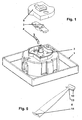
- FIG. 1 shows a basic illustration of the components of the contact protection device shown according to a first embodiment. It is the back of one Socket insert 1 (C-washer) of an earthed socket can be seen, whereby a contact protection lower part 2 is formed on this rear side - preferably molded in one piece - is.
- a contact protection lower part 2 is formed on this rear side - preferably molded in one piece - is.
- a rotary valve 3 - generally a protective slide - and a return spring designed as a leaf spring 4 introduced in the lower part 2.
- the leaf spring 4 is movable between Inner wall of the lower part 2 and the rotary valve 3 arranged.
- a touch protection cover that can be placed on the lower part 2 and snapped on 5 serves to close the contact protection device.
- the contact protection device according to FIG. 1 is in the closed position. d. H. without inserted pins of a connector - shown.
- the rotary valve 3 is rotatable on a central part in the lower part of the contact protection 2 pin 6 located.
- Locking connection 7 is used to lock the touch protection cover in place 5.
- the leaf spring 4 is at one end by inside the lower part of the contact protection 2 arranged ribs 8 fixed. The free end of the leaf spring 4 presses resiliently against the rotary valve 3 in such a way that the plug insert 1 introduced plug openings for the insertion of plug pins of a plug by means of of the rotary valve 3 are closed.
- FIG. 3 shows the contact protection device according to FIG. 1 in the open position.
- the spring force of the leaf spring 4 is pivoted about the pin 6, so that the plug openings 11 are exposed.
- the rotary movement of the rotary valve 3 slides an end rounding 10 of the leaf spring 4 along a stepped edge 9 of the Rotary slide valve 3. This inevitably becomes during the rotary movement adjusting friction between leaf spring 4 and rotary valve 3 is reduced.
- the Leaf spring 4 is not attached to the lower part 2, but to the rotary valve 3 (inserted) - for example via suitable ribs - and with their free Resilient end against the wall (or against a stepped edge of this wall) of the contact protection lower part 2 presses.
- FIG. 4 is a view of the rear of the socket insert 1 with a touch protection device first embodiment shown. It is the special design of the lower part 2 with a central pin 6, snap-in connection 7, ribs 8 and connector openings 11 can be seen. Between the side wall of the lower part of the contact protection 2 and the ribs 8 is a recess 12 for receiving a Angling the leaf spring 4 is provided.
- Fig. 5 is a return spring designed as a leaf spring 4 of the contact protection device first embodiment shown.
- the Leaf spring 4 has a rounded portion 10 at one end and at its opposite end End an angling 14 serving for fixation, which in the inserted state prevents shifting in the longitudinal direction.
- a taper 13 serves to even out the stress distribution occurring during the bending within the leaf spring 4.
- a touch protection cover 5 of the touch protection device is first Embodiment shown.
- the outer contour of the contact protection cover 5 is the outer contour of the contact protection lower part 2 adapted and engages snapping over this outer contour.
- FIG. 7 shows a view of the top of a rotary valve 3.
- They are one central bore suitable for engagement of the pin 6 of the contact protection lower part 2 17 and the offset edge 9 serving to reduce friction.
- two opposing cams 18 are provided in addition to the central bore 17 and perpendicular to the longitudinal axis of the rotary valve 3 . Set these cams 18 a defined minimum distance between rotary valve 3 and contact protection cover 5 sure. This causes the rotary valve to rock in its longitudinal direction with rotary valve 3 loaded on one side.
- FIG. 8 shows a view of the underside of a rotary valve 3.
- These engagement troughs 19 are each called “inclined planes" trained to the rotary movement of the rotary valve 3 when engaging connector pins initiate and implement.
- the engagement troughs 19 are each on the edge offset edges 20 provided.
- rotary valve 3 - d loaded on one side. H. just one of the two engagement troughs 19 presses through one of the plug openings 11 inserted pin - the rotary slide 3 tilts or tilts over the aforementioned Cam 18 so that one of the offset edges 20 into the free connector opening 11 engages and locked there. A rotary movement of the rotary valve 3 is thus effectively prevented and the plug openings remain closed.
- the lower part is a protection against accidental contact 2, the rotary valve 3 and the touch protection cover 4 symmetrical design - see for example the double ribs 8 or the duplicate offset edges 9, which has the great advantage that at Fully automatic assembly of the contact protection device or the installation device there is no need to pay attention to the special alignment of these parts.
- FIG. 9 is a touch protection device according to a second embodiment shown. It is the back of a socket insert 21 (C disc) one Earthing contact socket can be recognized, with a lower part on the back protecting against accidental contact 22 is formed - preferably integrally formed.
- a linear slide 23 generally a protective slide - and a return spring designed as a V-shaped leaf spring 24 in the lower part of the contact protection 22 introduced.
- the leaf spring 24 is movable between the inner wall of the contact protection lower part 22 and the linear slide 23.
- a on the touch protection lower part 22 attachable and snap-on touch protection cover (not shown) serves to close the contact protection device.
- the linear slide 23 is longitudinally movable on a central in the Touch protection lower part 22 located pin 25, this pin 25 engages in a central opening 28 of the linear slide 23.
- side walls 29 of the linear slide are longitudinal Side walls of the contact protection lower part 22 out.
- One at the end of this Pin 25 arranged locking connection 26 is used to lock the touch protection cover.
- the leaf spring 24 is in its middle section ribs 27 arranged within the contact protection lower part 2 are centered. The two Ends of the leaf spring 24 press resiliently against the linear slide 3 that thereby introducing the plug openings in the socket insert 21 of plug pins of a plug are closed by means of the linear slide 23.
- cams 36, 37 are provided, wherein two cams 37 lie opposite one another symmetrically. These cams 36, 37 provide one defined minimum distance between linear slide 23 and contact protection cover for sure. This causes the linear slide 23 to rock or tilt transverse to its longitudinal direction (direction of longitudinal movement) with one-sided loading Linear slide 23 allows.
- Fig. 10 is a return spring designed as a leaf spring of the contact protection device shown according to the second embodiment.
- the symmetrically designed leaf spring 24 has roundings 30 at both ends, which are low-friction Allow sliding along the end face of the linear slide 23.
- Rejuvenation 31 on both sides of the central contact surface 32 of the leaf spring serve to equalize the stress distribution occurring during the bending within the leaf spring 24.
- the symmetrical design of the leaf spring 24 facilitates assembly because of the correct alignment does not have to be observed.
- FIG. 11 is a view of the underside of a linear slide 23 of the contact protection device shown according to the second embodiment. They are on both sides central opening 28 arranged engagement troughs 33 for the plug pins of a plug to recognize. These engagement troughs 33 are each formed as "inclined planes", around the linear movement of the linear slide 3 with engaging connector pins initiate and implement.
- the engagement recesses 33 are each offset on the edge Provide edges 34. With linear slide 23 - d loaded on one side. H. only for one of the two engagement troughs 33 presses one inserted through one of the plug openings Pin - the linear slide 23 tilts or tilts over those mentioned above Cam 36, 37 so that one of the offset edges 34 engages in the free connector opening and locked there. A linear movement of the linear slide 23 is thus effective prevented and the plug openings remain closed.
- a rotary movement of the linear slide 23 is caused by the guidance of the side walls 29 prevented within the contact protection lower part 22.
- Ways serve on the underside of the linear slide 23 and in corresponding Troughs of the contact protection lower part 22 guided cams 35 of the precise Guiding the linear slide 23 during a longitudinal movement and the binding of rotary movements of the linear slide.
- leaf springs 4, 24 separate, to be inserted (preferably from spring steel existing) components.
- this Leaf springs 4 or 24 it is also possible to use this Leaf springs 4 or 24 as insert parts (made of spring steel) directly on the rotary valve 3 or to the lower part 2 or directly to the linear slide 23 or to be injected onto the lower contact protection part 22. This has the big one
- the advantage of handling only one component instead of two components during assembly is what is particularly important for fully automatic assembly.
- the leaf springs 4, 24 can be made of the same plastic material form, from which also the rotary slide 3 or the linear slide 23 or the Touch protection lower parts 2, 22 exist, d. H. the leaf spring is in one piece on Protective slide or lower part molded. There is also 2-component technology (Two-component injection molding) usable, d. H. the leaf spring 4, 24 is also molded in one piece on the protective slide or lower part, but consists of another, optimized with regard to the desired resilient properties Plastic material.
Landscapes
- Connector Housings Or Holding Contact Members (AREA)
- Cable Accessories (AREA)
- Connecting Device With Holders (AREA)
- Emergency Protection Circuit Devices (AREA)
Abstract
Description
- Fig.1
- eine prinzipielle Darstellung der Komponenten der Berührungsschutzvorrichtung gemäß einer ersten Ausführungsform,
- Fig. 2
- die Berührungsschutzvorrichtung gemäß Fig. 1 in geschlossener Position,
- Fig. 3
- die Berührungsschutzvorrichtung gemäß Fig. 1 in geöffneter Position,
- Fig. 4
- eine Sicht auf die Rückseite eines Steckdoseneinsatzes mit Berührungsschutzvorrichtung erster Ausführungsform,
- Fig. 5
- eine Blattfeder der Berührungsschutzvorrichtung erster Ausführungsform,
- Fig. 6
- eine Berührungsschutz-Abdeckung der Berührungsschutzvorrichtung erster Ausführungsform,
- Fig. 7
- eine Sicht auf die Oberseite eines Drehschiebers,
- Fig. 8
- eine Sicht auf die Unterseite eines Drehschiebers,
- Fig. 9
- eine Berührungsschutzvorrichtung gemäß einer zweiten Ausführungsform,
- Fig. 10
- eine Blattfeder der Berührungsschutzvorrichtung gemäß zweiter Ausführungsform,
- Fig. 11
- eine Sicht auf die Unterseite eines Linearschiebers der Berührungsschutzvorrichtung gemäß zweiter Ausführungsform.
Claims (14)
- Berührungsschutzvorrichtung für einen Steckdoseneinsatz einer Schutzkontakt-Steckdose, wobei an der Rückseite des Steckdoseneinsatzes (1, 21) ein Berührungsschutz-Unterteil (2, 22) ausgebildet ist, in welchem ein federbelasteter Schutzschieber eingebracht ist, welcher die im Steckdoseneinsatz eingebrachten Steckeröffnungen (11) zur Einführung von Steckerstiften eines Steckers verschließt und diese Steckeröffnungen lediglich bei gleichzeitigem Eingriff beider Steckerstifte öffnet, dadurch gekennzeichnet, daß eine Blattfeder (4, 24) als Rückstellfeder des Schutzschiebers (3, 23) dient und beweglich zwischen der Innenwandung des Berührungsschutz-Unterteils (2, 22) und dem Schutzschieber (3, 23) angeordnet ist.
- Berührungsschutzvorrichtung nach Anspruch 1, dadurch gekennzeichnet, daß die Blattfeder (4, 24) als separat einzulegendes, vorzugsweise aus Federstahl bestehendes Bauteil ausgebildet ist.
- Berührungsschutzvorrichtung nach Anspruch 1, dadurch gekennzeichnet, daß die Blattfeder (4, 24) als vorzugsweise aus Federstahl bestehendes, eingespritztes Insert-Teil des Berührungsschutz-Unterteils (2, 22) bzw. des Schutzschiebers (3, 23) ausgebildet ist.
- Berührungsschutzvorrichtung nach Anspruch 1, dadurch gekennzeichnet, daß die Blattfeder (4, 24) einstückig am Berührungsschutz-Unterteil (2, 22) bzw. am Schutzschieber (3, 23) angeformt ist.
- Berührungsschutzvorrichtung nach Anspruch 4, dadurch gekennzeichnet, daß die Blattfeder (4, 24) aus dem Kunststoffmaterial des Berührungsschutz-Unterteils (2, 22) bzw. des Schutzschiebers (3, 23) besteht.
- Berührungsschutzvorrichtung nach Anspruch 4, dadurch gekennzeichnet, daß die Blattfeder (4, 24) aus einem Kunststoffmaterial besteht, welches unterschiedlich zum Kunststoffmaterial des Berührungsschutz-Unterteils (2, 22) bzw. des Schutzschiebers (3, 23) ist.
- Berührungsschutzvorrichtung nach einem der vorstehenden Ansprüche, dadurch gekennzeichnet, daß die Blattfeder (4, 24) eine Verjüngung (13, 31) zur Vergleichmäßigung der Spannungsverteilung im Bauteil aufweist.
- Berührungsschutzvorrichtung nach einem der vorstehenden Ansprüche, dadurch gekennzeichnet, daß der Schutzschieber als Drehschieber (3) ausgebildet ist, welcher über seine Zentralbohrung (17) drehbeweglich auf einem zentral im Berührungsschutz-Unterteil (2) befindlichen Zapfen (6) aufgesetzt ist.
- Berührungsschutzvorrichtung nach mindestens einem der Ansprüche 1 bis 7, dadurch gekennzeichnet, daß der Schutzschieber als Linearschieber (23) ausgebildet ist.
- Berührungsschutzvorrichtung nach einem der vorstehenden Ansprüche, dadurch gekennzeichnet, daß ein Abschnitt der Blattfeder (4, 24) - insbesondere eine Abwinkelung (14) - durch Rippen (8, 27) fixiert ist, welche eine Aussparung (12) zur Aufnahme dieses Abschnitts der Blattfeder bilden.
- Berührungsschutzvorrichtung nach einem der vorstehenden Ansprüche, dadurch gekennzeichnet, daß zumindest ein abgerundeter Abschnitt (10, 30) der Blattfeder (4, 24) längs einer die Reibung vermindernde, abgesetzten Kante (9) gleitet.
- Berührungsschutzvorrichtung nach einem der vorstehenden Ansprüche, dadurch gekennzeichnet, daß der Schutzschieber (3, 23) als schiefe Ebenen ausgebildete Eingriffsmulden (19, 33) für den Eingriff der Steckerstifte aufweist.
- Berührungsschutzvorrichtung nach Anspruch 12, dadurch gekennzeichnet, daß der Schutzschieber (3, 23) zumindest einen Nocken (18, 36, 37) aufweist, über den er bei einseitiger Belastung lediglich einer Steckeröffnung derart kippt, daß eine randseitig der Eingriffsmulden (19, 33) angeordnete abgesetzte Kante (20, 34) in die nicht vom Steckerstift beaufschlagte Steckeröffnung eingreift und dort verrastet.
- Berührungsschutzvorrichtung nach einem der vorstehenden Ansprüche, dadurch gekennzeichnet, daß eine aufrastbare Berührungsschutz-Abdeckung (5) zum Verschluß der Berührungsschutzvorrichtung dient, wobei diese Berührungsschutz-Abdeckung Steckeröffnungen (15) für die Steckerstifte aufweist.
Applications Claiming Priority (2)
| Application Number | Priority Date | Filing Date | Title |
|---|---|---|---|
| DE10148287A DE10148287A1 (de) | 2001-09-29 | 2001-09-29 | Berührungsschutzvorrichtung für eine Schutzkontakt-Steckdose |
| DE10148287 | 2001-09-29 |
Publications (3)
| Publication Number | Publication Date |
|---|---|
| EP1298763A2 true EP1298763A2 (de) | 2003-04-02 |
| EP1298763A3 EP1298763A3 (de) | 2004-07-07 |
| EP1298763B1 EP1298763B1 (de) | 2005-06-01 |
Family
ID=7700898
Family Applications (1)
| Application Number | Title | Priority Date | Filing Date |
|---|---|---|---|
| EP02019610A Expired - Lifetime EP1298763B1 (de) | 2001-09-29 | 2002-09-03 | Berührungsschutzvorrichtung für eine Schutzkontakt-Steckdose |
Country Status (4)
| Country | Link |
|---|---|
| EP (1) | EP1298763B1 (de) |
| AT (1) | ATE297061T1 (de) |
| DE (2) | DE10148287A1 (de) |
| NO (1) | NO20024652L (de) |
Cited By (1)
| Publication number | Priority date | Publication date | Assignee | Title |
|---|---|---|---|---|
| US20150372410A1 (en) * | 2014-06-20 | 2015-12-24 | Hubbell Incorporated | Tamper resistant receptacle with propeller shutter |
Families Citing this family (4)
| Publication number | Priority date | Publication date | Assignee | Title |
|---|---|---|---|---|
| DE102004021969A1 (de) * | 2004-05-04 | 2005-12-01 | Abb Patent Gmbh | Berührungsschutz einer Steckdose mit einem federbelasteten Schutzschieber |
| DE102004021971B3 (de) * | 2004-05-04 | 2005-09-15 | Abb Patent Gmbh | Steckdoseeinsatz einer Steckdose mit Berührungsschutz |
| DE102004021970B3 (de) * | 2004-05-04 | 2005-09-15 | Abb Patent Gmbh | Steckdose mit Drehschieber-Berührungsschutz-Baueinheit |
| DE102005011435B4 (de) * | 2005-03-12 | 2006-11-23 | Abb Patent Gmbh | Steckdoseneinsatz einer Steckdose mit erhöhtem Berührungsschutz |
Family Cites Families (5)
| Publication number | Priority date | Publication date | Assignee | Title |
|---|---|---|---|---|
| DE914991C (de) * | 1939-07-29 | 1954-07-12 | Leopold Kostal Elektrotechn Sp | Steckdose mit Verriegelungseinrichtung |
| DE836369C (de) * | 1951-03-02 | 1952-04-10 | Max Kirmis | Beruehrungsschutzvorrichtung fuer Steckdosen |
| FR2547119A1 (fr) * | 1983-05-30 | 1984-12-07 | Poinsignon Raphael | Cache-prise semi-automatique |
| IT1275269B (it) * | 1995-05-29 | 1997-08-05 | Bticino Spa | Dispositivo otturatore di alveoli di presa di corrente |
| US6217353B1 (en) * | 1999-12-01 | 2001-04-17 | Aurise Inc. | Structure of a safety receptacle |
-
2001
- 2001-09-29 DE DE10148287A patent/DE10148287A1/de not_active Withdrawn
-
2002
- 2002-09-03 DE DE50203250T patent/DE50203250D1/de not_active Expired - Fee Related
- 2002-09-03 EP EP02019610A patent/EP1298763B1/de not_active Expired - Lifetime
- 2002-09-03 AT AT02019610T patent/ATE297061T1/de not_active IP Right Cessation
- 2002-09-27 NO NO20024652A patent/NO20024652L/no not_active Application Discontinuation
Cited By (1)
| Publication number | Priority date | Publication date | Assignee | Title |
|---|---|---|---|---|
| US20150372410A1 (en) * | 2014-06-20 | 2015-12-24 | Hubbell Incorporated | Tamper resistant receptacle with propeller shutter |
Also Published As
| Publication number | Publication date |
|---|---|
| DE50203250D1 (de) | 2005-07-07 |
| EP1298763B1 (de) | 2005-06-01 |
| EP1298763A3 (de) | 2004-07-07 |
| DE10148287A1 (de) | 2003-04-17 |
| ATE297061T1 (de) | 2005-06-15 |
| NO20024652D0 (no) | 2002-09-27 |
| NO20024652L (no) | 2003-03-31 |
Similar Documents
| Publication | Publication Date | Title |
|---|---|---|
| DE102004038123B4 (de) | Elektrischer Stecker und elektrische Steckeraufnahme | |
| DE68914560T2 (de) | Steckverbinder mit Verriegelungsmechanismus. | |
| DE4408985B4 (de) | Elektrische Einrichtung, insbesondere Reihenklemme, mit einer Klemme für eine Schnellverbindung | |
| DE102006016882A1 (de) | Steckverbinder | |
| DE19708609C2 (de) | Schiebeschalter | |
| DE4420546A1 (de) | Gehäuseelement für elektrische Verbinder | |
| DE102021101505A1 (de) | Leiteranschlussklemme | |
| DE10202341C1 (de) | Berührungsschutzvorrichtung für eine Schutzkontakt-Steckdose mit federbelastetem Drehschieber | |
| EP1298763A2 (de) | Berührungsschutzvorrichtung für eine Schutzkontakt-Steckdose | |
| DE3816909C2 (de) | ||
| DE4410950C2 (de) | Elektrischer Verbinder mit Primär- und Sekundärverriegelung der Kontaktelemente | |
| DE102014107080A1 (de) | Haltevorrichtung sowie Stift zur Anordnung in einer solchen Haltevorrichtung | |
| DE10216209C1 (de) | Berührungsschutzvorrichtung mit Längsschieber für eine elektrische Steckdose | |
| DE10203894C1 (de) | Schutzkontaktsteckdose mit am Steckdosensockel befestigter Berührungsschutzvorrichtung | |
| DE10202342C1 (de) | Berührungsschutzvorrichtung für eine Schutzkontakt-Steckdose unter Einsatz eines Längsschiebers mit direkt angespitzter Rückstellfeder | |
| DE19532623A1 (de) | Elektrischer Stecker mit einem Betätigungsschieber | |
| DE9311448U1 (de) | Lampenfassung für eine Niederspannungslampe mit zwei Steckerstiften | |
| DE10225562C1 (de) | Steckdoseneinsatz einer Steckdose mit in einer Berührungsschutzvorrichtung geführtem Längsschieber | |
| BE1030843A1 (de) | Crimpadapter, Crimpanordnung und Steckverbinder | |
| DE10315557B3 (de) | Steckdoseneinsatz einer Steckdose mit in einer Berührungsschutzvorrichtung geführtem Schieber | |
| DE10225564C1 (de) | Steckdoseneinsatz einer Steckdose mit in einer Berührungsschutzvorrichtung geführtem Drehschieber | |
| DE10225563C1 (de) | Steckdoseneinsatz einer Steckdose mit in einer Berührungsschutzvorrichtung geführtem Drehschieber | |
| EP1471608A2 (de) | Steckdoseneinsatz einer Steckdose mit in einer Berührungsschutzvorrichtung geführtem Längsschieber | |
| DE10216208C1 (de) | Berührungsschutzvorrichtung für eine elektrische Steckdose | |
| DE19602293B4 (de) | Verriegelungsmechanismus für eine elektrische Steckverbinderanordnung |
Legal Events
| Date | Code | Title | Description |
|---|---|---|---|
| PUAI | Public reference made under article 153(3) epc to a published international application that has entered the european phase |
Free format text: ORIGINAL CODE: 0009012 |
|
| AK | Designated contracting states |
Kind code of ref document: A2 Designated state(s): AT BE BG CH CY CZ DE DK EE ES FI FR GB GR IE IT LI LU MC NL PT SE SK TR Designated state(s): AT BE BG CH CY CZ DE DK EE ES FI FR GB GR IE IT LI LU MC NL PT SE SK TR |
|
| AX | Request for extension of the european patent |
Extension state: AL LT LV MK RO SI |
|
| PUAL | Search report despatched |
Free format text: ORIGINAL CODE: 0009013 |
|
| AK | Designated contracting states |
Kind code of ref document: A3 Designated state(s): AT BE BG CH CY CZ DE DK EE ES FI FR GB GR IE IT LI LU MC NL PT SE SK TR |
|
| AX | Request for extension of the european patent |
Extension state: AL LT LV MK RO SI |
|
| 17P | Request for examination filed |
Effective date: 20040727 |
|
| 17Q | First examination report despatched |
Effective date: 20040930 |
|
| GRAP | Despatch of communication of intention to grant a patent |
Free format text: ORIGINAL CODE: EPIDOSNIGR1 |
|
| GRAS | Grant fee paid |
Free format text: ORIGINAL CODE: EPIDOSNIGR3 |
|
| AKX | Designation fees paid |
Designated state(s): AT DE FI NL SE |
|
| GRAA | (expected) grant |
Free format text: ORIGINAL CODE: 0009210 |
|
| AK | Designated contracting states |
Kind code of ref document: B1 Designated state(s): AT DE FI NL SE |
|
| PG25 | Lapsed in a contracting state [announced via postgrant information from national office to epo] |
Ref country code: FI Free format text: LAPSE BECAUSE OF FAILURE TO SUBMIT A TRANSLATION OF THE DESCRIPTION OR TO PAY THE FEE WITHIN THE PRESCRIBED TIME-LIMIT Effective date: 20050601 |
|
| REF | Corresponds to: |
Ref document number: 50203250 Country of ref document: DE Date of ref document: 20050707 Kind code of ref document: P |
|
| PG25 | Lapsed in a contracting state [announced via postgrant information from national office to epo] |
Ref country code: SE Free format text: LAPSE BECAUSE OF FAILURE TO SUBMIT A TRANSLATION OF THE DESCRIPTION OR TO PAY THE FEE WITHIN THE PRESCRIBED TIME-LIMIT Effective date: 20050901 |
|
| PLBE | No opposition filed within time limit |
Free format text: ORIGINAL CODE: 0009261 |
|
| STAA | Information on the status of an ep patent application or granted ep patent |
Free format text: STATUS: NO OPPOSITION FILED WITHIN TIME LIMIT |
|
| 26N | No opposition filed |
Effective date: 20060302 |
|
| PGFP | Annual fee paid to national office [announced via postgrant information from national office to epo] |
Ref country code: AT Payment date: 20060914 Year of fee payment: 5 |
|
| PGFP | Annual fee paid to national office [announced via postgrant information from national office to epo] |
Ref country code: NL Payment date: 20060915 Year of fee payment: 5 |
|
| PGFP | Annual fee paid to national office [announced via postgrant information from national office to epo] |
Ref country code: DE Payment date: 20060926 Year of fee payment: 5 |
|
| PG25 | Lapsed in a contracting state [announced via postgrant information from national office to epo] |
Ref country code: NL Free format text: LAPSE BECAUSE OF NON-PAYMENT OF DUE FEES Effective date: 20080401 |
|
| NLV4 | Nl: lapsed or anulled due to non-payment of the annual fee |
Effective date: 20080401 |
|
| PG25 | Lapsed in a contracting state [announced via postgrant information from national office to epo] |
Ref country code: AT Free format text: LAPSE BECAUSE OF NON-PAYMENT OF DUE FEES Effective date: 20070903 |
|
| PG25 | Lapsed in a contracting state [announced via postgrant information from national office to epo] |
Ref country code: DE Free format text: LAPSE BECAUSE OF NON-PAYMENT OF DUE FEES Effective date: 20080401 |