EP1296084B1 - Exzentrisches oszillierendes Untersetzungsgetriebe - Google Patents
Exzentrisches oszillierendes Untersetzungsgetriebe Download PDFInfo
- Publication number
- EP1296084B1 EP1296084B1 EP02020675A EP02020675A EP1296084B1 EP 1296084 B1 EP1296084 B1 EP 1296084B1 EP 02020675 A EP02020675 A EP 02020675A EP 02020675 A EP02020675 A EP 02020675A EP 1296084 B1 EP1296084 B1 EP 1296084B1
- Authority
- EP
- European Patent Office
- Prior art keywords
- outer casing
- input shaft
- pinions
- gear
- speed reducer
- Prior art date
- Legal status (The legal status is an assumption and is not a legal conclusion. Google has not performed a legal analysis and makes no representation as to the accuracy of the status listed.)
- Expired - Lifetime
Links
Images


Classifications
-
- F—MECHANICAL ENGINEERING; LIGHTING; HEATING; WEAPONS; BLASTING
- F16—ENGINEERING ELEMENTS AND UNITS; GENERAL MEASURES FOR PRODUCING AND MAINTAINING EFFECTIVE FUNCTIONING OF MACHINES OR INSTALLATIONS; THERMAL INSULATION IN GENERAL
- F16H—GEARING
- F16H1/00—Toothed gearings for conveying rotary motion
- F16H1/28—Toothed gearings for conveying rotary motion with gears having orbital motion
- F16H1/32—Toothed gearings for conveying rotary motion with gears having orbital motion in which the central axis of the gearing lies inside the periphery of an orbital gear
-
- F—MECHANICAL ENGINEERING; LIGHTING; HEATING; WEAPONS; BLASTING
- F16—ENGINEERING ELEMENTS AND UNITS; GENERAL MEASURES FOR PRODUCING AND MAINTAINING EFFECTIVE FUNCTIONING OF MACHINES OR INSTALLATIONS; THERMAL INSULATION IN GENERAL
- F16H—GEARING
- F16H1/00—Toothed gearings for conveying rotary motion
- F16H1/28—Toothed gearings for conveying rotary motion with gears having orbital motion
- F16H1/46—Systems consisting of a plurality of gear trains each with orbital gears, i.e. systems having three or more central gears
-
- F—MECHANICAL ENGINEERING; LIGHTING; HEATING; WEAPONS; BLASTING
- F16—ENGINEERING ELEMENTS AND UNITS; GENERAL MEASURES FOR PRODUCING AND MAINTAINING EFFECTIVE FUNCTIONING OF MACHINES OR INSTALLATIONS; THERMAL INSULATION IN GENERAL
- F16H—GEARING
- F16H1/00—Toothed gearings for conveying rotary motion
- F16H1/28—Toothed gearings for conveying rotary motion with gears having orbital motion
- F16H1/32—Toothed gearings for conveying rotary motion with gears having orbital motion in which the central axis of the gearing lies inside the periphery of an orbital gear
- F16H2001/323—Toothed gearings for conveying rotary motion with gears having orbital motion in which the central axis of the gearing lies inside the periphery of an orbital gear comprising eccentric crankshafts driving or driven by a gearing
Definitions
- the present invention relates to an eccentric oscillating-type speed reducer according to the preamble of claim 1.
- the present invention relates to an eccentric oscillating-type speed reducer for effecting speed reduction by eccentrically rotating pinions.
- Such a device according to the preamble of claim 1 is known from US-A-3 994 187 .
- the present applicant proposed in Japanese Patent Application No. 2000-202030 an eccentric oscillating-type speed reducer which makes it possible to make the manufacturing cost low and make the assembling operation simple by forming a plurality of pinions by pinions of the same shape.
- This eccentric oscillating-type speed reducer is comprised of an outer casing having internal teeth formed on its inner periphery; a plurality of pinions which are accommodated in the outer casing, which have on their outer peripheries external teeth meshing with the internal teeth, the number of the external teeth being slightly smaller than that of the internal teeth, and which are juxtaposed in parallel in an axial direction; an even number of not less than four crankshafts which are arranged in such a manner as to be spaced apart from each other at equal angles in a circumferential direction, central portions of the crankshafts being inserted in the pinions, so as to eccentrically rotate the pinions as the crankshafts rotate; a carrier which is inserted in the outer casing for rotatably supporting both end portions of the crankshafts; an input shaft supported rotatably by the outer casing and having a driving external gear coaxial with the internal teeth; and driven external gears respectively mounted on the crankshafts and meshing with the driving external gear while surrounding the driving external gear
- the object of the invention is to provide an eccentric oscillating-type speed reducer which makes it possible to make a final speed reduction ratio and a final output torque substantially large by enlarging the reduction ratio based on the driving and driven external gears.
- an eccentric oscillating-type speed reducer including an outer casing having internal teeth formed on an inner periphery thereof; a plurality of pinions which are accommodated in the outer casing, which have on outer peripheries thereof external teeth meshing with the internal teeth, the number of the external teeth being slightly smaller than that of the internal teeth, and which are juxtaposed in parallel in an axial direction; an even number of not less than four crankshafts which are arranged in such a manner as to be spaced apart from each other at equal angles in a circumferential direction, central portions of the crankshafts being inserted in the pinions, so as to eccentrically rotate the pinions as the crankshafts rotate; a carrier which is inserted in the outer casing for rotatably supporting both end portions of the crankshafts; an input shaft supported rotatably by the outer casing and having a driving external gear coaxial with the internal teeth; and driven external gears respectively mounted on the crankshafts and meshing with the driving external gear while
- the driven external gears are classified into a plurality of paired-gear groups each consisting of two driven external gears spaced apart from each other by 180 degrees in the circumferential direction, axial positions of the two driven external gears making up each of the paired-gear groups with respect to the input shaft are made identical, and a different paired-gear group is arranged by being offset in the axial direction of the input shaft. Therefore, only two driven external gears making up the paired-gear group are present at an identical axial position of the input shaft. Consequently, even if the diameters of these driven external gears are made large up to the very limit, these driven external gears do not interfere with each other. Accordingly, it is possible to readily enlarge the reduction ratio based on the driving and driven external gears, with the result that it is possible to substantially enlarge the final reduction ratio without lowering the final output torque in the eccentric oscillating-type speed reducer.
- the bearing and the seal member interposed between the outer casing and the input shaft can be lubricated by the lubricating oil filled in the sealed space, so that a lubricating device for lubricating the bearing and the seal member or the operation for replenishing the lubricating oil are made unnecessary.
- reference numeral 11 denotes a substantially cylindrical cylinder whose central axis extends in a perpendicular direction (vertical direction), and this cylinder 11 is attached to a fixing frame of an unillustrated wind-power generating facility.
- Numeral 12 denotes a plurality of internal tooth pins 13 serving as internal teeth provided on an inner periphery of a central portion of the cylinder 11, and these internal tooth pins 13 extend in the axial direction, and are arranged in such a manner as to be spaced apart from each other at equal angles in the circumferential direction.
- a stepped cylindrical upper cover 14 with a bottom for closing an opening in an upper end of the cylinder 11 is fixed to the upper end of the cylinder 11, and a substantially cylindrical extension 14a for supporting a drive motor, which will be described later, is formed on an upper surface of this upper cover 14.
- the aforementioned cylinder 11 and the upper cover 14 as a whole form an outer casing 15 on an inner periphery of which internal teeth (internal tooth pins 13) are formed and whose lower end is open, and the upper cover 14 forms an upper wall of the outer casing 15.
- Reference numerals 17 and 18 denote a plurality of, two in the illustrated case, pinions which are accommodated in the outer casing 15, and these pinions 17 and 18 are juxtaposed in such a manner as to be spaced apart from each other in the axial direction (in the vertical direction).
- Each of these pinions 17 and 18 has on its outer periphery outer teeth 17a, 18a whose numbers of teeth are slightly smaller than the number of teeth of the internal toothpins 13, i.e., smaller by one in the illustrated case.
- These adjacent pinions 17 and 18 mesh with the internal tooth pins 13 of the cylinder 11 in a state in which their phases are offset from each other by 180 degrees.
- Numeral 20 denotes a carrier whose upper end portion and central portion are inserted in the aforementioned outer casing 15 and whose lower end portion projects downward from the outer casing 15.
- This carrier 20 is rotatably supported by the outer casing 15 by means of a pair of bearings 21 which are spaced apart in the vertical direction (axial direction).
- the carrier 20 has a base portion 22 located on the lower side (one side) than the pinions 17 and 18, as well as a disk-shaped end plate portion 23 located on an upper side (the other end side) than the pinions 17 and 18.
- the carrier 20 has column portions 24 formed integrally on the base portion 22 and each having a substantially triangular cross section and extending axially from an upper surface thereof (the other side surface) toward the end plate portion 23. These column portions 24 are provided in an even number of not less than four, four in the illustrated case, and are arranged in such a manner as to be spaced apart from each other at equal angles in the circumferential direction.
- reference numeral 25 denotes a prepared hole extending downward from the upper surface (other side surface) of each column portion 24.
- Each of these prepared holes 25 extends through the column portion 24 of the carrier 20, and its bottom surface (lower end) is located inside the base portion 22.
- a plurality of bolts 26 which are inserted in the end plate portion 23 are respectively screwed into the prepared holes 25 thus formed in the column portions 24 and the base portion 22.
- the end plate portion 23 and the column portions 24 are fastened together by the bolts 26, allowing the end plate portion 23 to be fastened to the column portions 24.
- tips (lower ends) of these bolts 26 are also located closer to the base portion 22 side than proximal ends (lower ends) of the column portions 24 in the same way as the prepared holes 25. Consequently, a space 28 formed between the bottom of the prepared hole 25 and the tip of the bolt 26 is located in the base portion 22.
- reference numeral 27 denotes a positioning pin inserted in both the end plate portion 23 and the column portion 24.
- the entire column portion 24 assumes a solid structure, thereby increasing the strength and permitting the output of high torque.
- loosely fitting holes 30 and 31 having substantially triangular cross sections and provided in numbers (four) equivalent to those of the column portions 24 are respectively formed in the pinions 17 and 18 in such a manner as to be spaced apart from each other in the circumferential direction.
- the column portions 24 of the carrier 20 are respectively passed through the loosely fitting holes 30 and 31 of these pinions 17 and 18 in the axial direction in a loosely fitted state.
- the above-described base portion 22, end plate portion 23, column portions 24, and bolts 6 as a whole constitute the carrier 20.
- through holes 34 and 35 which are spaced apart at equal angles in the circumferential direction are respectively formed in the pinions 17 and 18, and these through holes 34 and 35 are formed in numbers identical to the number of the column portions 24, i.e., four in the illustrated case. Further, these through holes 34 and 35 are disposed at circumferentially intermediate points between adjacent ones of the through holes 30 and 31.
- Reference numeral 37 denotes crankshafts provided in an even number of not less than four, i.e., in a number (four) identical to those of the through holes 34 and 35 in the illustrated case, and these crankshafts 37 are arranged in such a manner as to be spaced apart from each other at equal angles in the circumferential direction. Lower end portions (one end portions) and upper end portions (other end portions) of these crankshafts 37 are rotatably supported by the base portion 22 and the end plate portion 23 of the carrier 20 by means of bearings 38 and 39, respectively.
- Each crankshaft 37 has in its axially central portion two eccentric portions 40 and 41 which are off-centered by an equidistance from the central axis of the crankshaft 37, and phases of these eccentric portions 40 and 41 are offset by 180 degrees in the circumferential direction. Further, these eccentric portions 40 and 41 are respectively inserted in the through holes 34 and 35 of the pinions 17 and 18 with roller bearings 42 interposed therebetween.
- reference numeral 45 denotes a drive motor which is fixed to an upper end of the extension 14a of the outer casing 15, and an intermediate shaft 47 which is passed through the center of the aforementioned upper cover 14 is connected to a lower end of an output shaft 46 extending vertically from the drive motor 45. Further, a bearing 48 is interposed between this intermediate shaft 47 and the upper cover 14, thereby allowing the intermediate shaft 47 to be rotatably supported by the upper casing 15. Further, a sun gear 49 constituted by an external gear is formed at a lower end portion of this intermediate shaft 47.
- oil seals 50 and 51 serving as seal members are respectively interposed between the intermediate shaft 47 and the outer casing 15 (upper cover 14) and between a lower end of the outer casing 15 (cylinder 11) and the base portion 22 of the carrier 20. Consequently, a sealed space 52 is formed in the outer casing 15, and a lubricating oil 53 is filled in this sealed space 52.
- reference numeral 15a denotes an inlet for the lubricating oil 53 formed in the outer casing 15, and this inlet 15a is closed by a detachable cap 54.
- Reference numeral 55 denotes a rotating shaft disposed immediately below the intermediate shaft 47 while maintaining a coaxial relationship with the intermediate shaft 47. A lower end portion of this rotating shaft 55 is rotatably supported by the end plate portion 23 of the carrier 20 by means of a bearing 56.
- Numeral 57 denotes a disk-shaped connecting member attached to an upper end portion of the rotating shaft 55, and a plurality of pins 58 spaced apart from each other in the circumferential direction are fixed to this connecting member 57.
- Reference numeral 59 denotes an internal gear fixed to an inner periphery of the upper cover 14 opposing the sun gear 49, and a plurality of planetary gears 60 supported rotatably by the pins 58 mesh with this internal gear 59 and the sun gear 49.
- a planetary reduction gear mechanism 61 consisting of the intermediate shaft 47 having the sun gear 49, the connecting member 57, the pins 58, the internal gear 59, and the planetary gears 60, and is then transmitted to the rotating shaft 55.
- the above-described intermediate shaft 47 and rotating shaft 55 as a whole constitute an input shaft 62, and the aforementioned planetary reduction gear mechanism 61 serving as a front-stage reduction gear is interposed midway on this input shaft 62.
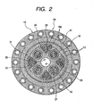
- the input shaft 62 specifically the rotating shaft 55, has a driving external gear 65 at its lower end portion, and a plurality of (four) driven external gears 66, which mesh with the driving external gear 65 while surrounding it, are arranged around this driving external gear 65.
- these driven external gears 66 are mounted on upper end portions of the respective crankshafts 37, with the result that these driven external gears 66 are arranged in such a manner as to be spaced apart from each other at equal angles, by 90 degrees in the illustrated case, in the circumferential direction.
- the driven external gears 66 are classified into a plurality of (two) paired-gear groups (pairs) 67, and each paired-gear group 67 consists of two driven external gears 66 spaced apart from each other by 180 degrees in the circumferential direction. Further, axial positions of the two driven external gears 66 making up each paired-gear group 67 with respect to the input shaft 62 are made identical; namely, these two driven external gears 66 mesh with the driving external gear 65 at the same axial position.
- the different paired-gear group 67 is arranged by being offset in the axial direction of the input shaft 62 (the driven external gears 66 belonging to the different paired-gear group 67 mesh with the driving external gear 65 at an axially spaced-apart position) Further, the driven external gears 66 of these two paired-gear groups 67 are spaced apart from each other by 90 degrees in the circumferential direction.
- the aforementioned outer casing 15, pinions 17 and 18, carrier 20, crankshafts 37, input shaft 62, driving external gear 65, and driven external gears 66 as a whole constitute an eccentric oscillating-type speed reducer 69.
- This eccentric oscillating-type speed reducer 69 is disposed vertically so that the input shaft 62 is located on the upper side.
- the eccentric oscillating-type speed reducer 69 Internal parts of the eccentric oscillating-type speed reducer 69, e.g., the pinions 17 and 18, the bearings 21, the crankshafts 37, and the like, are lubricated by the aforementioned lubricating oil 53.
- the bearing 48 and the oil seal 50 are also lubricated by this lubricating oil 53, so that a lubricating device for lubricating the bearing 48 and the oil seal 50 or the operation for replenishing the lubricating oil are made unnecessary.
- the arrangement provided is such that a portion of the upper wall (upper cover 14) of the outer casing 15 where the input shaft 62 is passed through is made to protrude upward, whereby this protruding portion 71 (an upper end portion of the sealed space 52) is located upwardly of the bearing 48 and the oil seal 50 between the input shaft 62 and the upper cover 14, and the oil level 53a of the lubricating oil 53 filled in the sealed space 52 is made to rise up to the protruding portion 71, i.e., is made to be located upwardly of the bearing 48 and the oil seal 50.
- the bearing 48 and the oil seal 50 are thereby lubricated.
- Reference numeral 75 denotes a transmission gear which is fixed to the carrier 20, specifically the base portion 22 projecting downward from the lower end of the outer casing 15.
- This transmission gear 75 meshes with an external gear which is fixed to a pivot of a wind-power generating facility.
- the rotation of the drive motor 45 which has been subjected to speed reduction by the above-described planetary reduction gear mechanism 61 and the eccentric oscillating-type speed reducer 69, is transmitted to the aforementioned pivot so as to allow a generator having the pivot and blades to swivel within a horizontal plane in correspondence with the wind direction, thereby improving the generating efficiency.
- the driven external gears 66 are classified into the plurality of paired-gear groups 67 each consisting of two driven external gears 66 spaced apart by 180 degrees in the circumferential direction, and the axial positions of the two driven external gears 66 making up each paired-gear group 67 with respect to the input shaft 62 are made identical, while the different paired-gear group 67 is arranged by being offset in the axial direction of the input shaft 62. Therefore, only the two driven external gears 66 making up each paired-gear group 67 are present at an identical axial position of the input shaft 62.
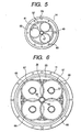
- a total of four driven external gears 66 consisting of two paired-gear groups 67 are provided, in this invention a total of six driven external gears 66 consisting of three paired-gear groups 67 may be provided, as shown in Fig. 7 .
- the paired-gear groups 67 are spaced apart from each other by 60 degrees in the circumferential direction, while being offset from each other in three stages in the axial direction of the input shaft 62.
- the outer casing 15 is set as the fixed side while the carrier 20 is set as the rotating side so as to output a low-speed rotation from the carrier 20 which is the rotating side
- the carrier may be set as the fixed side while the outer casing may be set as the rotating side so as to output a low-speed rotation from the outer casing which is the rotating side.
Claims (4)
- Exzentrischer oszillierender Drehzahlminderer (69), umfassend:ein äußeres Gehäuse (15) mit internen Zähnen (13), die auf dessen inneren Umfang gebildet sind;eine Vielzahl von Antriebsrädern (17, 18), die im äußeren Gehäuse (15) aufgenommen sind, an deren äußeren Umfängen externe Zähne (17a, 18a) aufweisen, die in die internen Zähne (13) eingreifen, wobei die Anzahl der externen Zähne (17a, 18a) leicht kleiner als die Anzahl der internen Zähne (13) ist, und wobei die Antriebsräder entlang einer Längsrichtung nebeneinander gestellt sind;eine gerade Anzahl, nicht weniger als vier, von Kurbelwellen (37), die mit gleichen Winkeln entlang einer Umfangsrichtung voneinander beabstandet sind, wobei zentrale Bereiche der Kurbelwellen (37) in den Antriebsrädern (17, 18) eingefügt sind, damit die Antriebsräder (17, 18) exzentrisch rotiert werden, wenn die Kurbelwellen (37) rotieren;einen Träger (20), der im äußeren Gehäuse (15) eingefügt ist, um beide Endabschnitte der Kurbelwellen (37) rotierbar abzustützen;eine Eingangsachse (62), die vom äußeren Gehäuse (15) rotierbar gestützt ist undein antreibendes externes Zahnrad (65) aufweist, das mit den internen Zähnen (13) gleichachsig ist;angetriebene externe Zahnräder (66), die jeweils auf den Kurbelwellen (37) montiert sind und in das antreibende externe Zahnrad (65) greift, während sie das antreibende externe Zahnrad (65) umgeben; unddadurch gekennzeichnet, dass
der Träger (20) umfasst:einen Grundabschnitt (22), der auf einer Seite der Zahnräder (17, 18) angeordnet ist;einen Seitenplattenabschnitt (23), die auf einer anderen Seite der Zahnräder (17, 18) angeordnet ist;
die angetriebenen externen Zahnräder (66) in einer Vielzahl von gepaarten Zahnradgruppen (67) klassifiziert sind, wobei jede Gruppe aus zwei angetriebenen externen Zahnrädern (66) besteht, die um 180 Grad entlang der Umfangsrichtung voneinander beabstandet sind;
Axialpositionen der zwei angetriebenen externen Zahnräder (66) derselben Gruppe in Bezug auf die Eingangsachse (62) identisch sind, während die angetriebenen externen Zahnräder (66) unterschiedlicher Gruppen entlang der Längsrichtung der Eingangsachse (62) voneinander versetzt sind; und
der Träger (20) weiterhin umfasst:eine Vielzahl von Spaltenabschnitten (24), die ganzheitlich mit dem Grundabschnitt (22) gebildet sind und sich in Richtung des Seitenplattenabschnittes (23) erstrecken, wobei zentrale Bereiche der Spaltenabschnitte (24) durch die Zahnräder (17, 18) durchgehen; undeine Vielzahl von Bolzen (26), die jeweils in Bohrungen (25) verschraubt sind, die in den Spaltenabschnitten (24) und dem Grundabschnitt (22) gebildet sind, damit der Seitenplattenabschnitt (23) mit den Spaltenabschnitten (24) befestigt ist,ein Ende jeder der Bolzen (26) näher an einer Seite des Grundabschnittes (22) als einem proximalen Ende jedes der Spaltenabschnitte (24) angeordnet ist; und ein Raum (28), der zwischen einem Boden jeder der Bohrungen (25) und dem Ende jeder der Bolzen (26) gebildet ist, im Grundabschnitt (22) angeordnet ist. - Exzentrischer oszillierender Drehzahlminderer (69) gemäß Anspruch 1, wobei:der exzentrische oszillierende Drehzahlminderer (69) vertikal angeordnet ist, sodass die Eingangsachse (62) an einer oberen Seite angeordnet ist;Lager (21) und Dichtelemente (50) jeweils zwischen dem äußeren Gehäuse (15) und dem Träger (20) und zwischen dem äußeren Gehäuse (15) und der Eingangsachse (62) angeordnet sind, damit ein gedichteter Raum (52) im äußeren Gehäuse (15) gebildet wird, der mit einem schmierenden Öl (53) gefüllt ist; undein Abschnitt einer oberen Wandung (14) des äußeren Gehäuses (15), durch die die Eingangsachse (62) durchgeht, in Bezug auf das Lager (48) und das Dichtelement (50), die zwischen dem äußeren Gehäuse (15) und der Eingangsachse (62) angeordnet sind, aufwärts gerichtet angeordnet ist, wodurch ein Ölpegel (53a) des schmierenden Öls (53) in Bezug auf das Lager und das Dichtelement (50), die zwischen dem äußeren Gehäuse (15) und der Eingangsachse (62) angeordnet sind, aufwärts gerichtet angeordnet ist.
- Exzentrischer oszillierender Drehzahlminderer (69) gemäß Anspruch 2, wobei ein Luftbehälter (62), der die Ausdehnung aufnimmt, wenn sich das schmierende Öl (53) ausdehnt, zwischen dem Ölpegel (53a) des schmierenden Öls (53) und der oberen Wandung (14) des äußeren Gehäuses (15) vorgesehen ist.
- Exzentrischer oszillierender Drehzahlminderer (69) gemäß einem der Ansprüche 1 bis 3, wobei ein Getrieberadsatz (75), der in ein Zahnrad greift, das mit einer Drehachse einer Windkrafterzeugungsvorrichtung verbunden ist, auf dem Träger (20) vorgesehen ist.
Applications Claiming Priority (2)
| Application Number | Priority Date | Filing Date | Title |
|---|---|---|---|
| JP2001277509A JP4004256B2 (ja) | 2001-09-13 | 2001-09-13 | 偏心揺動型減速機 |
| JP2001277509 | 2001-09-13 |
Publications (3)
| Publication Number | Publication Date |
|---|---|
| EP1296084A2 EP1296084A2 (de) | 2003-03-26 |
| EP1296084A3 EP1296084A3 (de) | 2007-08-01 |
| EP1296084B1 true EP1296084B1 (de) | 2009-08-19 |
Family
ID=19102024
Family Applications (1)
| Application Number | Title | Priority Date | Filing Date |
|---|---|---|---|
| EP02020675A Expired - Lifetime EP1296084B1 (de) | 2001-09-13 | 2002-09-13 | Exzentrisches oszillierendes Untersetzungsgetriebe |
Country Status (7)
| Country | Link |
|---|---|
| US (1) | US6679801B2 (de) |
| EP (1) | EP1296084B1 (de) |
| JP (1) | JP4004256B2 (de) |
| CN (1) | CN1237292C (de) |
| DE (1) | DE60233373D1 (de) |
| DK (1) | DK1296084T3 (de) |
| ES (1) | ES2329766T3 (de) |
Families Citing this family (51)
| Publication number | Priority date | Publication date | Assignee | Title |
|---|---|---|---|---|
| ATE543030T1 (de) * | 2002-07-02 | 2012-02-15 | Vishvas Ambardekar | Exzentergetriebe |
| US7081062B2 (en) * | 2002-11-25 | 2006-07-25 | Delbert Tesar | Standardized rotary actuator |
| US9879760B2 (en) | 2002-11-25 | 2018-01-30 | Delbert Tesar | Rotary actuator with shortest force path configuration |
| JP4312484B2 (ja) * | 2003-03-26 | 2009-08-12 | 住友重機械工業株式会社 | 揺動内接噛合型遊星歯車装置 |
| US20060205554A1 (en) * | 2003-08-12 | 2006-09-14 | Osamu Nohara | Speed reducer for use in yaw drive apparatus for wind power generation apparatus, and yaw drive method and apparatus for wind power generation apparatus using the speed reducer |
| JP2006038108A (ja) * | 2004-07-27 | 2006-02-09 | Sumitomo Heavy Ind Ltd | 内接噛合遊星歯車減速機及び内接噛合遊星歯車減速装置 |
| CN100351792C (zh) * | 2004-08-23 | 2007-11-28 | 中兴通讯股份有限公司 | 一种实时任务管理与调度方法 |
| JP4901156B2 (ja) * | 2005-08-11 | 2012-03-21 | ナブテスコ株式会社 | 減速装置 |
| JP4762643B2 (ja) * | 2005-08-22 | 2011-08-31 | ナブテスコ株式会社 | センタークランク式偏心揺動型減速機 |
| JP4749814B2 (ja) * | 2005-09-26 | 2011-08-17 | ナブテスコ株式会社 | 差動揺動型減速機 |
| EP1767815B1 (de) | 2005-09-26 | 2010-11-17 | Nabtesco Corporation | Getriebe |
| JP4909578B2 (ja) * | 2005-12-08 | 2012-04-04 | ナブテスコ株式会社 | 風車用駆動装置 |
| DE602007010900D1 (de) * | 2006-01-13 | 2011-01-13 | Nabtesco Corp | Exzentrisch schwingendes untersetzungsgetriebe |
| US8323140B2 (en) * | 2006-06-13 | 2012-12-04 | Nabtesco Corporation | Reduction gear transmission |
| JP4820713B2 (ja) * | 2006-08-10 | 2011-11-24 | 住友重機械工業株式会社 | 減速機 |
| JP5069892B2 (ja) * | 2006-10-04 | 2012-11-07 | ナブテスコ株式会社 | 差動揺動型減速機 |
| TWI391583B (zh) * | 2007-02-05 | 2013-04-01 | Sumitomo Heavy Industries | Power transmission device and manufacturing method thereof |
| JP4747128B2 (ja) * | 2007-04-24 | 2011-08-17 | 住友重機械工業株式会社 | 偏心揺動減速装置 |
| CN101939560B (zh) | 2008-02-13 | 2013-10-09 | 纳博特斯克株式会社 | 偏心式减速器 |
| CN101960172B (zh) * | 2008-03-03 | 2013-11-06 | 纳博特斯克株式会社 | 偏心式减速器 |
| JP2009008095A (ja) * | 2008-09-09 | 2009-01-15 | Nabtesco Corp | 風車ブレードのピッチ角制御装置 |
| JP2008298295A (ja) * | 2008-09-11 | 2008-12-11 | Nabtesco Corp | 差動揺動型減速機 |
| EP2330297A4 (de) * | 2008-10-03 | 2012-03-28 | Nabtesco Corp | Spitzentreibervorrichtung für ein windrad |
| JP5074437B2 (ja) * | 2009-03-16 | 2012-11-14 | 住友重機械工業株式会社 | 風力発電機のヨー駆動装置用の減速機 |
| JP5270462B2 (ja) * | 2009-06-15 | 2013-08-21 | ナブテスコ株式会社 | 偏心揺動型歯車装置および偏心揺動型歯車装置におけるクランク軸の組み付け方法 |
| JP5337068B2 (ja) * | 2010-02-03 | 2013-11-06 | 住友重機械工業株式会社 | 偏心揺動型の減速機 |
| JP5543832B2 (ja) * | 2010-04-16 | 2014-07-09 | ナブテスコ株式会社 | 風車用駆動装置 |
| JP5425700B2 (ja) * | 2010-04-30 | 2014-02-26 | 住友重機械工業株式会社 | 風力発電設備の減速装置及びその据え付け方法 |
| CN102985722B (zh) * | 2010-07-08 | 2015-09-30 | 纳博特斯克有限公司 | 减速装置 |
| DE102011015858B3 (de) | 2011-04-01 | 2012-08-02 | Repower Systems Ag | Verfahren und Vorrichtung für Schnell-Ölwechsel an Antriebseinrichtungen von Windenergieanlagen |
| JP5654971B2 (ja) * | 2011-09-16 | 2015-01-14 | 住友重機械工業株式会社 | 偏心揺動型の減速装置 |
| JP5988424B2 (ja) * | 2012-07-03 | 2016-09-07 | ナブテスコ株式会社 | 偏心揺動型歯車装置 |
| JP5910378B2 (ja) * | 2012-07-11 | 2016-04-27 | 株式会社ジェイテクト | 減速機構及びこれを備えたモータ回転力伝達装置 |
| JP6154739B2 (ja) * | 2013-12-12 | 2017-06-28 | 住友重機械工業株式会社 | 減速装置 |
| KR101559476B1 (ko) * | 2014-03-18 | 2015-10-13 | (주) 파루 | 웜 기어 장치 |
| JP6342206B2 (ja) * | 2014-04-18 | 2018-06-13 | ナブテスコ株式会社 | 偏心型減速機 |
| JP6522400B2 (ja) * | 2015-04-15 | 2019-05-29 | ナブテスコ株式会社 | 減速機及びそれに用いられる歯車 |
| JP2016205603A (ja) * | 2015-04-28 | 2016-12-08 | 株式会社ハーモニック・ドライブ・システムズ | 遊星歯車減速機 |
| ITUB20152131A1 (it) * | 2015-07-13 | 2017-01-13 | Fondazione St Italiano Tecnologia | Riduttore di velocita' rotazionale |
| CN105023503A (zh) * | 2015-08-03 | 2015-11-04 | 南京康尼机电股份有限公司 | 一种用于教学的高精度经济型摆线针轮减速器 |
| DE102015014087B4 (de) * | 2015-11-03 | 2017-11-09 | Sew-Eurodrive Gmbh & Co Kg | Getriebe |
| JP6681201B2 (ja) * | 2016-01-22 | 2020-04-15 | ナブテスコ株式会社 | 操舵装置 |
| JP6789689B2 (ja) * | 2016-02-04 | 2020-11-25 | 日本電産シンポ株式会社 | 減速機 |
| JP6257683B2 (ja) * | 2016-04-04 | 2018-01-10 | 住友重機械工業株式会社 | 偏心揺動型の減速機構を備えた減速装置 |
| JP6836336B2 (ja) * | 2016-05-20 | 2021-02-24 | ナブテスコ株式会社 | ギア装置 |
| JP6752070B2 (ja) * | 2016-07-12 | 2020-09-09 | ナブテスコ株式会社 | 歯車装置 |
| KR101907397B1 (ko) * | 2017-04-26 | 2018-10-12 | 주식회사 세진아이지비 | 서보 실린더 |
| JP7058954B2 (ja) * | 2017-07-24 | 2022-04-25 | 株式会社マキタ | 加工機 |
| CN109058389A (zh) * | 2018-09-19 | 2018-12-21 | 杭州星河传动机械研究院有限公司 | 行星摆轮减速机 |
| CN112112940B (zh) * | 2019-06-21 | 2022-03-29 | 宁波瀚晟传动技术有限公司 | 传动机构 |
| CN113108045A (zh) * | 2021-04-15 | 2021-07-13 | 安徽理工大学 | 三环六板齿轮减速器 |
Family Cites Families (10)
| Publication number | Priority date | Publication date | Assignee | Title |
|---|---|---|---|---|
| US3129611A (en) * | 1960-10-14 | 1964-04-21 | Lee Engineering Company | Speed reducers |
| US3994187A (en) * | 1975-02-14 | 1976-11-30 | The United States Of America As Represented By The Secretary Of The Navy | Epicyclic transmission |
| US4239977A (en) * | 1978-09-27 | 1980-12-16 | Lisa Strutman | Surge-accepting accumulator transmission for windmills and the like |
| US4683985A (en) * | 1985-01-04 | 1987-08-04 | Dresser Industries, Inc. | Lubrication system for a vertical gear unit |
| DE3878023T2 (de) * | 1987-05-14 | 1993-06-09 | Sumitomo Heavy Industries | Planetengetriebesystem. |
| JPH02261943A (ja) * | 1989-03-30 | 1990-10-24 | Teijin Seiki Co Ltd | 遊星歯車減速機 |
| CZ405092A3 (en) * | 1992-12-31 | 1994-07-13 | Herstek Jozef | Multiple-satellite gearbox |
| US5908372A (en) * | 1994-02-14 | 1999-06-01 | Spinea S.R.O. | Gear system |
| JP4020560B2 (ja) * | 2000-02-07 | 2007-12-12 | ナブテスコ株式会社 | 偏心揺動型減速機 |
| JP3850203B2 (ja) | 2000-07-04 | 2006-11-29 | ナブテスコ株式会社 | 偏心揺動型減速機 |
-
2001
- 2001-09-13 JP JP2001277509A patent/JP4004256B2/ja not_active Expired - Fee Related
-
2002
- 2002-09-10 US US10/241,053 patent/US6679801B2/en not_active Expired - Lifetime
- 2002-09-13 ES ES02020675T patent/ES2329766T3/es not_active Expired - Lifetime
- 2002-09-13 DE DE60233373T patent/DE60233373D1/de not_active Expired - Lifetime
- 2002-09-13 EP EP02020675A patent/EP1296084B1/de not_active Expired - Lifetime
- 2002-09-13 CN CNB021431345A patent/CN1237292C/zh not_active Expired - Lifetime
- 2002-09-13 DK DK02020675T patent/DK1296084T3/da active
Also Published As
| Publication number | Publication date |
|---|---|
| US20030054912A1 (en) | 2003-03-20 |
| JP2003083400A (ja) | 2003-03-19 |
| US6679801B2 (en) | 2004-01-20 |
| JP4004256B2 (ja) | 2007-11-07 |
| ES2329766T3 (es) | 2009-12-01 |
| EP1296084A3 (de) | 2007-08-01 |
| CN1237292C (zh) | 2006-01-18 |
| CN1409029A (zh) | 2003-04-09 |
| DK1296084T3 (da) | 2009-12-14 |
| DE60233373D1 (de) | 2009-10-01 |
| EP1296084A2 (de) | 2003-03-26 |
Similar Documents
| Publication | Publication Date | Title |
|---|---|---|
| EP1296084B1 (de) | Exzentrisches oszillierendes Untersetzungsgetriebe | |
| JP5551875B2 (ja) | 動力伝達装置及びその製造方法 | |
| US7942779B2 (en) | Turning portion structure of industrial robot | |
| US7008348B2 (en) | Gearbox for wind turbine | |
| JP5069892B2 (ja) | 差動揺動型減速機 | |
| US20080171630A1 (en) | Apparatus for Restraining Axial Movement of a Ring Gear in a Gearbox for a Wind Turbine | |
| EP2330297A1 (de) | Spitzentreibervorrichtung für ein windrad | |
| CN107150353B (zh) | 机械手的关节驱动结构 | |
| CN210559044U (zh) | 一种精密高效电动卷筒 | |
| JP2007232220A5 (de) | ||
| JP2007232220A (ja) | 偏心揺動型減速機 | |
| JP2006283983A (ja) | 偏心揺動型減速機 | |
| EP2249061B1 (de) | Exzentrisches untersetzungsgetriebe | |
| JP2007154837A (ja) | 風車用駆動装置 | |
| JP4754610B2 (ja) | 偏心揺動型減速機 | |
| JP4901242B2 (ja) | 差動揺動型減速機 | |
| JP2007205575A5 (de) | ||
| JP2007198611A5 (de) | ||
| JP4812136B2 (ja) | 偏心揺動型減速機 | |
| JP2008286409A (ja) | 偏心揺動型減速機 | |
| JP2007198611A (ja) | 偏心揺動型減速機 | |
| JP2007205575A (ja) | 偏心揺動型減速機 | |
| JP4937217B2 (ja) | 偏心揺動型減速機 | |
| JP4229764B2 (ja) | 風車ブレードのピッチ角制御装置 | |
| JP2007198609A5 (de) |
Legal Events
| Date | Code | Title | Description |
|---|---|---|---|
| PUAI | Public reference made under article 153(3) epc to a published international application that has entered the european phase |
Free format text: ORIGINAL CODE: 0009012 |
|
| AK | Designated contracting states |
Kind code of ref document: A2 Designated state(s): AT BE BG CH CY CZ DE DK EE ES FI FR GB GR IE IT LI LU MC NL PT SE SK TR Designated state(s): AT BE BG CH CY CZ DE DK EE ES FI FR GB GR IE IT LI LU MC NL PT SE SK TR |
|
| AX | Request for extension of the european patent |
Extension state: AL LT LV MK RO SI |
|
| PUAL | Search report despatched |
Free format text: ORIGINAL CODE: 0009013 |
|
| AK | Designated contracting states |
Kind code of ref document: A3 Designated state(s): AT BE BG CH CY CZ DE DK EE ES FI FR GB GR IE IT LI LU MC NL PT SE SK TR |
|
| AX | Request for extension of the european patent |
Extension state: AL LT LV MK RO SI |
|
| RIC1 | Information provided on ipc code assigned before grant |
Ipc: F16H 1/32 20060101AFI20070627BHEP |
|
| 17P | Request for examination filed |
Effective date: 20071030 |
|
| AKX | Designation fees paid |
Designated state(s): DE DK ES IT |
|
| 17Q | First examination report despatched |
Effective date: 20080410 |
|
| GRAP | Despatch of communication of intention to grant a patent |
Free format text: ORIGINAL CODE: EPIDOSNIGR1 |
|
| RAP1 | Party data changed (applicant data changed or rights of an application transferred) |
Owner name: NABTESCO CORPORATION |
|
| GRAS | Grant fee paid |
Free format text: ORIGINAL CODE: EPIDOSNIGR3 |
|
| GRAA | (expected) grant |
Free format text: ORIGINAL CODE: 0009210 |
|
| AK | Designated contracting states |
Kind code of ref document: B1 Designated state(s): DE DK ES IT |
|
| REF | Corresponds to: |
Ref document number: 60233373 Country of ref document: DE Date of ref document: 20091001 Kind code of ref document: P |
|
| REG | Reference to a national code |
Ref country code: ES Ref legal event code: FG2A Ref document number: 2329766 Country of ref document: ES Kind code of ref document: T3 |
|
| REG | Reference to a national code |
Ref country code: DK Ref legal event code: T3 |
|
| PLBE | No opposition filed within time limit |
Free format text: ORIGINAL CODE: 0009261 |
|
| STAA | Information on the status of an ep patent application or granted ep patent |
Free format text: STATUS: NO OPPOSITION FILED WITHIN TIME LIMIT |
|
| 26N | No opposition filed |
Effective date: 20100520 |
|
| PGFP | Annual fee paid to national office [announced via postgrant information from national office to epo] |
Ref country code: DE Payment date: 20200925 Year of fee payment: 19 Ref country code: DK Payment date: 20200922 Year of fee payment: 19 |
|
| PGFP | Annual fee paid to national office [announced via postgrant information from national office to epo] |
Ref country code: ES Payment date: 20201120 Year of fee payment: 19 |
|
| PGFP | Annual fee paid to national office [announced via postgrant information from national office to epo] |
Ref country code: IT Payment date: 20210922 Year of fee payment: 20 |
|
| REG | Reference to a national code |
Ref country code: DE Ref legal event code: R119 Ref document number: 60233373 Country of ref document: DE |
|
| REG | Reference to a national code |
Ref country code: DK Ref legal event code: EBP Effective date: 20210930 |
|
| PG25 | Lapsed in a contracting state [announced via postgrant information from national office to epo] |
Ref country code: DE Free format text: LAPSE BECAUSE OF NON-PAYMENT OF DUE FEES Effective date: 20220401 |
|
| REG | Reference to a national code |
Ref country code: ES Ref legal event code: FD2A Effective date: 20221028 |
|
| PG25 | Lapsed in a contracting state [announced via postgrant information from national office to epo] |
Ref country code: DK Free format text: LAPSE BECAUSE OF NON-PAYMENT OF DUE FEES Effective date: 20210930 |
|
| PG25 | Lapsed in a contracting state [announced via postgrant information from national office to epo] |
Ref country code: ES Free format text: LAPSE BECAUSE OF NON-PAYMENT OF DUE FEES Effective date: 20210914 |