EP1294062B1 - Vorrichtung zur Entfernung einer Isolierstoffschicht von einem Flachbandleiter - Google Patents
Vorrichtung zur Entfernung einer Isolierstoffschicht von einem Flachbandleiter Download PDFInfo
- Publication number
- EP1294062B1 EP1294062B1 EP02007959A EP02007959A EP1294062B1 EP 1294062 B1 EP1294062 B1 EP 1294062B1 EP 02007959 A EP02007959 A EP 02007959A EP 02007959 A EP02007959 A EP 02007959A EP 1294062 B1 EP1294062 B1 EP 1294062B1
- Authority
- EP
- European Patent Office
- Prior art keywords
- cutter
- separating
- scraping
- blade
- supporting surface
- Prior art date
- Legal status (The legal status is an assumption and is not a legal conclusion. Google has not performed a legal analysis and makes no representation as to the accuracy of the status listed.)
- Expired - Lifetime
Links
- 239000004020 conductor Substances 0.000 title claims abstract description 47
- 238000007790 scraping Methods 0.000 claims abstract description 11
- 239000000463 material Substances 0.000 claims description 2
- 230000002427 irreversible effect Effects 0.000 abstract 1
- 239000010410 layer Substances 0.000 description 11
- 239000011810 insulating material Substances 0.000 description 9
- 239000000853 adhesive Substances 0.000 description 2
- 230000001070 adhesive effect Effects 0.000 description 2
- 238000000034 method Methods 0.000 description 2
- 239000012790 adhesive layer Substances 0.000 description 1
- 238000005516 engineering process Methods 0.000 description 1
- 238000003780 insertion Methods 0.000 description 1
- 230000037431 insertion Effects 0.000 description 1
- 238000009413 insulation Methods 0.000 description 1
- 238000003801 milling Methods 0.000 description 1
- 238000002604 ultrasonography Methods 0.000 description 1
Images


Classifications
-
- H—ELECTRICITY
- H02—GENERATION; CONVERSION OR DISTRIBUTION OF ELECTRIC POWER
- H02G—INSTALLATION OF ELECTRIC CABLES OR LINES, OR OF COMBINED OPTICAL AND ELECTRIC CABLES OR LINES
- H02G1/00—Methods or apparatus specially adapted for installing, maintaining, repairing or dismantling electric cables or lines
- H02G1/12—Methods or apparatus specially adapted for installing, maintaining, repairing or dismantling electric cables or lines for removing insulation or armouring from cables, e.g. from the end thereof
- H02G1/1295—Devices for splitting and dismantling flat cables
-
- H—ELECTRICITY
- H01—ELECTRIC ELEMENTS
- H01R—ELECTRICALLY-CONDUCTIVE CONNECTIONS; STRUCTURAL ASSOCIATIONS OF A PLURALITY OF MUTUALLY-INSULATED ELECTRICAL CONNECTING ELEMENTS; COUPLING DEVICES; CURRENT COLLECTORS
- H01R43/00—Apparatus or processes specially adapted for manufacturing, assembling, maintaining, or repairing of line connectors or current collectors or for joining electric conductors
- H01R43/28—Apparatus or processes specially adapted for manufacturing, assembling, maintaining, or repairing of line connectors or current collectors or for joining electric conductors for wire processing before connecting to contact members, not provided for in groups H01R43/02 - H01R43/26
Definitions
- the device according to the preamble is known from US-A-4527451. It serves to remove an insulating material layer of polymeric material from the upper side of at least one held in a ribbon conductor signal conductor and comprises a clamping device for immovable pressing the ribbon conductor to a substantially planar formed support surface and a relative to the ribbon conductor displaceable knife block, the knife block parallel to the Supporting surface is 29iebar and at least one scraper blade and at least one cutting blade and wherein the scraper blade is parallel to the support surface and the cutting blade in an imaginary, perpendicular to extending cutting plane.
- the knife block is first lowered vertically in the direction of the support surface into the insulating material layer and subsequently retracted parallel to the support surface in the direction of the end of the flat conductor in order to strip the insulating material layer from the end.
- the invention has for its object to provide a new way for the stripping of ribbon conductors, which allows a simple way a very accurate, selective removal of the insulating material and the adhesive used by the signal conductor.
- the device should be as simple as possible in their structure and in their handling.
- the scraper blades and the separating blades are preferably designed as a separate scraping or separating knife combined into the knife block.
- the individual knives are easier to produce than a compact knife block with correspondingly ground cutting edges.
- the cutting blades are provided with cutting edges which enclose an angle of less than 90 ° with the direction of movement.
- the angle is preferably 75 ° to 85 °.
- scraping blade and / or the cutting knife are provided with wedge-shaped sharpened cut edges.
- the device can be designed so that the ribbon conductor can have any number of signal conductors.
- the knife block is routed across the ribbon conductor across the signal conductors and the individual signal conductors from their insulating material layer freed and indeed in a predetermined width, which is determined by the width of the Schabmessers.
- the separating knife and the doctor blade are held interchangeably in the knife block, which in turn has adjusting means for defined fixing in a tool holder of a drive means.
- the adjusting means may consist of two pins provided on the knife block, which extend transversely to the direction of movement.
- the drive means itself can be manually or motor-operated.
- a flat band conductor 1 is shown in the perspective plan view, which consists of three signal conductors 3, which are covered with an insulating layer 4.
- the knife block according to the invention which is treated in the following figures, allows a stripping of the insulating material layer of the signal conductors 3 at predetermined locations by being guided across the ribbon conductor 1. It then creates the window 2, where the ribbon conductors 3 are exempt from the insulating layer and adhesive layer, so that the signal conductor 3 are available for further connections.
- a device 10 which has a support surface 11 on which the ribbon conductor 1 rests.
- the device 10 is provided with a clamping device 12, which presses the ribbon conductor, which is not shown here, on the support surface 11 and holds.
- the Knife block 14 is inserted, which can be moved through the head 13 transversely to the held flat conductor 1.
- the device 10 is provided with fine adjustment means 15, which allow a fine adjustment of the knife block 14 with respect to the ribbon conductor 1.
- the device 10 has corresponding drive motors which allow the desired movement of the head 13.
- a mechanical device 20 which is in the form of a pair of pliers, and carries out the clamping movement for the ribbon conductor solely by closing the pliers.
- the support surface 22 represents the plane so supporting surface for the clamping of the ribbon conductor.
- the adjusting means 15 for the fine adjustment of the distance of the knife block 14 from the ribbon conductor 1 are mounted on the upper half of the flat-nose pliers 20.
- FIG. 4 shows the doctor blade 30, namely FIG. 4A shows the 5 doctor blade 30 in a side view, FIG. 4B shows the doctor blade 30 in the front view and FIG. 4C shows the doctor blade 30 in plan view.
- the doctor blade 30 has two cutting edges 31, which are wedge-shaped. In this case, the angle ⁇ , which is transverse to the cutting direction, greater than the angle ⁇ , which extends longitudinally to the cutting direction.
- the 10 cut edges 31 are provided with a slight phase 32.
- the two bores 33 are mounted for receiving the pins for the assembly of the Schabmessers 30 with the laterally mounted cutting knives 40 and the insertion of the finished knife block 14 in the device provided for this purpose 10 and 20 respectively.
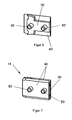
- FIG. 5 shows the design of a separating knife 40.
- FIG. 5A shows the cutting blade 40 in a side view
- FIG. 5B shows the cutting blade 40 in the front view
- FIG. 5C shows the cutting blade 40 in plan view.
- the cutting edge 41 forms with the direction of movement, which is indicated by the arrow 42, an angle ⁇ which is smaller than 90 °. This angle is preferably 75 ° to 85 °.
- the cutting edge 41 is also wedge-shaped, which is visible from FIG. 5B.
- the holes 43 are in line with the holes 33 in the doctor blade 30.
- FIG. 6 shows in perspective view the doctor blade 30 connected on one side with a cutting knife 40. The connection is made via the pins 50th
- the second separating knife 40 is also attached and held by the pins 50.
- the doctor blade 30 is arranged between the two separating blades 40.
- the design of scraper blade 30 and cutting knife 40 is made so that the cutting plane reached by the cutting blade 40 has a greater distance from the ribbon conductor 1, as the cutting plane of the Schabmessers 30. This distance is only 0.005 to 0.03 mm, but has to Result that the doctor blade 30 performs the peeling process in a clearly defined area.
- FIG. 7 shows the complete knife block 14.
Landscapes
- Engineering & Computer Science (AREA)
- Manufacturing & Machinery (AREA)
- Removal Of Insulation Or Armoring From Wires Or Cables (AREA)
Description
- In der Technik werden mehr und mehr Flachbandleiter für unterschiedliche Aufgaben eingesetzt. Ein Problem bei den Flachbandleitern ist die sogenannte Abisolierung, mit der großflächige Verbindungen zwischen dem Flachbandleiter und einem Kontakt herzustellen sind. Um Stecker oder Masseanschlüsse am Flachbandleiter anbringen zu können, muss die Isolierung rückstandslos von den Leitern entfernt werden. Diese partielle und selektive Entfernung der Isolierschicht und des Klebers von dem Leiter ist wegen der geringen Abmessungen mit höchster Präzision durchzuführen.
- Für das einseitige Abisolieren wird ein prozesskontrolliertes Fräsen benutzt, welches jedoch relativ langsam ist. Auch werden Laser eingesetzt, die eine hohe Präzision ermöglichen, jedoch ebenfalls nur mit hohem Zeitaufwand durchführbar sind. Bekannt ist auch Ultraschall einzusetzen, welches jedoch nur ein beidseitiges Abisolieren ermöglicht.
- Die Vorrichtung nach dem Oberbegriff ist aus der US-A- 4527451 bekannt. Sie dient zur Entfernung einer Isolierstoffschicht aus polymerem Werkstoff von der Oberseite mindestens eines in einem Flachbandleiter gehaltenen Signalleiters und umfasst eine Klemmeinrichtung zum unverrückbaren Andrücken des Flachbandleiters an eine im Wesentlichen eben ausgebildete Tragfläche sowie einen relativ zu dem Flachbandleiter verschiebbaren Messerblock, wobei der Messerblock parallel zu der Tragfläche verschiebar ist und wenigstens eine Schabschneide und wenigstens eine Trennschneide aufweist und wobei die Schabschneide parallel zur Tragfläche wirksam ist und die Trennschneide in einer gedachten, sich senkrecht dazu erstreckenden Schnittebene. Der Messerblock wird bei dieser Ausführung zunächst senkrecht in Richtung der Tragfläche in die Isolierstoffschicht abgesenkt und im Anschluss daran parallel zu der Tragfläche in Richtung des Endes des Flachbandleiters zurückgezogen, um die Isolierstoffschicht von dem Ende abzustreifen. Dazu is es allerdings erforderlich, zunächst einmal ein Ende an dem Flachbandleiter zu erzeugen.
- Die selektive Entfernung der Isolierstoffschicht gelingt nur ungenau. Dies liegt daran, dass sich die Isolierstoffschicht beim Eindringen des Messerblocks, das senkrecht in Richtung der Tragfläche erfolgt, elastisch verformt. Der zu entfernende Teil der Isolierstoffschicht wird dadurch ungenau begrenzt. Eine ähnliche Funktionsweise mit ähnlichen Nachteilen hat die Vorrichtung nach der DE-A-2723851.
- Aus der EP-A.0749129 ist ein speziell geformtes Flachkabel bekannt, dass mit Hilfe einer Zange abisolierbar ist, die die Isolierstoffschicht mit Messern durchtrennt, die senkrecht zur Längsrichtung des Flachkabels aufeinander zu bewegt werden.
- Der Erfindung liegt die Aufgabe zugrunde, eine neue Möglichkeit für die Abisolierung von Flachbandleitern zu schaffen, die mit einfachen Mitteln eine sehr genaue, selektive Entfernung der Isolierstoffschicht und des eingesetzten Klebers vom Signalleiter ermöglicht. Die Vorrichtung soll möglichst einfach in ihrem Aufbau und in ihrer Handhabung sein.
- Diese Aufgabe wird erfindungsgemäß dadurch gelöst, dass der Messerblock quer zur Längsrichtung des Signalleiters über den Flachbandleiter geführt ist, so wie im Anspruch 1.
- Bevorzugt werden die Schabschneiden und die Trennschneiden als gesonderte zu dem Messerblock zusammengefasste Schab- beziehungsweise Trennmesser ausgeführt. Die einzelnen Messer sind leichter herstellbar als ein kompakter Messerblock mit entsprechend geschliffenen Schneiden.
- Die Trennmesser sind mit Schnittkanten versehen, die mit der Bewegungsrichtung einen Winkel von weniger als 90° einschließen. Der Winkel beträgt bevorzugt 75° bis 85°.
- Günstig ist es, wenn das Schabmesser und / oder das Trennmesser mit keilförmig angeschärften Schnittkanten versehen sind.
- Die Vorrichtung kann so ausgeführt werden, dass der Flachbandleiter beliebig viele Signalleiter haben kann. Der Messerblock wird quer zu den Signalleitern über den Flachbandleiter geführt und die einzelnen Signalleiter von ihrer Isolierstoffschicht befreit und zwar in einer vorgegebenen Breite, welche durch die Breite des Schabmessers bestimmt ist.
- Durch die Anordnung des Schabmessers zwischen zwei Trennmessern wird eine sehr definierte Fläche an den Signalleitern abisoliert.
- Die Trennmesser und das Schabmesser sind austauschbar im Messerblock gehalten, der seinerseits Justiermittel zu definierten Festlegung in einer Werkzeugaufnahme eines Antriebmittels aufweist. Die Justiermittel können aus zwei am Messerblock vorhandenen Stiften bestehen, die sich quer zur Bewegungsrichtung erstrecken. Das Antriebsmittel selbst kann manuell oder auch motorisch betätigbar sein.
- Anhand der beiliegenden Zeichnung wird die Erfindung nachstehend näher erläutert.
- Es zeigt:
- Fig. 1 einen Flachbandleiterabschnitt mit drei Signalleitern und abisolierten Fenstern,
- Fig. 2 eine Vorrichtung in der perspektivischen Darstellung mit einem eingesetzten Messerblock,
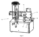
- Fig. 3 eine weitere Vorrichtung in Form einer Handzange zur Aufnahme des Messerblocks zur Abisolierung,
- Fig. 4 das Schabmesser in der Seitenansicht, Frontansicht und Draufsicht,
- Fig. 5 ein Trennmesser ebenfalls in der Seitenansicht, Frontansicht und Draufsicht,
- Fig. 6 eine perspektivische Ansicht eines Schabmessers und eines Trennmessers durch Stifte zusammengefasst und,
- Fig. 7 der Messerblock aus Schabmesser und zwei Trennmessern in der perspektivischen Darstellung.
- In der Fig. 1 ist in der perspektivischen Draufsicht ein Flachbandleiter 1 gezeigt, der aus drei Signalleitern 3 besteht, die mit einer Isolierstoffschicht 4 bedeckt sind. Der erfindungsgemäße Messerblock, der in den nachfolgenden Figuren behandelt wird, erlaubt ein Abisolieren der Isolierstoffschicht von den Signalleitern 3 an vorgegebenen Stellen, indem er quer über den Flachbandleiter 1 geführt wird. Es entstehen dann die Fenster 2, an denen die Flachbandleiter 3 von der Isolierstoffschicht und Klebstoffschicht befreit sind, so dass die Signalleiter 3 für weitere Anschlüsse zur Verfügung stehen.
- In der Fig. 2 ist eine Vorrichtung 10 gezeigt, die eine Tragfläche 11 hat, auf welcher der Flachbandleiter 1 aufliegt. Die Vorrichtung 10 ist mit einer Klemmeinrichtung 12 versehen, welche den Flachbandleiter, der hier nicht gezeigt ist, an der Tragfläche 11 andrückt und festhält. Im beweglichen Kopf 13 der Vorrichtung 10 wird der Messerblock 14 eingesetzt, der durch den Kopf 13 quer zu dem festgehaltenen Flachbandleiter 1 bewegt werden kann. Die Vorrichtung 10 ist mit Feinjustiermitteln 15 versehen, welche eine Feineinstellung des Messerblocks 14 in Bezug zum Flachbandleiter 1 ermöglichen. Außerdem hat die Vorrichtung 10 entsprechende Antriebsmotoren, welche die gewünschte Bewegung des Kopfes 13 ermöglichen.
- In der Fig. 3 ist eine mechanische Vorrichtung 20 gezeigt, die in Form einer Zange ausgebildet ist, und die allein durch das Schließen der Zange, die Klemmbewegung für den Flachbandleiter ausführt. Über eine Hebelmechanik wird nach dem Klemmen die entsprechende Bewegung des Messerblocks 14 quer zu dem in die Öffnung 21 eingeführten und in der Zeichnung nicht näher dargestellten Flachbandleiter ermöglicht. Die Tragfläche 22 stellt die ebene so Tragfläche für die Festklemmung des Flachbandleiters dar. Die Justiermittel 15 für die Feineinstellung des Abstands des Messerblocks 14 vom Flachbandleiter 1 sind auf der oberen Hälfte der Flachzange 20 angebracht.
- In der Fig. 4 ist das Schabmesser 30 dargestellt und zwar zeigt Fig. 4 A das 5 Schabmesser 30 in der Seitenansicht, die Fig. 4 B das Schabmesser 30 in der Frontansicht und Fig. 4 C das Schabmesser 30 in der Draufsicht. Das Schabmesser 30 hat zwei Schneidkanten 31, die keilförmig ausgebildet sind. Dabei ist der Winkel α, der quer zur Schneidrichtung liegt, größer als der Winkel β, welcher längs zur Schnittrichtung verläuft. Außerdem sind die 10 Schnittkanten 31 mit einer leichten Phase 32 versehen. Die beiden Bohrungen 33 sind für die Aufnahme der Stifte für das Zusammenfügen des Schabmessers 30 mit den seitlich angebrachten Trennmessern 40 und das Einsetzen des fertigen Messerblocks 14 in die dafür vorgesehene Vorrichtung 10 beziehungsweise 20 angebracht.
- Die Fig. 5 zeigt die Ausbildung eines Trennmessers 40. Dabei zeigt die Fig. 5 A das Trennmesser 40 in der Seitenansicht, die Fig. 5 B das Trennmesser 40 in der Frontansicht und Fig. 5 C das Trennmesser 40 in der Draufsicht. Die Schnittkante 41 bildet mit der Bewegungsrichtung, die durch den Pfeil 42 angezeigt ist, einen Winkel δ, der kleiner ist als 90°. Bevorzugt beträgt dieser Winkel 75° bis 85°. Die Schnittkante 41 ist ebenfalls keilförmig ausgebildet, was aus der Fig. 5 B sichtbar wird. Die Bohrungen 43 stimmen mit den Bohrungen 33 im Schabmesser 30 überein.
- Die Fig. 6 zeigt in der perspektivischen Ansicht das Schabmesser 30 verbunden an der einen Seite mit einem Trennmesser 40. Die Verbindung erfolgt über die Stifte 50.
- In der Fig. 7 ist auch das zweite Trennmesser 40 angefügt und von den Stiften so 50 gehalten. Das Schabmesser 30 ist zwischen den beiden Trennmessern 40 angeordnet. Dabei ist die Ausgestaltung von Schabmesser 30 und Trennmesser 40 so vorgenommen, dass die vom Trennmesser 40 erreichte Schnittebene einen größeren Abstand von dem Flachbandleiter 1 hat, als die Schnittebene des Schabmessers 30. Dieser Abstand beträgt lediglich 0,005 bis 0,03 mm, hat aber zur Folge, dass das Schabmesser 30 in einem eindeutig abgegrenzten Bereich den Schälvorgang vornimmt. Die Fig. 7 zeigt den vollständigen Messerblock 14.
Claims (10)
- Vorrichtung (10, 20) zur Entfernung einer Isolierstoffschicht (4) aus polymerem Werkstoff von der Oberseite mindestens eines in einem Flachbandleiter (1) gehaltenen Signalleiters (3), umfassend eine Klemmeinrichtung (12) zum unverrückbaren Andrücken des Flachbandleiters (1) an eine im Wesentlichen eben ausgebildete Tragfläche (11) sowie einen quer zu dem Flachbandleiter (1) und parallel zu der Tragfläche (11) verschiebbaren Messerblock (14), der wenigstens eine Schabschneide (31) sowie wenigstens eine Trennschneide (41) aufweist, wobei die Schabschneide (31) parallel zur Tragfläche (11) angeordnet ist, dadurch gekennzeichnet, dass die Trennschneide (41) senkrecht zu der Tragfläche (11) und zugleich quer zu dem Signaleiter (3) angeordnet ist und dass der Messerblock (14) zum Ausschälen eines Fensters (2) aus der Isolierstoffschicht nur zugleich quer zu den Signalleitern (3) und parallel zu der Tragfläche (11) über den Flachbandleiter (1) führbar ist.
- Vorrichtung nach Anspruch 1, dadurch gekennzeichnet, dass die Schabschneide (31) und die Trennschneide (41) Bestandteile von gesonderten, zu dem Messerblock (14) zusammengefassten Schabbeziehungsweise Trennmessern (30, 40) sind.
- Vorrichtung nach Anspruch 2, dadurch gekennzeichnet, dass das Trennmesser (40) eine Trennschneide (41) aufweist, die mit seiner Bewegungsrichtung (42) einen Winkel δ von weniger als 90° einschließt.
- Vorrichtung nach Anspruch 3, dadurch gekennzeichnet, dass der Winkel δ 75° bis 85° beträgt.
- Vorrichtung nach einem der Ansprüche 2 bis 4, dadurch gekennzeichnet, dass das Schabmesser (30) und / oder das Trennmesser (40) eine keilförmig angeschärfte Schnittkante (31) haben.
- Vorrichtung nach einem der Ansprüche 2 bis 5, dadurch gekennzeichnet, dass das Trennmesser (40) einen größeren Abstand von der Tragfläche (11) hat als das Schabmesser (30).
- Vorrichtung nach einem der Ansprüche 2 bis 6, dadurch gekennzeichnet, dass das Schabmesser (30) zwischen zwei Trennmessern (40) angeordnet ist.
- Vorrichtung nach einem der Ansprüche 2 bis 7, dadurch gekennzeichnet, dass die Trennmesser (40) und das Schabmesser (30) austauschbar im Messerblock (14) gehalten sind.
- Vorrichtung nach einem der Ansprüche 1 bis 8, dadurch gekennzeichnet, dass die Vorrichtung (10) Justiermittel (15) zur definierten Festlegung des Messerblocks (14) in einer Werkzeugaufnahme eines Antriebmittels aufweist.
- Vorrichtung nach einem der Ansprüche 1 bis 9, dadurch gekennzeichnet, dass der Messerblock (14) zumindest zwei Stifte (50) hat, die sich quer zur Bewegungsrichtung erstrecken.
Applications Claiming Priority (2)
| Application Number | Priority Date | Filing Date | Title |
|---|---|---|---|
| DE10145009A DE10145009C1 (de) | 2001-09-12 | 2001-09-12 | Vorrichtung zur Entfernung einer Isolierstoffschicht von einem Flachbandleiter |
| DE10145009 | 2001-09-12 |
Publications (3)
| Publication Number | Publication Date |
|---|---|
| EP1294062A2 EP1294062A2 (de) | 2003-03-19 |
| EP1294062A3 EP1294062A3 (de) | 2005-07-20 |
| EP1294062B1 true EP1294062B1 (de) | 2006-10-11 |
Family
ID=7698826
Family Applications (1)
| Application Number | Title | Priority Date | Filing Date |
|---|---|---|---|
| EP02007959A Expired - Lifetime EP1294062B1 (de) | 2001-09-12 | 2002-04-10 | Vorrichtung zur Entfernung einer Isolierstoffschicht von einem Flachbandleiter |
Country Status (3)
| Country | Link |
|---|---|
| EP (1) | EP1294062B1 (de) |
| AT (1) | ATE342594T1 (de) |
| DE (2) | DE10145009C1 (de) |
Families Citing this family (3)
| Publication number | Priority date | Publication date | Assignee | Title |
|---|---|---|---|---|
| DE202006002004U1 (de) * | 2006-02-07 | 2007-06-21 | Weidmüller Interface GmbH & Co. KG | Abmantelwerkzeug |
| CN104953513A (zh) * | 2015-06-11 | 2015-09-30 | 苏州爱吉亚电子科技有限公司 | 高精度的极细线加工设备 |
| CN104953443A (zh) * | 2015-06-11 | 2015-09-30 | 苏州爱吉亚电子科技有限公司 | 手工剥线机 |
Family Cites Families (5)
| Publication number | Priority date | Publication date | Assignee | Title |
|---|---|---|---|---|
| DE2723851C2 (de) * | 1977-05-26 | 1984-02-09 | kabelmetal electro GmbH, 3000 Hannover | Verfahren zum Abisolieren der Enden einer Flachleiter-Bandleitung |
| US4527451A (en) * | 1984-05-29 | 1985-07-09 | Amp Incorporated | Stripping tool for shielded ribbon cable |
| DE4007762A1 (de) * | 1990-03-12 | 1991-09-19 | Kabelmetal Electro Gmbh | Verfahren und vorrichtung zum entfernen einer kunststoffschicht von lwl-bandleitungen |
| FR2735604B1 (fr) * | 1995-06-14 | 1997-07-18 | Schneider Electric Sa | Cable plat et pince a denuder |
| EP1124297B1 (de) * | 2000-02-11 | 2006-05-24 | Komax Holding Ag | Verfahren und Einrichtung zur Abisolierung eines Flachkabels |
-
2001
- 2001-09-12 DE DE10145009A patent/DE10145009C1/de not_active Expired - Lifetime
-
2002
- 2002-04-10 AT AT02007959T patent/ATE342594T1/de not_active IP Right Cessation
- 2002-04-10 DE DE50208394T patent/DE50208394D1/de not_active Expired - Lifetime
- 2002-04-10 EP EP02007959A patent/EP1294062B1/de not_active Expired - Lifetime
Also Published As
| Publication number | Publication date |
|---|---|
| DE10145009C1 (de) | 2003-04-03 |
| EP1294062A3 (de) | 2005-07-20 |
| EP1294062A2 (de) | 2003-03-19 |
| ATE342594T1 (de) | 2006-11-15 |
| DE50208394D1 (de) | 2006-11-23 |
Similar Documents
| Publication | Publication Date | Title |
|---|---|---|
| DE2838459A1 (de) | Vorrichtung fuer tragbare motorkraftsaegen | |
| DE3312233C1 (de) | Stanzmaschine und Ausklinkmaschine | |
| DE2714468C2 (de) | Metallstreifen mit voneinander beabstandeten Klingen zur Herstellung chirurgischer Klingen und Verfahren zur Aufbereitung | |
| EP1294062B1 (de) | Vorrichtung zur Entfernung einer Isolierstoffschicht von einem Flachbandleiter | |
| DE19929583B4 (de) | Vorrichtung und Verfahren zur Vorbereitung plattenartigen Materials für abgewinkelte Verschalungen | |
| DE10029195C1 (de) | Vorrichtung und Verfahren zum Durchtrennen von stabförmigen Werkstücken | |
| EP0145049B1 (de) | Abisoliervorrichtung, insbesondere für Leiter mit zäher Isolationsschicht | |
| DE4029582A1 (de) | Maschine fuer die kontaktierung einer elektrotechnischen verbindungsvorrichtung | |
| EP0222112B1 (de) | Vorrichtung zum Abisolieren von Kabeln | |
| DE3406813C2 (de) | ||
| DE3933316A1 (de) | Verfahren und vorrichtung zum verbinden eines elektrischen steckverbinders mit einem kabel | |
| DE20003820U1 (de) | Brechvorrichtung für Fliesen | |
| DE69007480T2 (de) | Verfahren zur herstellung eines glasmessers. | |
| DE10323495B3 (de) | Verfahren und Vorrichtung zum Abisolieren von Flachbandleitern | |
| DE202006007771U1 (de) | Vorrichtung zur Bearbeitung von plattenförmigen Bauteilen wie keramischen Fliesen u.dgl. | |
| DE3013608A1 (de) | Vorrichtung zum zurichten der kopfenden von koaxialkabeln | |
| DE602005001516T2 (de) | Schneidvorrichtung zum Schneiden von Metallen, besonders zum Schneiden von Metallprofilen | |
| DE3738419A1 (de) | Schneidwerkzeug zum entfernen von kabelmaentel, insbesondere von glasfaserkabeln | |
| DE1577996C3 (de) | Vorrichtung zum Einklemmen von Keramikfliesen auf einer Bohrmaschine | |
| DE2316102A1 (de) | Schaelwerkzeug fuer kunststoffisolierte elektrische kabel | |
| DE8308645U1 (de) | Abmantelungswerkzeug | |
| DE1577996B2 (de) | Vorrichtung zum einklemmen von keramikfliesen auf einer bohrmaschine | |
| DE2044036A1 (de) | Vorrichtung zur Schaffung einer Öffnung in einem Überzug eines mit Metall überzöge nen Kabels | |
| DE3433381A1 (de) | Vorrichtung zum lochen von schleifmitteltraegern fuer elektromotorisch angetriebene handschwingschleifer | |
| EP3124191A1 (de) | Bearbeitungsaggregat für die bearbeitung von plattenförmigen werkstücken und verfahren zum bearbeiten eines plattenförmigen werkstücks |
Legal Events
| Date | Code | Title | Description |
|---|---|---|---|
| PUAI | Public reference made under article 153(3) epc to a published international application that has entered the european phase |
Free format text: ORIGINAL CODE: 0009012 |
|
| AK | Designated contracting states |
Kind code of ref document: A2 Designated state(s): AT BE CH CY DE DK ES FI FR GB GR IE IT LI LU MC NL PT SE TR Designated state(s): AT BE CH CY DE DK ES FI FR GB GR IE IT LI LU MC NL PT SE TR |
|
| AX | Request for extension of the european patent |
Extension state: AL LT LV MK RO SI |
|
| PUAL | Search report despatched |
Free format text: ORIGINAL CODE: 0009013 |
|
| AK | Designated contracting states |
Kind code of ref document: A3 Designated state(s): AT BE CH CY DE DK ES FI FR GB GR IE IT LI LU MC NL PT SE TR |
|
| AX | Request for extension of the european patent |
Extension state: AL LT LV MK RO SI |
|
| RIC1 | Information provided on ipc code assigned before grant |
Ipc: 7H 02G 1/12 B Ipc: 7H 01R 43/28 A |
|
| 17P | Request for examination filed |
Effective date: 20050614 |
|
| AKX | Designation fees paid |
Designated state(s): AT BE CH CY DE DK ES FI FR GB GR IE IT LI LU MC NL PT SE TR |
|
| GRAP | Despatch of communication of intention to grant a patent |
Free format text: ORIGINAL CODE: EPIDOSNIGR1 |
|
| GRAS | Grant fee paid |
Free format text: ORIGINAL CODE: EPIDOSNIGR3 |
|
| GRAA | (expected) grant |
Free format text: ORIGINAL CODE: 0009210 |
|
| RTI1 | Title (correction) |
Free format text: DEVICE FOR REMOVING AN INSULANT LAYER FROM A RIBBON CONDUCTOR |
|
| AK | Designated contracting states |
Kind code of ref document: B1 Designated state(s): AT BE CH CY DE DK ES FI FR GB GR IE IT LI LU MC NL PT SE TR |
|
| PG25 | Lapsed in a contracting state [announced via postgrant information from national office to epo] |
Ref country code: FI Free format text: LAPSE BECAUSE OF FAILURE TO SUBMIT A TRANSLATION OF THE DESCRIPTION OR TO PAY THE FEE WITHIN THE PRESCRIBED TIME-LIMIT Effective date: 20061011 Ref country code: IE Free format text: LAPSE BECAUSE OF FAILURE TO SUBMIT A TRANSLATION OF THE DESCRIPTION OR TO PAY THE FEE WITHIN THE PRESCRIBED TIME-LIMIT Effective date: 20061011 Ref country code: NL Free format text: LAPSE BECAUSE OF FAILURE TO SUBMIT A TRANSLATION OF THE DESCRIPTION OR TO PAY THE FEE WITHIN THE PRESCRIBED TIME-LIMIT Effective date: 20061011 |
|
| REG | Reference to a national code |
Ref country code: GB Ref legal event code: FG4D Free format text: NOT ENGLISH |
|
| REG | Reference to a national code |
Ref country code: CH Ref legal event code: EP |
|
| REG | Reference to a national code |
Ref country code: IE Ref legal event code: FG4D Free format text: LANGUAGE OF EP DOCUMENT: GERMAN |
|
| REF | Corresponds to: |
Ref document number: 50208394 Country of ref document: DE Date of ref document: 20061123 Kind code of ref document: P |
|
| GBT | Gb: translation of ep patent filed (gb section 77(6)(a)/1977) |
Effective date: 20061207 |
|
| PG25 | Lapsed in a contracting state [announced via postgrant information from national office to epo] |
Ref country code: SE Free format text: LAPSE BECAUSE OF FAILURE TO SUBMIT A TRANSLATION OF THE DESCRIPTION OR TO PAY THE FEE WITHIN THE PRESCRIBED TIME-LIMIT Effective date: 20070111 Ref country code: DK Free format text: LAPSE BECAUSE OF FAILURE TO SUBMIT A TRANSLATION OF THE DESCRIPTION OR TO PAY THE FEE WITHIN THE PRESCRIBED TIME-LIMIT Effective date: 20070111 |
|
| REG | Reference to a national code |
Ref country code: CH Ref legal event code: NV Representative=s name: SCHNEIDER FELDMANN AG PATENT- UND MARKENANWAELTE |
|
| PG25 | Lapsed in a contracting state [announced via postgrant information from national office to epo] |
Ref country code: ES Free format text: LAPSE BECAUSE OF FAILURE TO SUBMIT A TRANSLATION OF THE DESCRIPTION OR TO PAY THE FEE WITHIN THE PRESCRIBED TIME-LIMIT Effective date: 20070122 |
|
| PG25 | Lapsed in a contracting state [announced via postgrant information from national office to epo] |
Ref country code: PT Free format text: LAPSE BECAUSE OF FAILURE TO SUBMIT A TRANSLATION OF THE DESCRIPTION OR TO PAY THE FEE WITHIN THE PRESCRIBED TIME-LIMIT Effective date: 20070319 |
|
| NLV1 | Nl: lapsed or annulled due to failure to fulfill the requirements of art. 29p and 29m of the patents act | ||
| ET | Fr: translation filed | ||
| REG | Reference to a national code |
Ref country code: IE Ref legal event code: FD4D |
|
| PLBE | No opposition filed within time limit |
Free format text: ORIGINAL CODE: 0009261 |
|
| STAA | Information on the status of an ep patent application or granted ep patent |
Free format text: STATUS: NO OPPOSITION FILED WITHIN TIME LIMIT |
|
| 26N | No opposition filed |
Effective date: 20070712 |
|
| BERE | Be: lapsed |
Owner name: BERNHARD SCHAFER WERKZEUG- U. SONDERMASCHINEN G.M Effective date: 20070430 |
|
| PG25 | Lapsed in a contracting state [announced via postgrant information from national office to epo] |
Ref country code: BE Free format text: LAPSE BECAUSE OF NON-PAYMENT OF DUE FEES Effective date: 20070430 |
|
| PG25 | Lapsed in a contracting state [announced via postgrant information from national office to epo] |
Ref country code: GR Free format text: LAPSE BECAUSE OF FAILURE TO SUBMIT A TRANSLATION OF THE DESCRIPTION OR TO PAY THE FEE WITHIN THE PRESCRIBED TIME-LIMIT Effective date: 20070112 |
|
| PG25 | Lapsed in a contracting state [announced via postgrant information from national office to epo] |
Ref country code: AT Free format text: LAPSE BECAUSE OF NON-PAYMENT OF DUE FEES Effective date: 20070410 |
|
| PG25 | Lapsed in a contracting state [announced via postgrant information from national office to epo] |
Ref country code: MC Free format text: LAPSE BECAUSE OF NON-PAYMENT OF DUE FEES Effective date: 20070430 |
|
| PG25 | Lapsed in a contracting state [announced via postgrant information from national office to epo] |
Ref country code: CY Free format text: LAPSE BECAUSE OF FAILURE TO SUBMIT A TRANSLATION OF THE DESCRIPTION OR TO PAY THE FEE WITHIN THE PRESCRIBED TIME-LIMIT Effective date: 20061011 Ref country code: LU Free format text: LAPSE BECAUSE OF NON-PAYMENT OF DUE FEES Effective date: 20070410 |
|
| PG25 | Lapsed in a contracting state [announced via postgrant information from national office to epo] |
Ref country code: TR Free format text: LAPSE BECAUSE OF FAILURE TO SUBMIT A TRANSLATION OF THE DESCRIPTION OR TO PAY THE FEE WITHIN THE PRESCRIBED TIME-LIMIT Effective date: 20061011 |
|
| REG | Reference to a national code |
Ref country code: FR Ref legal event code: PLFP Year of fee payment: 15 |
|
| REG | Reference to a national code |
Ref country code: FR Ref legal event code: PLFP Year of fee payment: 16 |
|
| REG | Reference to a national code |
Ref country code: FR Ref legal event code: PLFP Year of fee payment: 17 |
|
| PGFP | Annual fee paid to national office [announced via postgrant information from national office to epo] |
Ref country code: GB Payment date: 20190322 Year of fee payment: 18 |
|
| REG | Reference to a national code |
Ref country code: CH Ref legal event code: PFA Owner name: BERNHARD SCHAEFER WERKZEUG- U. SONDERMASCHINEN, DE Free format text: FORMER OWNER: BERNHARD SCHAEFER WERKZEUG- U. SONDERMASCHINEN GMBH, DE |
|
| GBPC | Gb: european patent ceased through non-payment of renewal fee |
Effective date: 20200410 |
|
| PG25 | Lapsed in a contracting state [announced via postgrant information from national office to epo] |
Ref country code: GB Free format text: LAPSE BECAUSE OF NON-PAYMENT OF DUE FEES Effective date: 20200410 |
|
| PGFP | Annual fee paid to national office [announced via postgrant information from national office to epo] |
Ref country code: DE Payment date: 20210427 Year of fee payment: 20 Ref country code: FR Payment date: 20210427 Year of fee payment: 20 Ref country code: IT Payment date: 20210429 Year of fee payment: 20 |
|
| PGFP | Annual fee paid to national office [announced via postgrant information from national office to epo] |
Ref country code: CH Payment date: 20210423 Year of fee payment: 20 |
|
| REG | Reference to a national code |
Ref country code: DE Ref legal event code: R071 Ref document number: 50208394 Country of ref document: DE |
|
| REG | Reference to a national code |
Ref country code: CH Ref legal event code: PL |