EP1293619B1 - Trägerstruktur und Trägerverbindung - Google Patents
Trägerstruktur und Trägerverbindung Download PDFInfo
- Publication number
- EP1293619B1 EP1293619B1 EP02394092A EP02394092A EP1293619B1 EP 1293619 B1 EP1293619 B1 EP 1293619B1 EP 02394092 A EP02394092 A EP 02394092A EP 02394092 A EP02394092 A EP 02394092A EP 1293619 B1 EP1293619 B1 EP 1293619B1
- Authority
- EP
- European Patent Office
- Prior art keywords
- connector
- arms
- truss
- rafter
- truss system
- Prior art date
- Legal status (The legal status is an assumption and is not a legal conclusion. Google has not performed a legal analysis and makes no representation as to the accuracy of the status listed.)
- Expired - Lifetime
Links
- 239000010960 cold rolled steel Substances 0.000 abstract description 2
- 238000006243 chemical reaction Methods 0.000 description 2
- 238000005253 cladding Methods 0.000 description 1
- 238000010276 construction Methods 0.000 description 1
Images


Classifications
-
- E—FIXED CONSTRUCTIONS
- E04—BUILDING
- E04C—STRUCTURAL ELEMENTS; BUILDING MATERIALS
- E04C3/00—Structural elongated elements designed for load-supporting
- E04C3/02—Joists; Girders, trusses, or trusslike structures, e.g. prefabricated; Lintels; Transoms; Braces
- E04C3/04—Joists; Girders, trusses, or trusslike structures, e.g. prefabricated; Lintels; Transoms; Braces of metal
- E04C3/11—Joists; Girders, trusses, or trusslike structures, e.g. prefabricated; Lintels; Transoms; Braces of metal with non-parallel upper and lower edges, e.g. roof trusses
-
- E—FIXED CONSTRUCTIONS
- E04—BUILDING
- E04B—GENERAL BUILDING CONSTRUCTIONS; WALLS, e.g. PARTITIONS; ROOFS; FLOORS; CEILINGS; INSULATION OR OTHER PROTECTION OF BUILDINGS
- E04B1/00—Constructions in general; Structures which are not restricted either to walls, e.g. partitions, or floors or ceilings or roofs
- E04B1/18—Structures comprising elongated load-supporting parts, e.g. columns, girders, skeletons
- E04B1/24—Structures comprising elongated load-supporting parts, e.g. columns, girders, skeletons the supporting parts consisting of metal
- E04B1/2403—Connection details of the elongated load-supporting parts
- E04B2001/2415—Brackets, gussets, joining plates
-
- E—FIXED CONSTRUCTIONS
- E04—BUILDING
- E04B—GENERAL BUILDING CONSTRUCTIONS; WALLS, e.g. PARTITIONS; ROOFS; FLOORS; CEILINGS; INSULATION OR OTHER PROTECTION OF BUILDINGS
- E04B1/00—Constructions in general; Structures which are not restricted either to walls, e.g. partitions, or floors or ceilings or roofs
- E04B1/18—Structures comprising elongated load-supporting parts, e.g. columns, girders, skeletons
- E04B1/24—Structures comprising elongated load-supporting parts, e.g. columns, girders, skeletons the supporting parts consisting of metal
- E04B1/2403—Connection details of the elongated load-supporting parts
- E04B2001/2421—Socket type connectors
-
- E—FIXED CONSTRUCTIONS
- E04—BUILDING
- E04B—GENERAL BUILDING CONSTRUCTIONS; WALLS, e.g. PARTITIONS; ROOFS; FLOORS; CEILINGS; INSULATION OR OTHER PROTECTION OF BUILDINGS
- E04B1/00—Constructions in general; Structures which are not restricted either to walls, e.g. partitions, or floors or ceilings or roofs
- E04B1/18—Structures comprising elongated load-supporting parts, e.g. columns, girders, skeletons
- E04B1/24—Structures comprising elongated load-supporting parts, e.g. columns, girders, skeletons the supporting parts consisting of metal
- E04B1/2403—Connection details of the elongated load-supporting parts
- E04B2001/2448—Connections between open section profiles
-
- E—FIXED CONSTRUCTIONS
- E04—BUILDING
- E04B—GENERAL BUILDING CONSTRUCTIONS; WALLS, e.g. PARTITIONS; ROOFS; FLOORS; CEILINGS; INSULATION OR OTHER PROTECTION OF BUILDINGS
- E04B1/00—Constructions in general; Structures which are not restricted either to walls, e.g. partitions, or floors or ceilings or roofs
- E04B1/18—Structures comprising elongated load-supporting parts, e.g. columns, girders, skeletons
- E04B1/24—Structures comprising elongated load-supporting parts, e.g. columns, girders, skeletons the supporting parts consisting of metal
- E04B2001/2466—Details of the elongated load-supporting parts
- E04B2001/2469—Profile with an array of connection holes
-
- E—FIXED CONSTRUCTIONS
- E04—BUILDING
- E04B—GENERAL BUILDING CONSTRUCTIONS; WALLS, e.g. PARTITIONS; ROOFS; FLOORS; CEILINGS; INSULATION OR OTHER PROTECTION OF BUILDINGS
- E04B1/00—Constructions in general; Structures which are not restricted either to walls, e.g. partitions, or floors or ceilings or roofs
- E04B1/38—Connections for building structures in general
- E04B1/58—Connections for building structures in general of bar-shaped building elements
- E04B2001/5868—Hinged connections
-
- E—FIXED CONSTRUCTIONS
- E04—BUILDING
- E04C—STRUCTURAL ELEMENTS; BUILDING MATERIALS
- E04C3/00—Structural elongated elements designed for load-supporting
- E04C3/02—Joists; Girders, trusses, or trusslike structures, e.g. prefabricated; Lintels; Transoms; Braces
- E04C3/04—Joists; Girders, trusses, or trusslike structures, e.g. prefabricated; Lintels; Transoms; Braces of metal
- E04C2003/0486—Truss like structures composed of separate truss elements
- E04C2003/0491—Truss like structures composed of separate truss elements the truss elements being located in one single surface or in several parallel surfaces
Definitions
- the invention relates to truss systems and in particular to a truss system for use in converting a flat to a pitched roof.
- the invention relates to a truss system connector of the type comprising a sleeve portion to receive a structural member and a pair of arms extending from the sleeve portion.
- WO 01/14658 A describes a connector according to the preamble of claim 1.
- a truss system connector comprising a sleeve portion to receive a structural member and a pair of arms extending from the sleeve portion to receive another structural member therebetween, said arms of the connector being cranked outwardly, characterised in that each of said arms has only one hole and said holes are aligned for receiving a pin.
- the sleeve portion of the connector is of channel section comprising a bottom and a pair of upstanding sides, the arms extending from the sides of the channel section.
- the invention also provides a truss system comprising a bottom boom, a rafter, at least one web member for extending between the boom and the rafter, and a truss connector of the invention.
- the sleeve of the truss connector receives a web member and the arms of the truss connector are pin jointed to the rafter or the bottom boom.
- the truss system in addition comprises a second connector of the type comprising a sleeve portion to receive a structural member and a pair of arms extending from the sleeve wherein the arms of the second connector are co-planar with the sleeve portion.
- the sleeve of second truss connector may receive a web member and the arms of the second connector are pin jointed to the rafter or the bottom boom.
- the bottom boom and/or the rafter comprises a number of pre-drilled holes for receiving a pin for mounting a connector to a bottom boom or rafter.
- the bottom boom and/or rafter and/or web is a lipped channel.
- bottom boom and the rafter are of the same section.
- the bottom boom, the rafter and the web member are of the same section.
- the connector of Fig. 4 and 5 can be a part of the truss system of the invention as defined in claims 3 to 11.
- the connector of Fig. 4 and 5 as such does however not fall within the scope of the connector of the invention as defined in claims 1 and 2.
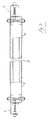
- a truss system comprising bottom booms 1, rafters 2, and a plurality of web members 3 extending between the bottom booms 1 and the rafters 2.
- Connectors 5 are used for pin jointing between the web members 3, the rafters 2 and the bottom booms 1.
- Each of the rafters 2, bottom booms 1 and web members 3 are in this case of the same lipped channel section 10 (Fig. 8) of cold rolled steel.
- the arms 11 of the channel section 10 are pre-drilled with a number of spaced apart holes 12, the holes 12 in the opposite arms 11 of the channel being aligned to receive a mounting pin 13. Because the rafters, bottom booms and web members are of the same section the truss system is greatly simplified as the number of different elements is minimised.
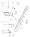
- the system comprises two different connectors, namely a straight knuckle connector 5a (Figs 4 and 5) and a cranked knuckle connector 5b (Figs 6 and 7).
- the connector comprises a sleeve portion 20 to telescopically receive a section 10 such as a web member 3 and at least one arm extending from the sleeve portion 20 for pin jointing, for example to a bottom boom 1 or a rafter 2.
- the sleeve portion 20 has lipped channel cross section for receiving the lipped channel section of the web member 3.
- For secure mounting preferably there are two arms 21, 22 extending from the sides of the sleeve portion 20 and the arms 21, 22 are spaced-apart to defined a gap therebetween.
- the arms 21, 22 are co-planner with the sleeve portion 20 and the gap between the arms 21, 22 is approximately the same as or slightly greater than the width of the channel section 10 so that the arms 21, 22 embrace the channel section 10 and are securely pin jointed to it.
- the arms 21, 22 are cranked outwardly at 23 so that the gap defined between them is wider than the gap between the arms of the connector 5a to embrace not only a channel section 10 but also to receive the arms of a connector 5a therebetween, on assembly as illustrated particularly in Fig. 2.
- the arms 21, 22 of both connectors 5a, 5b have pre-drilled holes 25 adjacent the free ends thereof for alignment, on assembly, with the holes 12 of the channel section 10.
- a pin 13 in the form of a bolt is passed through the holes in the connectors 5a, 5b and the channel section 10 which is used for the bottom booms 1, rafters 2 and web members 3.
- the system can be used for any desired angle of web 3 between a bottom boom 1 and a rafter 2.
- the connectors 5a and/or 5b form a pin joint at the attachment between a web member 3 and a bottom boom 1 or a rafter 2 as will be particularly apparent from Fig 2.
- a typical roof structure built up from the truss system of the invention is illustrated in Fig 1. Even with such a relatively simple structure the variations in the web angles will be apparent. Using the truss system of the invention a wide variation in web angles can be catered for using the same components.
- FIGs 9 to 12 Various roof details that are formed using the truss system of the invention are illustrated in Figs 9 to 12.
- Fig 9 illustrates an apex detail in which connectors 5 are used to pin joint rafters 2 at the apex.
- a top tie 30 extends between the rafters 2 and the ends of the adjacent web members 3 as extended by the connectors 5.
- Fig 10 illustrates an eaves detail for parapet fixing in which a bottom boom 1 is secured directly to an existing roof for conversion of a flat roof to a pitched roof.
- FIG. 11 An eaves detail for a roof fixing is illustrated in Fig. 11.
- a holding down cleat 35 is stitched to the side of the bottom boom 1.
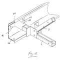
- FIG. 12 An eaves detail including soffit and facia supports is illustrated in Fig 12.
- a bottom boom 1 is attached to an eaves beam 40 using a connector 45.
- the connector 45 has a sleeve 46 to receive the bottom boom 1 and outturned arms 47, 48 which are bolted to the eaves beam.
- a clear 49 is also provided.
- the pin jointed truss system of the invention is lightweight and provides a cost effective flat to pitched roof conversion system particularly in clear span (unsupported) applications of up to 12 metres or for larger spans in which support can be provided by the existing roof.
- the truss system is versatile and can be used in conjunction with any suitable cladding system.
- the components of the truss system are pre-fabricated and standardised for quick and simple assembly. The components are lightweight and can be readily assembled on a roof or on the ground and easily handled into position is avoided for clear span systems. Disruption to a building or its occupants.
Landscapes
- Engineering & Computer Science (AREA)
- Architecture (AREA)
- Civil Engineering (AREA)
- Structural Engineering (AREA)
- Joining Of Building Structures In Genera (AREA)
- Rod-Shaped Construction Members (AREA)
- Wire Bonding (AREA)
- Led Device Packages (AREA)
- Non-Reversible Transmitting Devices (AREA)
Claims (11)
- Fachwerksystemverbinder (5b), der einen Hülsenteil (20) zum Aufnehmen eines Konstruktionselements (1, 2, 3) und ein Paar.von Armen (21, 22) aufweist, die sich von dem Hülsenteil (20) zum Aufnehmen eines andere Konstruktionselements zwischen denselben erstrecken; wobei die genannten Arme (21, 22) des Verbinders nach außen verkröpft sind, dadurch gekennzeichnet, dass jeder der genannten Arme (21, 22) nur ein Loch (25) aufweist und die genannten Löcher (25) zum Aufnehmen eines Bolzens (13) ausgerichtet sind.
- Verbinder nach Anspruch 1, bei dem der Hülsenteil (20) des Verbinders (5b) einen Kanalschnitt aufweist, der einen Boden und ein Paar hochstehender Seiten aufweist, wobei die Arme (21, 22) sich von den Seiten des Kanalschnitts erstrecken.
- Fachwerksystem, das einen Untergurt (1), einen Sparren (2), mindestens ein Stegelement (3), das zwischen dem Gurt (1) und dem Sparren (2) verlaufen soll, und einen Fachwerkverbinder (5b) gemäß Anspruch 1 oder 2 aufweist, wobei die Hülse (20) des Fachwerkverbinders (5b) ein Stegelement (3) aufnimmt und die Arme (21, 22) des Fachwerkverbinders (5b) durch Bolzen mit dem Sparren (2) oder dem Untergurt ( 1 ) verbunden werden.
- Fachwerksystem nach Anspruch 3, das einen zweiten Verbinder (5(a)) des Typs aufweist, der einen Hülsenteil (20) zum Aufnehmen eines Konstruktionselements (1, 2, 3) und ein Paar von Armen (21, 22) umfasst, die sich von der Hülse erstrecken, wobei die Arme (21, 22) des zweiten Verbinders (5(a)) koplanar mit dem Hülsenteil sind.
- Fachwerksystem nach Anspruch 4, bei dem die Hülse (20) des zweiten Fachwerkverbinders (5(a)) ein Stegelement (3) aufnimmt, und die Arme (21, 22) des zweiten Verbinders (5(a)) durch Bolzen mit dem Sparren (2) oder dem Untergurt (1) verbunden werden.
- Fachwerksystem nach einem der Ansprüche 3 bis 5, bei dem der Untergurt (1) und/oder der Sparren (2) eine Anzahl vorgebohrter Löcher (12) zum Aufnehmen des Bolzens (13) aufweist, um einen Verbinder (5, 5a, 5b) an einem Untergurt (1) oder Sparren (2) anzubringen.
- Fachwerksystem nach einem der Ansprüche 3 bis 6, bei dem der Untergurt (1) ein mit einem Rand versehener Kanal ist.
- Fachwerksystem nach einem der Ansprüche 3 bis 7, bei dem der Sparren (2) ein mit einem Rand versehener Kanal ist.
- Fachwerksystem nach einem der Ansprüche 3 bis 8, bei dem das Stegelement (3) ein mit einem Rand versehener Kanal ist.
- Fachwerksystem nach einem der Ansprüche 3 bis 9, bei dem der Untergurt (1) und der Sparren (2) den gleichen Schnitt aufweisen.
- Fachwerksystem nach einem der Ansprüche 3 bis 10, bei dem der Untergurt (1), der Sparren (2) und das Stegelement (3) den gleichen Schnitt aufweisen.
Priority Applications (1)
| Application Number | Priority Date | Filing Date | Title |
|---|---|---|---|
| EP02394092A EP1293619B1 (de) | 2001-09-12 | 2002-09-12 | Trägerstruktur und Trägerverbindung |
Applications Claiming Priority (3)
| Application Number | Priority Date | Filing Date | Title |
|---|---|---|---|
| EP01650103 | 2001-09-12 | ||
| EP01650103 | 2001-09-12 | ||
| EP02394092A EP1293619B1 (de) | 2001-09-12 | 2002-09-12 | Trägerstruktur und Trägerverbindung |
Publications (2)
| Publication Number | Publication Date |
|---|---|
| EP1293619A1 EP1293619A1 (de) | 2003-03-19 |
| EP1293619B1 true EP1293619B1 (de) | 2005-02-09 |
Family
ID=8183605
Family Applications (1)
| Application Number | Title | Priority Date | Filing Date |
|---|---|---|---|
| EP02394092A Expired - Lifetime EP1293619B1 (de) | 2001-09-12 | 2002-09-12 | Trägerstruktur und Trägerverbindung |
Country Status (5)
| Country | Link |
|---|---|
| EP (1) | EP1293619B1 (de) |
| AT (1) | ATE288976T1 (de) |
| DE (1) | DE60202916T2 (de) |
| GB (1) | GB2379678A (de) |
| IE (1) | IE20020740A1 (de) |
Families Citing this family (11)
| Publication number | Priority date | Publication date | Assignee | Title |
|---|---|---|---|---|
| GB2406588A (en) * | 2003-08-26 | 2005-04-06 | Hadjco 259 Ltd | Variable angle eaves beam joint for use in a conservatory |
| US7409804B2 (en) | 2004-12-09 | 2008-08-12 | Nucon Steel Corporation | Roof truss |
| KR100845461B1 (ko) | 2007-01-08 | 2008-07-10 | 진요임 | 건축물 공사용 덮개 트러스 |
| ITFI20120004A1 (it) * | 2012-01-13 | 2013-07-14 | Massimo Martigli | Sistema di travature reticolari per coperture con giunti multipli di tipo innovativo. |
| ITVR20120120A1 (it) * | 2012-06-08 | 2013-12-09 | Edilferro S R L | Dispositivo di giunzione per profilati |
| FR2995334B1 (fr) * | 2012-09-11 | 2014-09-12 | Ci Composites | Ferme de couverture de bassin et couverture qui en est equipee |
| CA2913090C (en) | 2013-05-23 | 2021-08-03 | Les Enceintes Acoustiques Unisson Inc. | Foldable structural truss |
| AU2014203604A1 (en) * | 2014-07-01 | 2015-04-09 | Sda Modular | UNIKONNECTOR TM : A universal connection and release device designed to be used in conjunction with light gauge steel (LGS) structural members and intended but not exclusively for use in the modular construction industry. |
| CN105484370A (zh) * | 2016-01-04 | 2016-04-13 | 多维联合集团有限公司 | 管桁架连接套管节点结构及其安装方法 |
| CN106759906B (zh) * | 2016-12-30 | 2022-02-22 | 河南奥斯派克科技有限公司 | 钢结构秸秆材质板复合构件 |
| IT202000027453A1 (it) * | 2020-11-16 | 2022-05-16 | Manni Green Tech S R L | Profilato per telaio di pareti |
Family Cites Families (7)
| Publication number | Priority date | Publication date | Assignee | Title |
|---|---|---|---|---|
| GB647356A (en) * | 1947-11-14 | 1950-12-13 | John Burton | Improvements in or relating to tubular metal scaffolding |
| US5426822A (en) * | 1988-11-23 | 1995-06-27 | Weir; Richard L. | Hinge structure |
| WO1992022716A1 (en) * | 1991-06-19 | 1992-12-23 | Garry Randall Hart | Modular building construction |
| WO1996022428A1 (en) * | 1995-01-20 | 1996-07-25 | Lionel Desmond Hill | Joining steel framing |
| WO1998040579A1 (de) * | 1997-03-11 | 1998-09-17 | Haesler Peter | Fachwerkträger |
| DE10084916B3 (de) * | 1999-08-25 | 2013-10-10 | Mitek Holdings, Inc. | Metallfüllstab für ein Fachwerk, Fachwerk sowie Verfahren zum Aufbauen eines Fachwerks |
| WO2001083903A1 (en) * | 2000-05-04 | 2001-11-08 | Alpine Engineered Products, Inc. | Method of using hinged connector for steel trusses |
-
2002
- 2002-09-12 AT AT02394092T patent/ATE288976T1/de not_active IP Right Cessation
- 2002-09-12 EP EP02394092A patent/EP1293619B1/de not_active Expired - Lifetime
- 2002-09-12 DE DE60202916T patent/DE60202916T2/de not_active Expired - Fee Related
- 2002-09-12 GB GB0221137A patent/GB2379678A/en not_active Withdrawn
- 2002-09-12 IE IE20020740A patent/IE20020740A1/en not_active IP Right Cessation
Also Published As
| Publication number | Publication date |
|---|---|
| GB0221137D0 (en) | 2002-10-23 |
| DE60202916T2 (de) | 2006-03-30 |
| DE60202916D1 (de) | 2005-03-17 |
| EP1293619A1 (de) | 2003-03-19 |
| ATE288976T1 (de) | 2005-02-15 |
| IE20020740A1 (en) | 2003-04-16 |
| GB2379678A (en) | 2003-03-19 |
Similar Documents
| Publication | Publication Date | Title |
|---|---|---|
| CA2732480C (en) | Adjustable hip-end purlin | |
| US5603187A (en) | Watertight system for mounting equipment on roof | |
| EP1293619B1 (de) | Trägerstruktur und Trägerverbindung | |
| US4974387A (en) | Factory made light steel joint for roof trusses | |
| US12116769B2 (en) | Connector device, system and method for constructing a roof for a building | |
| US6810628B2 (en) | Jointing device | |
| JP4915989B2 (ja) | 鉄骨造の山形屋根構造体 | |
| JP3763074B2 (ja) | 斜材と横架材との接合構造および接合部材 | |
| JP4046670B2 (ja) | 屋根 | |
| JPH086393B2 (ja) | 屋根下地構造 | |
| JP3711202B2 (ja) | 建築物の屋根構造 | |
| JPS5812962Y2 (ja) | テラス屋根 | |
| CA2308668A1 (en) | Improvements in or relating to connection arrangements | |
| GB2094372A (en) | Steel trusses for pitched roof | |
| JPH10338985A (ja) | 屋根骨組の組立工法 | |
| JP3391997B2 (ja) | 小屋トラスを用いた小屋組構造 | |
| GB2321916A (en) | Roof safety barrier | |
| JPH032448A (ja) | 屋根下地構造 | |
| JPH032446A (ja) | 屋根下地構造 | |
| JPH032447A (ja) | 屋根下地構造 | |
| JP2002070229A (ja) | 鋼管端部と屋根下地材との接続構造 | |
| JPH02167946A (ja) | 屋根ユニット | |
| GB2399612A (en) | A structural assembly | |
| JP2000017767A (ja) | 小屋組材および小屋組構造 | |
| JPH10331312A (ja) | 勾配屋根の隅棟、谷棟共通取付部材 |
Legal Events
| Date | Code | Title | Description |
|---|---|---|---|
| PUAI | Public reference made under article 153(3) epc to a published international application that has entered the european phase |
Free format text: ORIGINAL CODE: 0009012 |
|
| 17P | Request for examination filed |
Effective date: 20020914 |
|
| AK | Designated contracting states |
Designated state(s): AT BE BG CH CY CZ DE DK EE ES FI FR GB GR IE IT LI LU MC NL PT SE SK TR Kind code of ref document: A1 Designated state(s): AT BE BG CH CY CZ DE DK EE ES FI FR GB GR IE IT LI LU MC NL PT SE SK TR |
|
| AX | Request for extension of the european patent |
Extension state: AL LT LV MK RO SI |
|
| 17Q | First examination report despatched |
Effective date: 20030528 |
|
| AKX | Designation fees paid |
Designated state(s): AT BE BG CH CY CZ DE DK EE ES FI FR GB GR IE IT LI LU MC NL PT SE SK TR |
|
| GRAP | Despatch of communication of intention to grant a patent |
Free format text: ORIGINAL CODE: EPIDOSNIGR1 |
|
| GRAS | Grant fee paid |
Free format text: ORIGINAL CODE: EPIDOSNIGR3 |
|
| GRAA | (expected) grant |
Free format text: ORIGINAL CODE: 0009210 |
|
| AK | Designated contracting states |
Kind code of ref document: B1 Designated state(s): AT BE BG CH CY CZ DE DK EE ES FI FR GB GR IE IT LI LU MC NL PT SE SK TR |
|
| PG25 | Lapsed in a contracting state [announced via postgrant information from national office to epo] |
Ref country code: IT Free format text: LAPSE BECAUSE OF FAILURE TO SUBMIT A TRANSLATION OF THE DESCRIPTION OR TO PAY THE FEE WITHIN THE PRESCRIBED TIME-LIMIT;WARNING: LAPSES OF ITALIAN PATENTS WITH EFFECTIVE DATE BEFORE 2007 MAY HAVE OCCURRED AT ANY TIME BEFORE 2007. THE CORRECT EFFECTIVE DATE MAY BE DIFFERENT FROM THE ONE RECORDED. Effective date: 20050209 Ref country code: CZ Free format text: LAPSE BECAUSE OF FAILURE TO SUBMIT A TRANSLATION OF THE DESCRIPTION OR TO PAY THE FEE WITHIN THE PRESCRIBED TIME-LIMIT Effective date: 20050209 Ref country code: FR Free format text: LAPSE BECAUSE OF NON-PAYMENT OF DUE FEES Effective date: 20050209 Ref country code: BG Free format text: LAPSE BECAUSE OF FAILURE TO SUBMIT A TRANSLATION OF THE DESCRIPTION OR TO PAY THE FEE WITHIN THE PRESCRIBED TIME-LIMIT Effective date: 20050209 Ref country code: EE Free format text: LAPSE BECAUSE OF FAILURE TO SUBMIT A TRANSLATION OF THE DESCRIPTION OR TO PAY THE FEE WITHIN THE PRESCRIBED TIME-LIMIT Effective date: 20050209 Ref country code: LI Free format text: LAPSE BECAUSE OF FAILURE TO SUBMIT A TRANSLATION OF THE DESCRIPTION OR TO PAY THE FEE WITHIN THE PRESCRIBED TIME-LIMIT Effective date: 20050209 Ref country code: AT Free format text: LAPSE BECAUSE OF FAILURE TO SUBMIT A TRANSLATION OF THE DESCRIPTION OR TO PAY THE FEE WITHIN THE PRESCRIBED TIME-LIMIT Effective date: 20050209 Ref country code: SK Free format text: LAPSE BECAUSE OF FAILURE TO SUBMIT A TRANSLATION OF THE DESCRIPTION OR TO PAY THE FEE WITHIN THE PRESCRIBED TIME-LIMIT Effective date: 20050209 Ref country code: TR Free format text: LAPSE BECAUSE OF FAILURE TO SUBMIT A TRANSLATION OF THE DESCRIPTION OR TO PAY THE FEE WITHIN THE PRESCRIBED TIME-LIMIT Effective date: 20050209 Ref country code: CH Free format text: LAPSE BECAUSE OF FAILURE TO SUBMIT A TRANSLATION OF THE DESCRIPTION OR TO PAY THE FEE WITHIN THE PRESCRIBED TIME-LIMIT Effective date: 20050209 Ref country code: FI Free format text: LAPSE BECAUSE OF FAILURE TO SUBMIT A TRANSLATION OF THE DESCRIPTION OR TO PAY THE FEE WITHIN THE PRESCRIBED TIME-LIMIT Effective date: 20050209 |
|
| REG | Reference to a national code |
Ref country code: GB Ref legal event code: FG4D |
|
| REG | Reference to a national code |
Ref country code: CH Ref legal event code: EP |
|
| BECN | Be: change of holder's name |
Owner name: *KINGSPAN METL-CON LTD Effective date: 20050209 |
|
| REG | Reference to a national code |
Ref country code: IE Ref legal event code: FG4D |
|
| REF | Corresponds to: |
Ref document number: 60202916 Country of ref document: DE Date of ref document: 20050317 Kind code of ref document: P |
|
| RAP2 | Party data changed (patent owner data changed or rights of a patent transferred) |
Owner name: KINGSPAN METL-CON LIMITED |
|
| PG25 | Lapsed in a contracting state [announced via postgrant information from national office to epo] |
Ref country code: DK Free format text: LAPSE BECAUSE OF FAILURE TO SUBMIT A TRANSLATION OF THE DESCRIPTION OR TO PAY THE FEE WITHIN THE PRESCRIBED TIME-LIMIT Effective date: 20050509 Ref country code: SE Free format text: LAPSE BECAUSE OF FAILURE TO SUBMIT A TRANSLATION OF THE DESCRIPTION OR TO PAY THE FEE WITHIN THE PRESCRIBED TIME-LIMIT Effective date: 20050509 Ref country code: GR Free format text: LAPSE BECAUSE OF FAILURE TO SUBMIT A TRANSLATION OF THE DESCRIPTION OR TO PAY THE FEE WITHIN THE PRESCRIBED TIME-LIMIT Effective date: 20050509 |
|
| PG25 | Lapsed in a contracting state [announced via postgrant information from national office to epo] |
Ref country code: ES Free format text: LAPSE BECAUSE OF FAILURE TO SUBMIT A TRANSLATION OF THE DESCRIPTION OR TO PAY THE FEE WITHIN THE PRESCRIBED TIME-LIMIT Effective date: 20050520 |
|
| NLT2 | Nl: modifications (of names), taken from the european patent patent bulletin |
Owner name: KINGSPAN METL-CON LIMITED |
|
| REG | Reference to a national code |
Ref country code: CH Ref legal event code: PL |
|
| NLT1 | Nl: modifications of names registered in virtue of documents presented to the patent office pursuant to art. 16 a, paragraph 1 |
Owner name: KINGSPAN METL-CON LIMITED |
|
| PG25 | Lapsed in a contracting state [announced via postgrant information from national office to epo] |
Ref country code: CY Free format text: LAPSE BECAUSE OF FAILURE TO SUBMIT A TRANSLATION OF THE DESCRIPTION OR TO PAY THE FEE WITHIN THE PRESCRIBED TIME-LIMIT Effective date: 20050912 |
|
| PG25 | Lapsed in a contracting state [announced via postgrant information from national office to epo] |
Ref country code: LU Free format text: LAPSE BECAUSE OF NON-PAYMENT OF DUE FEES Effective date: 20050930 Ref country code: MC Free format text: LAPSE BECAUSE OF NON-PAYMENT OF DUE FEES Effective date: 20050930 |
|
| PLBE | No opposition filed within time limit |
Free format text: ORIGINAL CODE: 0009261 |
|
| STAA | Information on the status of an ep patent application or granted ep patent |
Free format text: STATUS: NO OPPOSITION FILED WITHIN TIME LIMIT |
|
| 26N | No opposition filed |
Effective date: 20051110 |
|
| EN | Fr: translation not filed | ||
| BECN | Be: change of holder's name |
Owner name: *KINGSPAN METL-CON LTD Effective date: 20050209 |
|
| PG25 | Lapsed in a contracting state [announced via postgrant information from national office to epo] |
Ref country code: PT Free format text: LAPSE BECAUSE OF NON-PAYMENT OF DUE FEES Effective date: 20050709 |
|
| PGFP | Annual fee paid to national office [announced via postgrant information from national office to epo] |
Ref country code: IE Payment date: 20080603 Year of fee payment: 7 |
|
| PGFP | Annual fee paid to national office [announced via postgrant information from national office to epo] |
Ref country code: NL Payment date: 20080930 Year of fee payment: 7 |
|
| PGFP | Annual fee paid to national office [announced via postgrant information from national office to epo] |
Ref country code: GB Payment date: 20080709 Year of fee payment: 7 |
|
| PGFP | Annual fee paid to national office [announced via postgrant information from national office to epo] |
Ref country code: DE Payment date: 20081128 Year of fee payment: 7 |
|
| PGFP | Annual fee paid to national office [announced via postgrant information from national office to epo] |
Ref country code: BE Payment date: 20080709 Year of fee payment: 7 |
|
| BERE | Be: lapsed |
Owner name: *KINGSPAN METL-CON LTD Effective date: 20090930 |
|
| REG | Reference to a national code |
Ref country code: NL Ref legal event code: V1 Effective date: 20100401 |
|
| GBPC | Gb: european patent ceased through non-payment of renewal fee |
Effective date: 20090912 |
|
| REG | Reference to a national code |
Ref country code: IE Ref legal event code: MM4A |
|
| PG25 | Lapsed in a contracting state [announced via postgrant information from national office to epo] |
Ref country code: NL Free format text: LAPSE BECAUSE OF NON-PAYMENT OF DUE FEES Effective date: 20100401 Ref country code: DE Free format text: LAPSE BECAUSE OF NON-PAYMENT OF DUE FEES Effective date: 20100401 Ref country code: IE Free format text: LAPSE BECAUSE OF NON-PAYMENT OF DUE FEES Effective date: 20090914 |
|
| PG25 | Lapsed in a contracting state [announced via postgrant information from national office to epo] |
Ref country code: BE Free format text: LAPSE BECAUSE OF NON-PAYMENT OF DUE FEES Effective date: 20090930 |
|
| PG25 | Lapsed in a contracting state [announced via postgrant information from national office to epo] |
Ref country code: GB Free format text: LAPSE BECAUSE OF NON-PAYMENT OF DUE FEES Effective date: 20090912 |