EP1293462A2 - Bobbin holder support structure for winding machines - Google Patents
Bobbin holder support structure for winding machines Download PDFInfo
- Publication number
- EP1293462A2 EP1293462A2 EP02360266A EP02360266A EP1293462A2 EP 1293462 A2 EP1293462 A2 EP 1293462A2 EP 02360266 A EP02360266 A EP 02360266A EP 02360266 A EP02360266 A EP 02360266A EP 1293462 A2 EP1293462 A2 EP 1293462A2
- Authority
- EP
- European Patent Office
- Prior art keywords
- mounting
- winder
- slide
- arms
- arm
- Prior art date
- Legal status (The legal status is an assumption and is not a legal conclusion. Google has not performed a legal analysis and makes no representation as to the accuracy of the status listed.)
- Granted
Links
Images
Classifications
-
- B—PERFORMING OPERATIONS; TRANSPORTING
- B65—CONVEYING; PACKING; STORING; HANDLING THIN OR FILAMENTARY MATERIAL
- B65H—HANDLING THIN OR FILAMENTARY MATERIAL, e.g. SHEETS, WEBS, CABLES
- B65H54/00—Winding, coiling, or depositing filamentary material
- B65H54/02—Winding and traversing material on to reels, bobbins, tubes, or like package cores or formers
- B65H54/40—Arrangements for rotating packages
- B65H54/54—Arrangements for supporting cores or formers at winding stations; Securing cores or formers to driving members
- B65H54/553—Both-ends supporting arrangements
-
- B—PERFORMING OPERATIONS; TRANSPORTING
- B65—CONVEYING; PACKING; STORING; HANDLING THIN OR FILAMENTARY MATERIAL
- B65H—HANDLING THIN OR FILAMENTARY MATERIAL, e.g. SHEETS, WEBS, CABLES
- B65H54/00—Winding, coiling, or depositing filamentary material
- B65H54/70—Other constructional features of yarn-winding machines
- B65H54/72—Framework; Casings; Coverings
-
- B—PERFORMING OPERATIONS; TRANSPORTING
- B65—CONVEYING; PACKING; STORING; HANDLING THIN OR FILAMENTARY MATERIAL
- B65H—HANDLING THIN OR FILAMENTARY MATERIAL, e.g. SHEETS, WEBS, CABLES
- B65H54/00—Winding, coiling, or depositing filamentary material
- B65H54/70—Other constructional features of yarn-winding machines
- B65H54/74—Driving arrangements
-
- B—PERFORMING OPERATIONS; TRANSPORTING
- B65—CONVEYING; PACKING; STORING; HANDLING THIN OR FILAMENTARY MATERIAL
- B65H—HANDLING THIN OR FILAMENTARY MATERIAL, e.g. SHEETS, WEBS, CABLES
- B65H2701/00—Handled material; Storage means
- B65H2701/30—Handled filamentary material
- B65H2701/31—Textiles threads or artificial strands of filaments
Definitions
- the present invention relates to the field of the textile industry, in particular wire winding machines and relates to a device coil grip for such machines.
- Such a gripping device has the disadvantage of require a prior adjustment of the spacing of the axes of rotation of the arms depending on the length of the tube to be clamped between said arms, this to avoid to damage said tube by a kneading effect and to release the wire which is clamped between said mandrels incorrectly. Moreover, there is also a risk of reducing the service life of the bearings of mandrels.
- a gripping device comprising a fixed arm, which is however adjustable in position, and an articulated arm rotation coming to rest on the free end of the tube via a mandrel.
- Such a gripping device presents, however, the disadvantage of requiring adjustment of the positioning of the fixed arm to allow the centering of the tube on the winding station.
- the face of the mandrel is plated so imperfectly parallel on the tube, which causes the same problems damage to the tube, loosening of the wire and the life of the mandrel bearings.
- the present invention aims to overcome these disadvantages by proposing a coil gripping device in particular for yarn winding machines allowing quick and easy adaptation to all types of tubes and coils to be made.
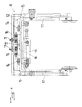
- the coil gripping device is characterized in that it consists of two lateral arms each provided at its free end with a mounting pin of a tube of coil, mounted movably by their other end on a slide support and assembly on a winder and operated at the opening and the closing by means of a cylinder, the mounting of each lateral arm on the support slide and mounting on the winder being performed by the intermediary of a fixed axis of the slide of support and assembly on the winder and cooperating with an oblong hole of the lateral arm, said the support and mounting slide on the winder being further provided with guide stops and stroke limiting cooperating with the end corresponding lateral arms during the opening races and closing said lateral arms.
- this gripping device 10 is advantageously constituted by two lateral arms 11 each provided with its free end of a mounting spindle of a coil tube, mounted mobile manner by their other end on a slide 12 support and mounted on the winder and actuated when opened and closed by via a cylinder 13.
- the mounting of each lateral arm 11 on the slide 12 support and mounting on the winder is performed by through an axis 14 integral with the slideway 12 and cooperating with a oblong hole 15 of the arm 11, said slide 12 being further provided with 16 stops for guiding and limiting stroke cooperating with the end corresponding arms 11 during the opening and closing races said arms 11.
- Such stops 16 guiding and limiting stroke can be formed as pins integral with the slide 12 and penetrating by their free end into corresponding housings of arm 11, a return spring mounted on each pin, or a spring of traction or compression acting on each arm 11, tending to push back said arms 11 to their open or closed position and realizing a automatic centering by balancing the loads exerted on the arms 11.
- the jack 13 is mounted by its clevis on one of the arms 11 and by its piston rod on the other arm 11.
- an actuation of the cylinder 13 would effect is erratic, which is mitigated by the action of the springs of the stops 16 tending to automatically center the arms 11 by compared to the support slide 12.
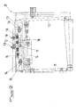
- the slide 12 support and mounting on the winder is preferably mounted on the winder via an axis 17 cooperating with a oblong hole 18 of the support frame of said slide 12, stops adjustable 19 also provided on the winder acting on said slide 12 opposite to the one turned towards the spool, in order to block said slide 12 in its service position.
- the slide 12 can be moved and inclined relative to the winder for the assembly of a conical coil, to bring one of the generators of this coil in a plane parallel to the generator of the tree drive the corresponding coil.
- the slide 12 carrying the arms 11 is firstly displaced with respect to the winder, and then inclined at an angle corresponding to half-angle of taper and is locked in this position by clamping, a part, of the axis 17 cooperating with the oblong hole 18 and, on the other hand, stops 19 relying on said slide 12.
- the support stops 19 on the slide 12 performs the blocking in the inclined position of the slide 12 and therefore the arms 11 of the gripping device 10.
- the receiving pins of coil tube ends are parts Removable and interchangeable mounted in the free ends of the arms 11.
Abstract
Description
La présente invention concerne le domaine de l'industrie textile, en particulier des machines de bobinage de fils et a pour objet un dispositif de préhension de bobine pour de telles machines.The present invention relates to the field of the textile industry, in particular wire winding machines and relates to a device coil grip for such machines.
Actuellement, il existe un dispositif de préhension des tubes de bobines qui se présente sous forme d'un ensemble de vérins et de ressorts agissant de manière symétrique sur deux bras de serrage du tube, ces bras étant montés mobiles en rotation autour d'un point d'articulation. Dans ce dispositif, le serrage du tube est effectué par l'intermédiaire de deux mandrins.Currently, there is a device for gripping coils which is in the form of a set of jacks and springs acting symmetrically on two clamping arms of the tube, these arms being rotatably mounted around a hinge point. In this device, the clamping of the tube is carried out via two mandrels.
Un tel dispositif de préhension présente l'inconvénient de nécessiter un réglage préalable de l'écartement des axes de rotation des bras en fonction de la longueur du tube à serrer entre lesdits bras, ce pour éviter d'endommager ledit tube par un effet de malaxage et de relâcher le fil qui est serré entre lesdits mandrins de manière incorrecte. Par ailleurs, il existe également un risque de diminuer la durée de vie des roulements des mandrins.Such a gripping device has the disadvantage of require a prior adjustment of the spacing of the axes of rotation of the arms depending on the length of the tube to be clamped between said arms, this to avoid to damage said tube by a kneading effect and to release the wire which is clamped between said mandrels incorrectly. Moreover, there is also a risk of reducing the service life of the bearings of mandrels.
On connaít également un dispositif de préhension comportant un bras fixe, qui est cependant réglable en position, et un bras articulé en rotation venant s'appuyer sur l'extrémité libre du tube par l'intermédiaire d'un mandrin.We also know a gripping device comprising a fixed arm, which is however adjustable in position, and an articulated arm rotation coming to rest on the free end of the tube via a mandrel.
Un tel dispositif de préhension présente, toutefois, l'inconvénient de nécessiter un réglage du positionnement du bras fixe pour permettre le centrage du tube sur le poste de bobinage. En outre, dans ce mode de réalisation, la face du mandrin est plaquée de manière imparfaitement parallèle sur le tube, ce qui entraíne les mêmes problèmes d'endommagement du tube, de relâchement du fil et de durée de vie des roulements du mandrin.Such a gripping device presents, however, the disadvantage of requiring adjustment of the positioning of the fixed arm to allow the centering of the tube on the winding station. In addition, in this embodiment, the face of the mandrel is plated so imperfectly parallel on the tube, which causes the same problems damage to the tube, loosening of the wire and the life of the mandrel bearings.
La présente invention a pour but de pallier ces inconvénients en proposant un dispositif de préhension de bobine en particulier pour des machines de bobinage de fils permettant une adaptation simple et rapide à tous types de tubes et de bobines à réaliser.The present invention aims to overcome these disadvantages by proposing a coil gripping device in particular for yarn winding machines allowing quick and easy adaptation to all types of tubes and coils to be made.
A cet effet, le dispositif de préhension de bobine conforme à l'invention est caractérisé en ce qu'il est constitué par deux bras latéraux pourvus chacun à son extrémité libre d'une broche de montage d'un tube de bobine, montés de manière mobile par leur autre extrémité sur une glissière de support et de montage sur un bobinoir et actionnés à l'ouverture et à la fermeture par l'intermédiaire d'un vérin, le montage de chaque bras latéral sur la glissière de support et de montage sur le bobinoir étant effectué par l'intermédiaire d'un axe solidaire de la glissière de support et de montage sur le bobinoir et coopérant avec un trou oblong du bras latéral, ladite glissière de support et de montage sur le bobinoir étant munie, en outre, de butées de guidage et de limitation de course coopérant avec l'extrémité correspondante des bras latéraux pendant les courses d'ouverture et de fermeture desdits bras latéraux.For this purpose, the coil gripping device according to the invention is characterized in that it consists of two lateral arms each provided at its free end with a mounting pin of a tube of coil, mounted movably by their other end on a slide support and assembly on a winder and operated at the opening and the closing by means of a cylinder, the mounting of each lateral arm on the support slide and mounting on the winder being performed by the intermediary of a fixed axis of the slide of support and assembly on the winder and cooperating with an oblong hole of the lateral arm, said the support and mounting slide on the winder being further provided with guide stops and stroke limiting cooperating with the end corresponding lateral arms during the opening races and closing said lateral arms.
L'invention sera mieux comprise, grâce à 1a description ci-après,
qui se rapporte à un mode de réalisation préféré, donné à titre
d'exemple non limitatif, et expliqué avec référence aux dessins
schématiques annexés, dans lesquels :
Conformément à l'invention, ce dispositif de préhension 10 est
avantageusement constitué par deux bras latéraux 11 pourvus chacun à son
extrémité libre d'une broche de montage d'un tube de bobine, montés de
manière mobile par leur autre extrémité sur une glissière 12 de support et de
montage sur le bobinoir et actionnés à l'ouverture et à la fermeture par
l'intermédiaire d'un vérin 13. Le montage de chaque bras latéral 11 sur la
glissière 12 de support et de montage sur le bobinoir est effectué par
l'intermédiaire d'un axe 14 solidaire de la glissière 12 et coopérant avec un
trou oblong 15 du bras 11, ladite glissière 12 étant munie, en outre, de
butées 16 de guidage et de limitation de course coopérant avec l'extrémité
correspondante des bras 11 pendant les courses d'ouverture et de fermeture
desdits bras 11.According to the invention, this
De telles butées 16 de guidage et de limitation de course
peuvent être constituées sous forme de broches solidaires de la glissière 12
et pénétrant par leur extrémité libre dans des logements correspondants des
bras 11, un ressort de rappel monté sur chaque broche, ou un ressort de
traction ou de compression agissant sur chaque bras 11, tendant à repousser
lesdits bras 11 vers leur position d'ouverture ou de fermeture et réalisant un
centrage automatique par équilibrage des charges exercées sur les bras 11.
Le vérin 13 est monté par sa chape sur l'un des bras 11 et par sa
tige de piston sur l'autre bras 11. Ainsi, un actionnement du vérin 13 aurait
pour effet un fonctionnement erratique, qui est pallié par l'action des
ressorts des butées 16 tendant à centrer automatiquement les bras 11 par
rapport à la glissière 12 de support.The
Conformément à une autre caractéristique de l'invention, la
glissière 12 de support et de montage sur le bobinoir est préférentiellement
montée sur 1e bobinoir par l'intermédiaire d'un axe 17 coopérant avec un
trou oblong 18 du châssis de support de ladite glissière 12, des butées
réglables 19 également prévues sur le bobinoir agissant sur ladite glissière
12 de son côté opposé à celui tourné vers 1a bobine, afin de bloquer ladite
glissière 12 dans sa position de service. Ainsi, comme le montre la figure 5
des dessins annexés, la glissière 12 peut être déplacée et inclinée par rapport
au bobinoir en vue du montage d'une bobine conique, afin d'amener une des
génératrices de cette bobine dans un plan parallèle à la génératrice de l'arbre
d'entraínement de la bobine correspondant.According to another characteristic of the invention, the
A cet effet, la glissière 12 portant les bras 11 est d'abord
déplacée par rapport au bobinoir, puis inclinée d'un angle correspondant au
demi-angle de conicité et est bloquée dans cette position par serrage, d'une
part, de l'axe 17 coopérant avec le trou oblong 18 et, d'autre part, des butées
19 s'appuyant sur ladite glissière 12. L'appui des butées 19 sur la glissière
12 réalise 1e blocage en position inclinée de la glissière 12 et donc des bras
11 du dispositif de préhension 10.For this purpose, the
Bien entendu, pour la mise en oeuvre de bobines coniques, les
broches de réception des extrémités de tube de bobines sont des pièces
amovibles et interchangeables montées dans les extrémités libres des bras
11.Of course, for the implementation of conical coils, the
receiving pins of coil tube ends are parts
Removable and interchangeable mounted in the free ends of the
Grâce à l'invention, il est possible de réaliser un dispositif de préhension de bobine en particulier pour des machines de bobinage de fils pouvant facilement être réglé en vue de son adaptation à tous types de bobines à réaliser. Thanks to the invention, it is possible to produce a device for coil gripping especially for wire winding machines can easily be adjusted for adaptation to all types of coils to realize.
Bien entendu, l'invention n'est pas limitée au mode de réalisation décrit et représenté aux dessins annexés. Des modifications restent possibles, notamment du point de vue de 1a constitution des divers éléments ou par substitution d'équivalents techniques, sans sortir pour autant du domaine de protection de l'invention.Of course, the invention is not limited to the mode of embodiment described and shown in the accompanying drawings. Modifications remain possible, particularly from the point of view of the constitution of the various elements or by substituting technical equivalents, without going out for as much of the field of protection of the invention.
Claims (4)
Applications Claiming Priority (2)
| Application Number | Priority Date | Filing Date | Title |
|---|---|---|---|
| FR0112012 | 2001-09-17 | ||
| FR0112012A FR2829754B1 (en) | 2001-09-17 | 2001-09-17 | TRANSFORMER ON SITE |
Publications (3)
| Publication Number | Publication Date |
|---|---|
| EP1293462A2 true EP1293462A2 (en) | 2003-03-19 |
| EP1293462A3 EP1293462A3 (en) | 2003-09-03 |
| EP1293462B1 EP1293462B1 (en) | 2004-05-26 |
Family
ID=8867368
Family Applications (2)
| Application Number | Title | Priority Date | Filing Date |
|---|---|---|---|
| EP20020360265 Expired - Lifetime EP1293463B1 (en) | 2001-09-17 | 2002-09-13 | On-site transformable take-up winder |
| EP02360266A Expired - Lifetime EP1293462B1 (en) | 2001-09-17 | 2002-09-13 | Bobbin holder support structure for winding machines |
Family Applications Before (1)
| Application Number | Title | Priority Date | Filing Date |
|---|---|---|---|
| EP20020360265 Expired - Lifetime EP1293463B1 (en) | 2001-09-17 | 2002-09-13 | On-site transformable take-up winder |
Country Status (4)
| Country | Link |
|---|---|
| EP (2) | EP1293463B1 (en) |
| DE (2) | DE60200034T2 (en) |
| FR (1) | FR2829754B1 (en) |
| TR (2) | TR200401897T4 (en) |
Cited By (2)
| Publication number | Priority date | Publication date | Assignee | Title |
|---|---|---|---|---|
| CN112299133A (en) * | 2020-10-26 | 2021-02-02 | 南京理工大学 | Bunching device for electrical engineering cable |
| CN113562542A (en) * | 2021-07-30 | 2021-10-29 | 泉州市集华针纺科技有限公司 | Mixed spinning mechanism for knitted fabric production and processing technology |
Families Citing this family (1)
| Publication number | Priority date | Publication date | Assignee | Title |
|---|---|---|---|---|
| CN104001638B (en) * | 2014-06-11 | 2017-02-15 | 南京横空机械设备制造有限公司 | Mechanical spraying production line with functions of automatic line transferring, piece loading and piece uploading |
Citations (4)
| Publication number | Priority date | Publication date | Assignee | Title |
|---|---|---|---|---|
| FR2098134A5 (en) * | 1970-06-30 | 1972-03-03 | Asahi Chemical Ind | |
| JPS5167431A (en) * | 1974-12-02 | 1976-06-11 | Daiwa Spinning Co Ltd | KUREEDORU |
| DE3246314A1 (en) * | 1982-12-11 | 1984-06-14 | KMB Kabel-Maschinen-Berlin GmbH, 1000 Berlin | Device for mounting of reels |
| GB2139656A (en) * | 1983-05-13 | 1984-11-14 | Hollingsworth | Package holder in a yarn winder |
Family Cites Families (6)
| Publication number | Priority date | Publication date | Assignee | Title |
|---|---|---|---|---|
| FR2202511A5 (en) * | 1972-10-11 | 1974-05-03 | Superba Ste | Yarn winding device for conical packages - has compensating device to automatically adjust yarn tension according to position on bobbin |
| US4062503A (en) * | 1976-08-30 | 1977-12-13 | Haskell Electronics & Tool Corporation | Level winding apparatus |
| AU2595484A (en) * | 1983-04-07 | 1984-10-11 | Martin Processing Inc. | Yarn winding onto spool |
| CH666243A5 (en) * | 1984-11-19 | 1988-07-15 | Schweiter Ag Maschf | WINDING MACHINE WITH AT LEAST TWO SPOOLS FOR PRODUCING THE WINDING OF A CROSS REEL. |
| DE4125310A1 (en) * | 1990-08-16 | 1992-02-20 | Barmag Barmer Maschf | False twisted yarn cross wound bobbin - is wound by dividing total winding time into sections for surface speed control independently of other yarn feeds |
| DE19921630A1 (en) * | 1999-05-10 | 2000-11-16 | Stahlecker Fritz | Traverse drive for winding cross-wound packages uses a linear electric motor |
-
2001
- 2001-09-17 FR FR0112012A patent/FR2829754B1/en not_active Expired - Fee Related
-
2002
- 2002-09-13 DE DE2002600034 patent/DE60200034T2/en not_active Expired - Lifetime
- 2002-09-13 TR TR2004/01897T patent/TR200401897T4/en unknown
- 2002-09-13 EP EP20020360265 patent/EP1293463B1/en not_active Expired - Lifetime
- 2002-09-13 EP EP02360266A patent/EP1293462B1/en not_active Expired - Lifetime
- 2002-09-13 DE DE2002600541 patent/DE60200541T2/en not_active Expired - Lifetime
- 2002-09-13 TR TR2003/02087T patent/TR200302087T4/en unknown
Patent Citations (4)
| Publication number | Priority date | Publication date | Assignee | Title |
|---|---|---|---|---|
| FR2098134A5 (en) * | 1970-06-30 | 1972-03-03 | Asahi Chemical Ind | |
| JPS5167431A (en) * | 1974-12-02 | 1976-06-11 | Daiwa Spinning Co Ltd | KUREEDORU |
| DE3246314A1 (en) * | 1982-12-11 | 1984-06-14 | KMB Kabel-Maschinen-Berlin GmbH, 1000 Berlin | Device for mounting of reels |
| GB2139656A (en) * | 1983-05-13 | 1984-11-14 | Hollingsworth | Package holder in a yarn winder |
Cited By (2)
| Publication number | Priority date | Publication date | Assignee | Title |
|---|---|---|---|---|
| CN112299133A (en) * | 2020-10-26 | 2021-02-02 | 南京理工大学 | Bunching device for electrical engineering cable |
| CN113562542A (en) * | 2021-07-30 | 2021-10-29 | 泉州市集华针纺科技有限公司 | Mixed spinning mechanism for knitted fabric production and processing technology |
Also Published As
| Publication number | Publication date |
|---|---|
| FR2829754A1 (en) | 2003-03-21 |
| DE60200541D1 (en) | 2004-07-01 |
| DE60200034T2 (en) | 2005-02-10 |
| DE60200034D1 (en) | 2003-10-23 |
| TR200302087T4 (en) | 2004-02-23 |
| EP1293463A1 (en) | 2003-03-19 |
| TR200401897T4 (en) | 2004-09-21 |
| EP1293463B1 (en) | 2003-09-17 |
| FR2829754B1 (en) | 2003-11-28 |
| DE60200541T2 (en) | 2005-08-18 |
| EP1293462A3 (en) | 2003-09-03 |
| EP1293462B1 (en) | 2004-05-26 |
Similar Documents
| Publication | Publication Date | Title |
|---|---|---|
| FR2695616A1 (en) | Bicycle brake with articulated levers. | |
| EP0034688A2 (en) | Machine for stringing rackets | |
| FR2553076A1 (en) | TENSIONING DEVICE FOR WIND COIL WINDING MACHINE | |
| EP1293462B1 (en) | Bobbin holder support structure for winding machines | |
| EP0371919A1 (en) | Sewing machine | |
| EP1364853A1 (en) | Support and guiding device for the cable of a transport system | |
| FR2769302A1 (en) | Lever clamp for moving load without manual contact | |
| FR2532960A1 (en) | ||
| EP0771931A1 (en) | Safety device for ladder and ladder incorporating the same | |
| BE1007884A3 (en) | Edge training device and entry leads for looms. | |
| FR2504561A1 (en) | BRAKING DEVICE FOR SPINDLE AND SPINDLE PINS | |
| FR2796056A1 (en) | Wire feed for a machine tool has a motor drive to rotate the bobbin controlled by wire tension monitors as the wire deflection guides from the bobbin towards the machine tool | |
| FR2539765A1 (en) | MACHINE FOR THE WIRING OF WIRES AND ESPECIALLY GLASS WIRES | |
| FR2816234A1 (en) | SUSPENSION DEVICE FOR A BLADE OF A PARALLELOGRAM CHANNEL SAW | |
| FR2610646A1 (en) | DEVICE FOR CUTTING FRAME WIRE FOR WEAVING | |
| FR2673586A1 (en) | MACHINE FOR THE MAINTENANCE OF A CONTACT LINE. | |
| FR2523803A1 (en) | CHARRUE PORTEE BRABANT | |
| CH644329A5 (en) | DEVICE FOR PERFORMING SEPARATION OF THE TERMINAL PARTS OF CONDUCTIVE WIRES IN AN AUTOMATIC WINDING MACHINE. | |
| EP0304465A1 (en) | Device for knotting a flexible tie | |
| US6729574B2 (en) | Gripping device for package, in particular for yarn winding machines | |
| FR2620361A1 (en) | TILT BLADE BAND SAW | |
| FR2622129A1 (en) | Machine for shaping a section of wire or of tube by successive bending operations | |
| FR2545464A1 (en) | Automatic yarn-reel unwinding and regulating apparatus, for a loom, yarn guide (carrier), pirn (bobbin) winder or other devices | |
| FR2794136A1 (en) | Spinning machine, sewing machine, etc. has bobbins mounted on rack moved between loading and operating positions by hydraulic or pneumatic jack operating pantograph mechanism | |
| FR2534235A1 (en) | Clamp for handling spools. |
Legal Events
| Date | Code | Title | Description |
|---|---|---|---|
| PUAI | Public reference made under article 153(3) epc to a published international application that has entered the european phase |
Free format text: ORIGINAL CODE: 0009012 |
|
| AK | Designated contracting states |
Kind code of ref document: A2 Designated state(s): AT BE BG CH CY CZ DE DK EE ES FI FR GB GR IE IT LI LU MC NL PT SE SK TR Designated state(s): AT BE BG CH CY CZ DE DK EE ES FI FR GB GR IE IT LI LU MC NL PT SE SK TR |
|
| AX | Request for extension of the european patent |
Extension state: AL LT LV MK RO SI |
|
| PUAL | Search report despatched |
Free format text: ORIGINAL CODE: 0009013 |
|
| AK | Designated contracting states |
Kind code of ref document: A3 Designated state(s): AT BE BG CH CY CZ DE DK EE ES FI FR GB GR IE IT LI LU MC NL PT SE SK TR |
|
| AX | Request for extension of the european patent |
Extension state: AL LT LV MK RO SI |
|
| 17P | Request for examination filed |
Effective date: 20031003 |
|
| GRAP | Despatch of communication of intention to grant a patent |
Free format text: ORIGINAL CODE: EPIDOSNIGR1 |
|
| RAP1 | Party data changed (applicant data changed or rights of an application transferred) |
Owner name: SUPERBA (SOCIETE PAR ACTIONS SIMPLIFIEE) |
|
| GRAS | Grant fee paid |
Free format text: ORIGINAL CODE: EPIDOSNIGR3 |
|
| GRAA | (expected) grant |
Free format text: ORIGINAL CODE: 0009210 |
|
| AK | Designated contracting states |
Kind code of ref document: B1 Designated state(s): BE DE FR GB IT TR |
|
| AKX | Designation fees paid |
Designated state(s): BE DE FR GB IT TR |
|
| REG | Reference to a national code |
Ref country code: GB Ref legal event code: FG4D Free format text: NOT ENGLISH |
|
| REG | Reference to a national code |
Ref country code: IE Ref legal event code: FG4D Free format text: FRENCH |
|
| REF | Corresponds to: |
Ref document number: 60200541 Country of ref document: DE Date of ref document: 20040701 Kind code of ref document: P |
|
| GBT | Gb: translation of ep patent filed (gb section 77(6)(a)/1977) |
Effective date: 20040812 |
|
| REG | Reference to a national code |
Ref country code: IE Ref legal event code: FD4D |
|
| PLBE | No opposition filed within time limit |
Free format text: ORIGINAL CODE: 0009261 |
|
| STAA | Information on the status of an ep patent application or granted ep patent |
Free format text: STATUS: NO OPPOSITION FILED WITHIN TIME LIMIT |
|
| 26N | No opposition filed |
Effective date: 20050301 |
|
| PGFP | Annual fee paid to national office [announced via postgrant information from national office to epo] |
Ref country code: GB Payment date: 20120918 Year of fee payment: 11 |
|
| PGFP | Annual fee paid to national office [announced via postgrant information from national office to epo] |
Ref country code: IT Payment date: 20120926 Year of fee payment: 11 |
|
| PGFP | Annual fee paid to national office [announced via postgrant information from national office to epo] |
Ref country code: FR Payment date: 20121012 Year of fee payment: 11 |
|
| GBPC | Gb: european patent ceased through non-payment of renewal fee |
Effective date: 20130913 |
|
| REG | Reference to a national code |
Ref country code: FR Ref legal event code: ST Effective date: 20140530 |
|
| PG25 | Lapsed in a contracting state [announced via postgrant information from national office to epo] |
Ref country code: GB Free format text: LAPSE BECAUSE OF NON-PAYMENT OF DUE FEES Effective date: 20130913 |
|
| PG25 | Lapsed in a contracting state [announced via postgrant information from national office to epo] |
Ref country code: IT Free format text: LAPSE BECAUSE OF NON-PAYMENT OF DUE FEES Effective date: 20130913 Ref country code: FR Free format text: LAPSE BECAUSE OF NON-PAYMENT OF DUE FEES Effective date: 20130930 |
|
| PGFP | Annual fee paid to national office [announced via postgrant information from national office to epo] |
Ref country code: DE Payment date: 20190913 Year of fee payment: 18 |
|
| PGFP | Annual fee paid to national office [announced via postgrant information from national office to epo] |
Ref country code: BE Payment date: 20190925 Year of fee payment: 18 |
|
| REG | Reference to a national code |
Ref country code: DE Ref legal event code: R119 Ref document number: 60200541 Country of ref document: DE |
|
| REG | Reference to a national code |
Ref country code: BE Ref legal event code: MM Effective date: 20200930 |
|
| PG25 | Lapsed in a contracting state [announced via postgrant information from national office to epo] |
Ref country code: DE Free format text: LAPSE BECAUSE OF NON-PAYMENT OF DUE FEES Effective date: 20210401 |
|
| PG25 | Lapsed in a contracting state [announced via postgrant information from national office to epo] |
Ref country code: BE Free format text: LAPSE BECAUSE OF NON-PAYMENT OF DUE FEES Effective date: 20200930 |
|
| PGFP | Annual fee paid to national office [announced via postgrant information from national office to epo] |
Ref country code: TR Payment date: 20210824 Year of fee payment: 20 |