EP0034688A2 - Machine for stringing rackets - Google Patents
Machine for stringing rackets Download PDFInfo
- Publication number
- EP0034688A2 EP0034688A2 EP80401621A EP80401621A EP0034688A2 EP 0034688 A2 EP0034688 A2 EP 0034688A2 EP 80401621 A EP80401621 A EP 80401621A EP 80401621 A EP80401621 A EP 80401621A EP 0034688 A2 EP0034688 A2 EP 0034688A2
- Authority
- EP
- European Patent Office
- Prior art keywords
- hose
- machine according
- rotation
- axis
- clamp
- Prior art date
- Legal status (The legal status is an assumption and is not a legal conclusion. Google has not performed a legal analysis and makes no representation as to the accuracy of the status listed.)
- Withdrawn
Links
Images


Classifications
-
- A—HUMAN NECESSITIES
- A63—SPORTS; GAMES; AMUSEMENTS
- A63B—APPARATUS FOR PHYSICAL TRAINING, GYMNASTICS, SWIMMING, CLIMBING, OR FENCING; BALL GAMES; TRAINING EQUIPMENT
- A63B51/00—Stringing tennis, badminton or like rackets; Strings therefor; Maintenance of racket strings
- A63B51/14—Arrangements for stringing, e.g. for controlling the tension of the strings during stringing
Definitions
- the present invention relates to a racket stringing machine.
- the object of the present invention is to provide a stringing machine overcoming the drawbacks of these widely used machines.
- the invention provides a machine ensuring the tensioning of the hose, at an upright or across the racket, by linear movement of a carriage with which the free end of the hose is secured. , the other end of it being secured to the frame of the racket; the movement of the carriage is advantageously controlled by electromechanical means with electronic control, according to a constant comparison between the instantaneous tension of the hose, which is imposed by the movement of the carriage, and a predetermined tension according to the desired characteristics of the racket and the sport for which it is intended.
- Such a machine is naturally much more comfortable to use than a machine using weights, and is considerably more sensitive on the one hand because it completely eliminates the influence of human factors and on the other hand because of the possibility that it offers a wide use of electronics.
- another object of the invention is to make the whole machine adaptable to all types of rackets, whatever their shape or their dimensions; for this purpose, in a preferred embodiment, the invention provides means for adjusting the cradle immobilizing at will on the machine the racket during stringing, which makes the machine according to the invention truly universal.
- the machine according to the invention can be produced in a particularly simple and economical manner, and in a small footprint, despite its much greater possibilities in terms of precision and in the range of possible settings to those of currently known machines.
- the present machine is also designed to be able to move the clamp, and put it in position relative to the hose to be immobilized temporarily over the entire surface defined by the frame of the racket.
- the stringing machine is characterized in that the said means for temporarily immobilizing the hose under tension comprise two substantially horizontal arms, movable in rotation around vertical axes diametrically opposite with respect to the disc, located at heights neighboring, of length less than the distance between the two axes, the crossing point of which describes at least the entire lower surface of the frame that racket.
- FIGS. 1 to 6 correspond to a state of rest of the machine, that is to say to a state prior to the tensioning of a section of hose corresponding to an upright or across the racket.
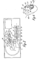
- Figure 1 there is shown schematically in broken line a racket 1 and in broken line a hose 2, which, for example, the machine according to the invention is ready to tension a section corresponding to an amount.
- the machine comprises means 3 adjustable on the one hand in order to adapt to all the shapes and dimensions of racket, and thus make it possible to make the best use of the wide possibilities of the tensioning system. which will be described later, and on the other hand to allow the orientation of the racket 1 as a function of the position of the upright or the cross to be tensioned.
- the means 3 include, on the horizontal upper face 5 of the base 6 of the machine, a horizontal table 4 completely of revolution around an axis 7 fixed relative to the base 6, on which the table 4 is mounted at free rotation around this axis 7.
- the table 4 has the shape of a disc, the upper face 8 est.plane and whose lower face 9 carries, set back towards the axis 7 relative to its circular periphery 10, a skirt continuous 11, internally and externally cylindrical of revolution around the axis 7.
- the cylindrical outer periphery of the skirt 11 carries two identical arms, respectively 12 and 13, essentially vertical and forming above the upper face 8 of the table 4 a projection of identical height, for the reasons which will appear further on, each of the arms 12 and 13 is connected to the cylindrical outer periphery of the skirt 11 by a horizontal, radial rim, such as 14, which on the one hand keeps the arm at a distance from the periphery 10 and on the other hand, being located at a distance from the face 9, also clears the zone of the latter situated between the cylindrical outer periphery of the skirt 11 and the periphery 10.
- each of the arms 12 and 13 carries a half cradle in the form of a horizontal crescent, respectively 15 and 16, the two half cradles 15 and 16 whose concavities face each other substantially resume the form of two opposite zones of the frame of a racket so as to be able to carry such a frame by said zones thereof.
- the two half-cradles 15 and 16 have coplanar horizontal upper faces, respectively 17 and 18, and each has a plurality of vertical orifices, respectively 19 and 20, distributed on its upper face to allow mounting on that -this, in the most appropriate positions taking into account the shape and dimensions of the frame of a racket to be strung, of horizontal jacks, such as respectively 21 and 22, capable of bearing on the outer periphery of the frame of the racket to immobilize it on the assembly constituted by the half-cradles 15 and 16; in addition, in view of this immobilization is provided in the concavity of each half-cradle, in diametrically opposite positions with respect to the axis 7 and projecting above the faces 17 and 18, a hook, respectively 23 and 24 , capable of being supported centrifugally on the inner periphery of the racket frame; for this purpose, each of the hooks 23 and 24 is adjustable in a radial direction, relative to the corresponding half-cradle, by means of a
- the two half-cradles 15 and 16 are also mounted on the upper ends of the arms 12 and 13, respectively by means allowing their adjustment. in position in the same radial, horizontal direction.
- FIG. 3 illustrates the arm 12 to which the arm 13 is identical.
- FIG. 3 shows a view of the arm 12 in a radial direction, towards the axis 7; it appears that the arm 12 has upward a flat, horizontal upper face 27 inside which is arranged a dovetail groove 28, horizontal, radially oriented; additionally, the half-cradle 15 has a flat, horizontal lower face 29, suitable for resting by one of its zones on the upper face 27 of the arm 12, and a rib 30 oriented radially, horizontally, and forming under the face 29 a projection whose dovetail profile is complementary to that of the groove 28; inside this rib 30 is arranged a channel 31 inside which can slide a rod 32 integral with the lug 23 in the concavity of the half-cradle 15 and carrying at the level of the convexity thereof the button softness 25, able to be screwed more or less on the rod 32, by rotation, to adjust the position of the lug 23 relative to the half-cradle 15.
- the half-cradle 15 can slide in a horizontal, radial direction, on the horizontal upper face 27 of the arm 12, to allow immobilization in a position best suited to the shape and dimensions of the frame of the racket to be strung
- the arm 12 is designed as a clamp and has for this purpose a vertical slot 33 passing right through it along a plane including the axis 7 and the axis of the split of the groove 28, the slot 33 originating at the bottom of this groove and extending over most of the height of the arm 12;
- this slot 33 defines at the upper part of the arm 12 two jaws, respectively 34 and 35, each of which corresponds to one of the sides of the groove 28; immobilization at will of the rib 30 in the groove 28 is ensured by tightening the two jaws 34 and 35, by means of a screw passing through them right through in a direction 36 perpendicular to the mean plane of the slot 33 (this screw has not been shown); it will be noted that, given the arcuate shape of the groove 28 and of the rib 30,
- the machine comprises, in a zone always situated outside the cradle constituted by the two half-cradles 15 and 16, that is to say outside the table 4, means d anchoring 37 for the hose, which are carried by an assembly 38 for tensioning this hose which will be described later.
- a rotation of the table 4 around its axis 7 makes it possible to present the racket successively in the positions, vis-à-vis the anchoring means 37 and the tensioning assembly 38, the most suitable for the successive stringing respectively of each upright and of each crosspiece;
- the most suitable position for stringing an upright or a crosspiece corresponds to a position where the section of hose to be tensioned is immobilized in a first zone of the racket frame, free to slide relative to a second zone thereof, and temporarily secured to the anchoring means 37 beyond this second zone relative to the first, with a shape as close to the rectilinear shape as possible.
- braking means 39 which will now be described more particularly with reference to FIG. 2.
- braking means 39 are manually controlled by a handle 40 situated above the face 5 of the base 6 and movable in rotation about a vertical axis relative to the latter, between three notched positions corresponding respectively to total freedom of the table 4 rotating around the axis 7, to a soft braking position allowing manual rotation of the table 4 around the axis 7 with reduced effort, for reasons of working convenience, and a position d firm immobilization of the table 4 relative to the base 6, during a tensioning operation.
- the braking means 39 are illustrated in FIG. 2 in the first of these three positions.
- the braking means 39 comprise a horizontal lever 42 articulated at one of its ends around a vertical axis 41 fixed relative to the base 6 of the machine and disposed relative to the axis 7 of such that, in its three positions corresponding to the three notched positions of the handle 40, the lever 42 is oriented along a cord of the cylindrical inner periphery of the skirt 11 of the table 4, at a level slightly lower than the lower level of this skirt.
- the lever 42 At its second end, curved upwards and passing through the horizontal upper wall 44 of the base 6 via a slot 45 in the latter, the lever 42 carries a shoe 43 placed opposite the cylindrical inner periphery of the skirt 11; the application of the pad 43 against this inner periphery results, as a function of the pressure with which it takes place, by gentle or vigorous braking of the table 4.
- the lever 42 carries on the one hand an anchoring point 45bfor one end of a coil spring 46 whose other end is connected to a point 47 fixed relative to the base 6, in a position such that this spring 46 applies to the lever 42 a constant elastic traction tending to make it pivot about the axis 41 in the direction of an application of the pad 43 against the cylindrical inner periphery of the skirt 11 of the table 4, and on the other hand a vertical lug 48 engaged in an oblong slot 49 of a horizontal link 50 connecting between the lever 42 and a cam 51 integral in rotation with the handle 40 around a vertical axis 52, inside the base 6 ; the rod 50 is articulated on this cam 51, at one of its ends, opposite its end carrying the light 49, around a vertical axis 53 eccentric relative to the axis 52.
- the cam 51 is located on the same side of the lever 42 as the zone of the cylindrical inner periphery of the skirt 11 against which the shoe 43 must be applied, with respect to this shoe 43, and the operation of the braking means 39- is the following.
- the axis 53 is located between the axis 52 and the lever 42 and the link 50 applies to the lug 48, then in contact with the end of the lumen 49 closest to the axis 53, a thrust keeping the shoe 43 at a distance from the cylindrical inner periphery of the skirt 11;
- this first position corresponds to the engagement, in a first notch 54 of the otherwise circular periphery of the cam 51, of a roller 55 which suitable means tend to resiliently approach the axis 52, centers the periphery of the cam 51.
- Appropriate means 59 are provided to allow adjustment of the length of the rod 50 so that each of the three notched positions of the cam 51 effectively corresponds to one of the positions of the shoe 43 defined above; the movement of the shoe 43 accompanying the rotation of the cam 51 in the direction of the arrow 56 is shown diagrammatically by a arrow 60 in FIG. 2.
- FIG. 2 shows preferred means for imparting to the anchoring means 37, in accordance with the invention, a translational movement substantially parallel to the mean plane of the racket immobilized on the two half-cradles 15 and 16, this movement resulting in the tensioning of a section of the hose.
- these means comprise an electric motor 62, the output shaft of which is engaged, if necessary by means of a set of reduction gears 63, with a screw 64 which it rotates, at will in one direction or the other, about its horizontal axis 65 oriented in the direction of translation of the desired anchoring means 37 (this direction is that of arrow 66 in FIG. 1 and of arrow 67 in FIG. 2, these arrows indicating the direction of translation of the anchoring means 37 corresponding to an increase in the tension of the hose).
- the thread of the screw 64 is engaged with a nut 68 which in turn is fixed in rotation relative to the base 6 of the machine, so that the rotation of the screw 64 respectively in one direction or the other results in a translation of the nut 68 parallel to the axis 65, respectively in one direction or the other.
- This nut 68 is integral with a carriage 69 guided in translation parallel to the axis 65 relative to the base 6, for example by means of two rectilinear, fixed slides, 70 and 71 parallel to this axis 65; the slides 70 and 71 are for example defined by rectilinear rods around which slide complementary sleeves of the carriage 69, which are advantageously lined internally with any material improving the sliding.
- the carriage 69 integrally carries a casing 72 which itself carries anchoring means 37; this casing 72 passes through the upper wall 44 of the base 6 via an oblong slot 73 selcn a direction parallel to that of the axis 65, so as to allow the movement of the assembly formed by the carriage 69 and the casing 72 in this direction following the rotation of the screw 64; advantageously, the area of the light 73 released when the casing 72 occupies a determined position is obscured by a shutter sliding along the wall 44 integrally with the carriage 69.
- the casing 72 has the dual role of transmitting the translational movement of the carriage 69 to the anchoring means 37, and of protecting the means of comparison of the instantaneous tension of the hose with a predetermined adjustable tension.
- the casing 72 comprises two vertical cheeks 74 and 75, mutually parallel and parallel to the direction of movement of the carriage 69 of which they are directly integral through the lumen 73, and a cover 76 removed from FIGS. 4 and 5.
- the two cheeks 74 and 75 carry bearings, respectively 78 and 79, defining an axis of rotation 77, horizontal and situated in a plane perpendicular to the direction of movement of the carriage 69, for a shaft 80 for the essential cylindrical of revolution around this axis 77.
- This shaft 80 crosses the cheek 74 from side to side, and carries in its zone situated outside the interval between the two cheeks the means 37 for anchoring the hose.
- These means 37 are designed such that the tensioning of the hose by translation of the assembly 38 in the direction of the arrow 66 tends, by reaction, to rotate the integral assembly formed by these means 37 and the shaft 80 around the axis 77, with respect to the cheeks 74 and 75, in the direction of the arrow 81 in FIG. 5.
- the means 37 consist of a self-tightening clamp comprising a jaw 82 integral with the axis 80 and a jaw 83 articulated on the jaw 82, these two jaws jointly defining a periphery 84 slightly frustoconical of revolution around the axis 77 for receiving the winding hose and, between them, a slot 85 able to receive a strand of the hose and to immobilize it by pinching, because the winding on the periphery 84 results in a tightening of the jaws.
- the periphery 84 Along its upper generatrix, which corresponds to an area of the jaw 82, the periphery 84 carries two neighboring nipples 86 defining between them a precise position of the area of the hose 2 wound around the periphery 84 to ensure the clamping of the clamp .
- the shaft 80 carries down a flat 87 against which is secured an end 88 flattened by a spiral spring 89, describing at mins a portion of turn around the cylindrical periphery of the shaft 80 and comprising a second flat end 90 abutting against the periphery of a roller 91 mounted in free rotation, about its axis 92, parallel to the axis 77, on the "cheek 74; the spring 89, the flat 87 and the roller 91 are arranged such that the spring tends to apply to the shaft 80 an elastic return in the opposite direction to the direction of the arrow 81 when the tensioning of the hose by displacement of the assembly 38 in the direction of arrow 66 tends to cause joint rotation of the anchoring means 37 and of the shaft 80 in the direction of this arrow 81.
- Means other than a spiral spring 89 could be used to force the shaft 80 to react to the action of the tensioned hose, but it will be noted that a spiral spring such as 89 has the advantage of being deformed linearly as a function of a torque of axis 77 which is imposed on it, which means in other words, since the effect of the tension of the hose and that of the spiral spring 89 is balanced at all times, that the instantaneous value of the rotation of the anchoring means 37 about the axis 77 with respect to a position corresponding to a zero tension of the hose and a zero tension of the spiral spring 89 is a linear function of the instantaneous value of the tension of the hose, which facilitates the display of the predetermined voltage to be established therein, as will be described later.
- the shaft 80 carries integrally, downwards, near the cheek 75, a member 95 including an edge 96, oriented upstream taking into account the direction of the arrow 81, is applied against the stop 93 when the spring tension is zero, and a second edge 97 of which, oriented downstream taking account of the direction of the arrow 81, is applied against the stop 94 when the tension of the spiral spring 89 is maximum, which corresponds to a maximum voltage applicable to a hose by means of the machine according to the invention, that is to say for example to an effort of thirty kilos.
- the member 95 is partially delimited, at its lower part, by an edge 98 of revolution around the axis 77 and carrying a gear toothing, complementary to that of a pinion 99 mounted for rotation on the plays 75 around an axis 100 parallel to axis 77; the reduction between the member 95 and the pinion 99 is significant, so that the rotation of the member 95 between the two stops 93 and 94 results in a rotation of the pinion 99 about the axis 100 on an angle also as close as possible to three hundred and sixty degrees, in a direction indicated by the arrow 101 in FIG. 5 when the shaft 80 rotates in the direction of the arrow 81, the member 95 naturally rotating in the same direction as the shaft 80 as indicated by arrow 102 in FIG. 5.
- the pinion 99 integrally carries a radial arm 103 whose radius is as large as possible taking into account its possibilities of rotation at inside the cover 76 of the assembly 38.
- this arm 103 carries towards the cheek 74 a rim 104 parallel to the axis 100 and, at the extremity of this rim 104 closest to the cheek 74, it is ie between the arm 103 and this cheek 74, a plate 105 in return towards the axis 100, parallel to the arm 103; this plate 105 constitutes a flag testifying to the instantaneous position of the arm 103 in rotation about the axis 100, that is to say of the instantaneous position of the shaft 80 around the axis 77, that is to say also the instantaneous tension of hose 2.
- Various means can be provided for detecting this instantaneous position of the plate 105, such as for example opto-electronic proximity detectors, a set of two high frequency induction coils arranged on either side of the forced passage of the plate 105 when the arm 103 rotates about the axis 100, the plate 105 or other equivalent means then being designed in the most appropriate manner as a function of these detection means.
- this wafer 105 is made of a material capable of constituting a magnetic screen, it that is to say in soft iron, the arm 103 being in turn made of a non-magnetic material.
- the cheek 74 is traversed right through by a shaft 108 which is essentially cylindrical of revolution around the axis 106, and comprises to facilitate the rotation of this shaft 108 around the axis 106 a bearing 107 .
- the shaft 108 integrally carries a graduated button 109 allowing display, facing a reference 110 affixed on the cheek 74, the tension which it is desired to impose on the hose (see also FIG. 1).
- the position of the button 109 illustrated in FIGS. 4 to 6 corresponds to the display of a zero value of this voltage.
- the shaft 108 Moreover integrally carries a radial disc 111, situated between the cheek 74 and the forced passage of the plate 105 during its rotation around the axis 100, the respective spokes of the disc 111 around the axis 106 and of the arm 103 around the axis 100 being substantially adjacent.
- the disc 111 carries a flexible blade switch 112 controlling the operation of the motor 62, closing the power supply circuit thereof when it is subjected to the action of a magnetic field applied opposite the face of the disc 111 on which it is fixed, to cause the operation of the motor 62 in the direction of drive of the carriage 68 in the direction of the arrow 67, and to open this circuit and stop the motor 62 as instantly as possible when the action of the magnetic field ceases.
- This magnetic field is applied to the flexible blade switch 112, when the plate 105 is not located opposite it, by a permanent magnet 113 carried by an arm 114 radial with respect to the axis 106, and located between the respective compulsory passages of the plate 105 and of the arm 103 during the rotation of the latter around the axis 100.
- the arm 114 is mounted for rotation about the axis 106 relative to the shaft 108, but it is resiliently recalled by a spring 115, in the opposite direction to the direction of an arrow 116 corresponding to the rotation of the integral assembly 111-button disc 109 in the direction of an increasing voltage display, this arrow 116 being in the same direction as arrow 101, against a stop 117 adjustable so that, when the arm 114 is in contact with this stop 117 under the action of the spring 115, the magnet 113 is placed directly opposite the flexible blade switch 112.
- the tensioning of a section of the hose 2 corresponding for example to an upright, as illustrated in FIG. 1, is carried out as follows, the hose being integral with the frame of the racket in its zone the further from the anchoring means 37, depending on the case, definitively for example by knotting or temporarily by means of a flying clamp or a clamp 118 integrated into the machine as will be described below, and free to slide relative to the frame of the racket in its zone closest to the anchoring means 37.
- the anchoring means are fixed 37 a zone of the hose located outside the frame of the racket, in the example illustrated by winding this zone over a few turns around the periphery 84 of the anchoring means 37 and then engaging a zone of the hose close to its zone wound between the two jaws 82 and 83 where it is immobilized by clamping due to the winding.
- Cn then displays by means of the button 109 the voltage to be applied to the section of the intended hose, in the case of the preferred example, illustrated by rotation of the button 109 in the direction of the arrow 116 at an angle proportional to the tension to be established, relative to the position of this button corresponding to the display of a zero voltage.
- the operator then starts the motor 62, by closing a switch 130 also inserted in the supply circuit thereof, to cause a movement of the carriage 69 in the direction of the arrow 67, and jointly a displacement of the tensioning assembly 38, including the anchoring means 37, in the direction of the arrow 66.
- this rotation which takes place in the direction of the arrow 81, is accompanied by a rotation of the arm 103 and of the plate 105 in the direction of the arrow 101, so that the plate 105 progressively approaches of the flexible blade switch 112 and of the magnet 113 always placed opposite one another, then, when the voltage displayed by means of the button 109 is reached, is interposed between these elements 112 and 113 , which causes on the one hand the opening of the power supply circuit of the motor 62, and on the other hand, by a system of preferably electronic relays, the realization of which is within the domain of human knowledge.
- the hose relaxes while the assembly 38 remains stationary, which results in a rotation of the shaft 80 and of the elements which are integral therewith, around the axis 77, in opposite direction of axis 81; this rotation results in releasing the flexible blade switch 112 and the magnet 113 from the action of the wafer 105, which restarts the motor 62 to start to drive the carriage 69 in the direction of the arrow 67, and the tensioning assembly in the direction of arrow 66, until the displayed voltage is reached again, the plate 105 then again interposing between the elements 112 and 113 to cause the abrupt stop of the motor 62 ; this process can be repeated automatically; when a long time elapses between two successive restartings of the motor 62, it is considered that the tension of the hose section is stabilized; we then immobilize with respect to the frame the area of this section initially mounted to slide relative to the latter, for example by means of a flying clamp or of the clamp 118 which will be described later, then the hose
- FIG. 1 Various means can be used to ensure the temporary immobilization of a zone of the hose relative to the frame of the racket, but in FIG. 1 is shown a clamp system specially adapted to the adjustment possibilities of the two half-cradles 15 and 16 according to a very wide range of shapes and dimensions of racket frames.
- This clamp system 118 comprises a clamp proper 119, known in itself, free to slide vertically and in rotation in a vertical sleeve 120 which, according to the invention can be brought then immobilized extremely quickly in any position on the table 4.
- the sleeve 120 is carried integrally by a base 121 capable of sliding radially with respect to the axis 7, on the upper face 8 of the table 4, along a free radial member 122.
- the two rods 123 and 124 are integrally connected on the one hand near the axis 7 by a part 125 mounted for free rotation around this axis, relative to the table 4, but immobilized in translation along this axis, and on the other hand near the periphery 10 of the table 4 by a piece 126 overlapping this periphery and comprising, under the rim defined over the entire periphery of the table 4 by the area of the face 9 of that -this located outside of the skirt 11, two claws 127 and 128 immobilizing this part in trans lation parallel to the axis 7 while allowing its translation along the entire periphery 10 of the table 4, completely cleared for this purpose as has been described above, by rotation of the entire member 122 around axis 7.
- the immobilization in the required position is ensured in a single operation, by means of a shoe placed under the base 121 and that a lever 129 makes it possible to press at will against the upper face 8 of the table 4, the member 125 and the claws 127 and 128 preventing the base 121 from moving away from this face 8.
- These accessory provisions include, for example limit switches, provided in the example illustrated to detect the extreme positions of the carriage 69 and cause automatic switching of the direction of rotation of the motor 62 when one of the limit switches is actuated.
- FIGS. 4 and 6 have illustrated, in particular, a safety device preventing a false manual operation of the operator from causing the voltage displayed on the screen to be exceeded. by means of button 109.
- means are provided such that the plate 105 projects, when it is rotated in the direction of the arrow 101, from the position where it is interposed between the magnet 113 and the flexible blade switch 112 does not cause the motor 62 to be restarted in the direction of increasing voltages.
- the arm 114 carrying the magnet 113 is not directly secured to the disc 111 carrying the flexible blade switch 112, but it is brought back elastically by a spring 115 against a stop.
- 117 arranged so as to place the magnet 113 and the flexible blade switch 112 opposite one another; additionally, the arm 103 protrudes the cheek 74, upstream, taking into account the direction of the arrow 101, a stop 131 whose forced passage intersects that of the arm 114, so that the protrusion by the plate 105 of the position where it is inserted between the.
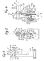
- Figures 7 to 10 show another embodiment of the stringing machine according to the invention.
- the corresponding machine firstly comprises a base 1a of substantially parallelepiped shape. On the upper face 2a of the base, there is a horizontal table 3a which has the shape of a disc, movable in rotation about the axis 4a located in the center thereof.
- These half-cradles are coplanar, and have a rounded ccccave shape facing each other. Their spacing is adjustable so as to adapt to the frame of the racket that has been shown schematically by the broken line 9a, to position it and to immobilize it.
- two hooks 10a and 11a respectively secured to each half-cradle flatten the frame of the racket against them.
- the assembly of the racket, half cradles, arms and discs is movable in rotation about the substantially vertical axis 4a.
- a handle 12a preferably located on the upper face 2a of the base controls a brake which exerts on the disc braking of different intensities. This handle makes it possible to obtain gentle braking, allowing manual rotation of the disc around the axis with reduced effort, and firm immobilization of the disc relative to the base of the machine, during the operation of energizing the hose.
- the hose that is to be tensioned is engaged between the two jaws of an anchoring device 14a secured to a tensioning assembly.
- This assembly comprises a carriage 15a, located inside the base of the machine, controlled in movement by an electric motor also located inside the base.
- the movement of the carriage is a translation which moves the arm 16a, of which the anchoring device 14a is integral, in a slot 17a.
- An electric control 18a allows the starting of the drive motor carriage, stopping and returning to its original position.
- the desired hose tension is displayed on a display button 19a, and the movement away from the anchoring device 14a is stopped when the hose tension reaches the displayed tension.
- the hose tension When the desired hose tension is reached, it should be immobilized temporarily so that it can be manipulated at its end, and put back on again as part of the racket.
- the hose is immobilized from inside the frame. It is then possible to relax the part of the hose located outside the frame, and to handle it.
- a clamp 20a comprising jaws is positioned so that these clamp the hose against the frame of the racket, immobilize it and keep it temporarily under tension.
- two arms 21a and 22a articulated define at their crossing point the positioning of the clamp 20a.
- These arms are free to rotate about vertical axes 23a and 24a, located near the two arms 5a and 6a on which are fixed the two half-cradles which support the racket.
- the two axes 23a and 24a are integrated in the arms 5a and 6a for supporting the half-cradles.
- the length of the arms is slightly less than the distance between the two arms of the support 5a and 6a, so that each of these can be maneuvered over the entire surface of the disc 3a. Their height is slightly different, so that they overlap at their crossing point.
- Each of the two arms has a lumen, respectively 25a and 26a, horizontal, and extending over the greatest length of the arms 21a and 22a.
- the lights At the point of intersection of the two arms, which defines the position of the clamp, the lights define a diamond-shaped orifice.
- the clamp 20a is mounted on an axis which crosses the orifice defined by the crossing of the two lights and which makes it possible to position it.
- the lower arm that is to say in the case of FIG. 7, the arm 21a is kept in its rotational movement by a finger integral with the latter which runs through a groove 27a dug in the disc.
- This groove has a substantially circular shape, centered on the axis of rotation of the arm 21a.
- the finger and the groove are more particularly shown in FIG. 8.
- the finger has a vertical part 28a, and a horizontal part 29a parallel to the direction of the largest dimension of the arm 21a.
- the groove which receives the finger has a section corresponding to the shape of the latter, and the finger has in its upper part a horizontal part 30a which bears on the upper face of the groove. The movement of the rotating arm is however permitted by the circular shape of the groove.
- the movement of the arms around their respective axes makes it possible to move the clamp in a substantially horizontal plane, and to position it at any point defined by the point of intersection of the two slots in each arm.
- Figures 9 and 10 are more particularly related to the clamp, and the mounting thereof on the two arms.
- the clamp has several degrees of freedom, first of all it can move in the horizontal plane by displacement of the two arms, it can also be moved in height as well as in rotation on itself.
- the clamp 20a firstly has two jaws, a fixed jaw 31a, and a movable jaw 32a. Each of these jaws has teeth 33a, located horizontally, in its upper part. The teeth of each of the jaws are respectively opposite one another. Their spacing corresponds to the spacing of the hoses on the racket, so that the teeth can be interposed therebetween.
- the jaws are secured by screwing in their lower part, and the lower end 34a of the movable jaw has been slightly bevelled on its lower face, at the level of its assembly with the fixed jaw. This beveling slightly spreads the movable jaw relative to the fixed jaw, and their respective interior surfaces form a V of small opening inside which the hose 35a can be introduced.
- the clamping of the two jaws is obtained by pulling the movable jaw against the fixed jaw, and by playing on the elasticity of this movable jaw.
- the device which allows the tightening will be described later.
- the assembly of the two jaws can slide vertically along a guide plate 36a. This vertical sliding makes it possible to raise the jaws of the clamp and to engage them on either side of the hose to be immobilized.
- the guide plate 36a has a lumen 40a which opens onto each of the two largest faces of the plate 36a.
- This light has a substantially rectangular shape, and its largest dimension is oriented vertically. Through this light, slides a part 37a of substantially rectangular section and width slightly less than the width of that which passes through the jaw 31a through the hole 39a.
- this part is secured to the movable jaw by means of a screw 38a.
- the part 37a can move vertically along the lumen 40a, causing in its movement the movable jaw and the fixed jaw.
- the length of the light is determined so that in the low position the clamp is below the level of the hoses symbolized by the dashed line 41a, and that in the high position the hose to be immobilized penetrates inside the jaws. It should be noted that in this case any hoses transverse to the hoses to be immobilized are positioned between the teeth 33a of the two jaws.
- the part 37a also comprises a rounded part 41a on which a handle 42a takes hold, the role of which will be described later.
- the assembly formed by the two jaws of the clamp, and the plate 36a is secured by an ax l 43a, around which this assembly can pivot.
- This axis is substantially vertical, and passes through a diamond-shaped orifice defined by the crossing of the two slots 25a and 26a respectively of the two arms.
- the axis of rotation 43a is composed of two parts 45a and 46a assembled by screwing 47a.
- the part 46a comprises at its lower end a head 44a of which the bearing surface is in contact with the lower surface of the lower arm 21 a. At its upper end, this part 46a comprises a thread screwed into a coaxial tapped hole in part 45a, so as to assemble these two parts.
- a washer 48a is interposed on the part 46a of the axis between the two arms. This washer avoids the friction of the two arms one on the other.
- the non-threaded length of the part 46a of the axis corresponds substantially to the height of the two arms, and of the washer 48a.
- the diameter of the non-threaded part is substantially equal to the width of the slots 25a and 26a respectively of the two arms 21a and 22a.
- the upper part 45a of the axis 43a is coaxial with the part 46a, and comprises at its upper end a lug 49a, offset with respect to the axis of the two parts 45a and 46a of the axis of rotation.
- This lug 49a comprises a substantially flat part, located near the axis, on which is fixed, for example by screwing 50a, the support plate 36a. This screwing 50a therefore performs the assembly of the support plate 36a with the axis of rotation 43a.
- the diameter of the upper part 45a of the axis of rotation is slightly greater than the diameter of the unthreaded length of the part 46a.
- a sleeve 51a is mounted in vertical sliding on the part 45a of the axis of rotation 43a.
- This socket has an inside diameter substantially equal to the outside diameter of the part 45a. In its lower part, it has a shoulder 52a which comes to bear on the upper surface of the upper arm 22a.
- This socket laterally has two axes 53a and 54a which are substantially horizontal, diametrically opposite, coaxial and projecting with respect to the vertical exterior surface of the socket 51a.
- a U-shaped stirrup 55a pierced on each of its wings with a substantially horizontal hole with a diameter substantially equal to the diameter of the axes 53a and 54a is articulated in rotation relative to the bushing around these horizontal axes.
- a handle 42a makes it possible to place the clamp in position relative to the hose to be immobilized and to secure it.
- This handle firstly comprises an end of known shape, not shown in FIG. 10 which allows it to be easily manipulated.
- the handle At its other end located on the side of the clamp, the handle has a form of yoke in which the clamp 37a is housed.
- a horizontal axis of articulation crosses the handle right through, and the part 37a, which allows the rotation of the handle relative to this part 37a in a substantially vertical plane.
- a second axis 57a, parallel to the axis 56a crosses the part of the handle which has a form of yoke from side to side.
- a stud 58a is fixed on the second axis 57a, perpendicular thereto, and substantially in the middle. This stud 58a can therefore pivot with the horizontal axis 57a.
- the end 59a of the stud 58a is threaded, and enters a hole 60a drilled in the upper part of the stirrup 55a. This hole 60a is positioned so that the pin 58a can slide freely in it during the movement of the handle.
- a nut 61a screwed onto the threaded part of the stud 58a makes it possible to limit the stroke of the latter in the hole 60a, by resting on the upper face of the stirrup.
- the handle When the handle will be actuated downward, the stud 58a slides in the hole 60a of the stirrup 55a until the nut 61a abuts against the upper bearing face 62a of the stirrup.
- the handle exerts a slight pressure on the sleeve 51a, which by means of its shoulder 52a exerts a slight pinch between the two arms 2la and 22a.
- the handle 42a and the sleeve 51a are articulated relative to each other by the axes on the one hand 57a, and on the other hand 53a and 54a of the sleeve. Following the movement of the handle causes it to pivot relative to the axis 57a, and therefore a rise in the axis 56a.
- This axis drives in its movement the part 37a as well as the two jaws 31a and 32a of the clamp.
- the ascent of the two jaws of the clamp stops when the upper face of the part 37a abuts on the upper end 63a of the lumen 40a.
- the height at which the two jaws of the pliers, as well as the part 37a abut is determined so that the jaws of the pliers, and more particularly its teeth 33a rise to the level of the height 41a, c '' ie at the level of the hose to be immobilized.
- the two axes 56a and 57a pivot relative to each other, the axis 56a exerts an upward traction on the axis 43a, and the axis 57a exerts a thrust on the socket 51a via the stirrup 55a.
- This third part of the movement therefore strongly clamps the two arms 21a and 22a, and immobilizes them relative to one another. Since these arms pivot around axes 23a and 24a integral with the disc 3a, the two arms and the clamp are immobilized relative to the disc.
- the axis 43a around which the clamp can pivot is immobilized by the pinching of the two arms 21a and 22a, since this axis intervenes in the pinching.
- a boss 65a comes into contact with the two zones 66a and 67a of the bearing face 36a, which runs along the lumen 40a. This contacting exerts via the part 37a a traction of the movable jaw towards the fixed jaw, and therefore a closing of the latter on the hose to be immobilized.
- the screw 38a which secures the movable jaw with the part 37a makes it possible to adjust the position of this jaw relative to the axis 56a. It is possible by more or less deep tightening of this screw to adjust the spacing of the movable jaw relative to the fixed jaw, and therefore the pinching of the two jaws on the hose. Depending on the diameter of the hose to be immobilized, it will therefore be possible to adjust this screw in order to adapt the clamp to it.
- the pinching of the two arms 21a and 22a can be adjusted in turn by the nut 61a mounted on the stud 58a. Depending on the position thereof, the stud 58a will penetrate more or less deeply into the hole 60a, and the thrust on the sleeve 51a will be more or less significant.
- the surface of the handle in contact with the two zones 66a and 67a has any suitable shape which gives it a stable locking position at the end of its movement. in the low position.
- the handle 42a in fact controls two different clamps, one formed by the head 44a of the axis 43a and the socket 51a, and the other by the two jaws 31a and 32a of the clamp which immobilizes the hose .
- the two pliers have their respective nip setting, that is to say the nut 61a of the stud 58a for the nip of the two arms, and the screw 38a for the nip of the two jaws.
- the final clamping of the two arms 21a and 22a takes place before the final clamping of the hose by the two jaws 31a and 32a.
- the decomposition of the movements is allowed by the offset position of the two axes 56a and 57a, which are located in an approximately horizontal plane when the handle is unlocked, and which are placed in an approximately vertical plane, one above the other when the handle is locked.
- the clamp is brought under the hose to be immobilized, preferably against the frame of the racket, by moving the two arms 21a and 22a.
- the gripper jaws are then oriented parallel to the hose to be immobilized.
- the two arms tooth the intersection defines the position of the clamp in a horizontal plane are first of all slightly pinched, the jaws of the clamp are raised at the level of the hose to be immobilized, then the two arms are strongly pinched and the jaws are closed. It is naturally enough to unlock the handle by lifting it to release the clamp in its different degrees of freedom.
Landscapes
- Health & Medical Sciences (AREA)
- General Health & Medical Sciences (AREA)
- Physical Education & Sports Medicine (AREA)
- Clamps And Clips (AREA)
- Supports For Pipes And Cables (AREA)
- Tension Adjustment In Filamentary Materials (AREA)
Abstract
L'invention concerne une machine à corder les raquettes. La machine comporte un berceau susceptible d'immobiliser le cadre de la raquette et des moyens de mise en tension d'un boyau; elle est caractérisée en ce que les moyens de mise en tension comportent un chariot extérieur au berceau et comportant des moyens d'ancrage du boyau, par ailleurs solidaire du cadre, des moyens pour guider et déplacer le chariot en translation dans le sens d'un éloignement ou d'un rapprochement par rapport au berceau, pour appliquer une traction au boyau, et des moyens pour comparer à chaque instant la tension instantanée du boyau à une tension prédéterminée à établir, pour autoriser ledit déplacement du chariot dans le sens d'un éloignement tant que la tension instantanée du boyau est inférieure à la tension prédéterminée, et pour immobiliser le chariot quand ces tensions sont égales. Application à la réalisation d'une machine confortable et rapide d'utilisation, avec une précision améliorée.The invention relates to a racket stringing machine. The machine comprises a cradle capable of immobilizing the frame of the racket and means for tensioning a hose; it is characterized in that the tensioning means comprise a carriage external to the cradle and comprising means for anchoring the hose, moreover integral with the frame, means for guiding and moving the carriage in translation in the direction of a distance or approximation with respect to the cradle, to apply traction to the hose, and means for comparing at all times the instantaneous tension of the hose with a predetermined tension to be established, to authorize said movement of the carriage in the direction of away as long as the instantaneous tension of the hose is lower than the predetermined tension, and to immobilize the carriage when these tensions are equal. Application to the production of a machine which is comfortable and quick to use, with improved precision.
Description
La présente invention est relative à une machine à corder les raquettes.The present invention relates to a racket stringing machine.
Actuellement, la plupart du temps, on utilise pour corder les raquettes des machines mettant en oeuvre un poids qu'il faut manipuler, au fur et à mesure du cordage, pour mettre en tension successivement chaque montant et chaque travers.Currently, most of the time, we use machines for stringing rackets using a weight that must be manipulated, as the stringing, to successively tension each amount and each cross.
Cette manipulation est fastidieuse et pénible ; de plus, de telles machines laissent une large part aux facteurs humains, et notamment au tour de main du cordeur, et il n'est pas rare que l'on constate des irrégularités dans la tension des boyaux cordés par leur moyen.This manipulation is tedious and painful; moreover, such machines leave a large part to human factors, and in particular to the knack of the stringer, and it is not rare that irregularities are observed in the tension of the strings strung by their means.
Le but de la présente invention est de proposer une machine à corder remédiant aux inconvénients de ces machines largement répandues.The object of the present invention is to provide a stringing machine overcoming the drawbacks of these widely used machines.
A cet effet, l'invention propose une machine assurant la mise en tension du boyau, au niveau d'un montant ou d'un travers de la raquette, par déplacement linéaire d'un chariot avec lequel est solidarisée l'extrémité libre du boyau, l'autre extrémité de celui-ci étant solidaire du cadre de la raquette ; le déplacement du chariot est avantageusement piloté par des moyens électromécaniques à commande électronique, en fonction d'une comparaison constante entre la tension instantanée du boyau, qui est imposée par le déplacement du chariot, et une tension prédéterminée en fonction des caractéristiques souhaitées de la raquette et du sport à la pratique duquel elle est destinée.To this end, the invention provides a machine ensuring the tensioning of the hose, at an upright or across the racket, by linear movement of a carriage with which the free end of the hose is secured. , the other end of it being secured to the frame of the racket; the movement of the carriage is advantageously controlled by electromechanical means with electronic control, according to a constant comparison between the instantaneous tension of the hose, which is imposed by the movement of the carriage, and a predetermined tension according to the desired characteristics of the racket and the sport for which it is intended.
Une telle machine se révèle naturellement beaucoup plus confortable d'utilisation qu'une machine mettant en oeuvre des poids, et se révèle considérablement plus sensible d'une part du fait qu'elle élimine totalement l'influence des facteurs humains et d'autre part du fait de la possibilité qu'elle offre d'un large recours à l'électronique.Such a machine is naturally much more comfortable to use than a machine using weights, and is considerably more sensitive on the one hand because it completely eliminates the influence of human factors and on the other hand because of the possibility that it offers a wide use of electronics.
Elle offre aussi une possibilité d'assurer avec une grande précision des mises en tension allant de 0 à 30 kg, ces chiffres donnés à titre d'exemple non limitatif correspondant à la gamme des tensions usuelles de l'ensemble des raquettes destinées aux différents sports, de la raquette de Badminton cordée à une tension de 3 à 6 kg à la raquette de tennis cordée à une tension variant généralement de l'ordre de 18 à 22 kg.It also offers a possibility of ensuring with great precision tensioning ranging from 0 to 30 kg, these figures given by way of nonlimiting example corresponding to the range of usual tensions of all rackets intended for different sports. , from the Badminton racket strung at a tension of 3 to 6 kg to the tennis racket strung at a tension generally varying from around 18 to 22 kg.
Compte tenu de cette large plage de réglage possible, un autre but de l'invention est de rendre l'ensemble de la machine adaptable à tous les types de raquettes, quelle que soit leur forme ou leurs dimensions ; à cet effet, dans un mode de mise en oeuvre préféré, l'invention propose des moyens de réglage du berceau inmobilisant à volonté sur la machine la raquette en cours de cordage, ce qui rend la machine selon l'invention réellement universelle.Given this wide range of possible adjustment, another object of the invention is to make the whole machine adaptable to all types of rackets, whatever their shape or their dimensions; for this purpose, in a preferred embodiment, the invention provides means for adjusting the cradle immobilizing at will on the machine the racket during stringing, which makes the machine according to the invention truly universal.
Enfin, comme il ressortira de la description d'un mode de mise en oeuvre préféré, la machine selon l'invention peut être réalisée de façon particulièrement simple et économique, et sous un encombrement réduit, en dépit de ses possibilités bien supérieures en précision et en gamme de réglages possibles à celles des machines actuellement connues.Finally, as will emerge from the description of a preferred embodiment, the machine according to the invention can be produced in a particularly simple and economical manner, and in a small footprint, despite its much greater possibilities in terms of precision and in the range of possible settings to those of currently known machines.
La machine à corder les raquettes selon l'invention, comportant un berceau susceptible d'immobiliser le cadre de la raquette et des moyens de mise en tension d'un boyau immobilisé dans une zone du cadre et libre à coulissement dans une deuxième zone de celui-ci, par traction sur une zone du boyau située au-delà de la deuxième zone par rapport à la première, est caractérisée en ce que les moyens de mise en tension comportent :
- - un chariot extérieur au berceau et portant des moyens d'ancrage de ladite zone du boyau ;
- - des moyens pour guider et déplacer le chariot en translation dans le sens d'un éloignement ou d'un rapprochement par rapport au berceau, pour appliquer une traction au boyau ;
- - des moyens pour comparer à chaque instant la tension instantanée du boyau à une tension prédéterminée à établir, et pour autoriser ledit mouvement dans le sens d'un éloignement tant que la tension instantanée du boyau est inférieure à la tension prédéterminée, et pour inmobiliser le chariot quand la tension instantanée du boyau est égale à la tension prédéterminée.
- - A trolley outside the cradle and carrying means for anchoring said area of the hose;
- - Means for guiding and moving the carriage in translation in the direction of a distance or an approximation relative to the cradle, to apply traction to the hose;
- means for comparing at any instant the instantaneous tension of the hose with a predetermined tension to be established, and for authorizing said movement in the direction of a distance as long as the instantaneous tension of the hose is lower than the predetermined tension, and for immobilizing the carriage when the instantaneous tension of the hose is equal to the predetermined tension.
Dans une forme de réalisation avantageuse, la présente machine est également conçue pour pouvoir déplacer la pince, et la mettre en position par rapport au boyau à immobiliser provisoirement sur l'ensemble de la surface définie par le cadre de la raquette. Dans cette forme de réalisation, il est également possible de positionner la pince à l'extérieur de cette surface, ce qui permet l'utilisation de la machine à corder pour des raquettes de dimensions plus grandes que celles utilisées actuellement.In an advantageous embodiment, the present machine is also designed to be able to move the clamp, and put it in position relative to the hose to be immobilized temporarily over the entire surface defined by the frame of the racket. In this embodiment, it is also possible to position the clamp outside this surface, which allows the use of the stringing machine for rackets of larger dimensions than those currently used.
La machine à corder selon cette forme de réalisation avantageuse est caractérisée par le fait que lesdits moyens pour immobiliser provisoirement le boyau sous tension comprennent deux bras sensiblement horizontaux, mobiles en rotation autour d'axes verticaux diamétralement opposés par rapport au disque, situés à des hauteurs voisines, de longueur inférieure à la distance entre les deux axes, dont le point de croisement décrit au moins toute la surface inférieure du cadre cela raquette.The stringing machine according to this advantageous embodiment is characterized in that the said means for temporarily immobilizing the hose under tension comprise two substantially horizontal arms, movable in rotation around vertical axes diametrically opposite with respect to the disc, located at heights neighboring, of length less than the distance between the two axes, the crossing point of which describes at least the entire lower surface of the frame that racket.
L'invention sera mieux comprise si l'on se réfère à la description ci-dessous, ainsi qu'aux dessins annexés qui font partie intégrante de cette description.The invention will be better understood if reference is made to the description below, as well as to the accompanying drawings which form an integral part of this description.
- La figure 1 est une vue d'ensemble, en perspective, d'une machine selon l'invention ;Figure 1 is an overall perspective view of a machine according to the invention;
- La figure 2 montre une vue de dessous de cette machine ;Figure 2 shows a bottom view of this machine;
- La figure 3 montre une vue de détail d'un bras reliant à la table d'orientation de la raquette à corder l'un des deux demi-berceaux réglables recevant celle-ci ;Figure 3 shows a detail view of an arm connecting to the orientation table of the racket to string one of the two adjustable half-cradles receiving it;
- La figure 4 montre l'ensemble des moyens de comparaison de la tension instantanée du boyau à une tension prédéterminée et de réglage de cette tension prédéterminée, vu suivant une direction et dans un sens correspondant à la direction et au sens de déplacement de ces éléments correspondant à la mise en tension croissante du boyau ;FIG. 4 shows all of the means for comparing the instantaneous tension of the hose with a predetermined tension and for adjusting this predetermined tension, seen in a direction and in a direction corresponding to the direction and the direction of movement of these corresponding elements. the increasing tensioning of the hose;
- La figure 5 montre une vue en coupe dans un plan V-Vde la figure 4 ;Figure 5 shows a sectional view in a plane V-V of Figure 4;
- La figure 6 montre une vue en perspective des moyens de réglage de la tension prédéterminée à établir dans le boyau ;FIG. 6 shows a perspective view of the means for adjusting the predetermined tension to be established in the hose;
- La figure 7 est une vue en perspective d'une autre forme de réalisation de la machine à corder selon la présente invention ;Figure 7 is a perspective view of another embodiment of the stringing machine according to the present invention;
- La figure 8 est une vue partielle en coupe d'un détail de la figure 7 ;Figure 8 is a partial sectional view of a detail of Figure 7;
- La figure 9 est une vue en coupe partielle de face du dispositif prévu dans cette machine pour l'imobilisation du boyau sous tension ;Figure 9 is a partial sectional front view of the device provided in this machine for immobilizing the hose under tension;
- La figure 10 est une vue de côté selon la coupe X-X de la figure 9.FIG. 10 is a side view along the section X-X of FIG. 9.
Les différentes figures 1 à 6 correspondent à un état de repos de la machine, c'est-à-dire à un état préalable à la mise en tension d'un tronçon de boyau correspondant à un montant ou à un travers de la raquette.The different FIGS. 1 to 6 correspond to a state of rest of the machine, that is to say to a state prior to the tensioning of a section of hose corresponding to an upright or across the racket.
A la figure 1, on a schématisé en trait mixte une raquette 1 et en trait discontinu un boyau 2, dont, par exeirple, la machine selon l'invention est prête à mettre en tension un tronçon correspondant à un montant.In Figure 1, there is shown schematically in broken line a racket 1 and in broken line a
Pour recevoir et immobiliser la raquette 1, la machine comporte des moyens 3 réglables d'une part afin de s'adapter à toutes les formes et dimensions de raquette, et permettre ainsi d'exploiter au mieux les larges possibilités du système de mise en tension qui sera décrit plus loin, et d'autre part afin de permettre l'orientation de la raquette 1 en fonction de la position du montant ou du travers à mettre en tension.To receive and immobilize the racket 1, the machine comprises means 3 adjustable on the one hand in order to adapt to all the shapes and dimensions of racket, and thus make it possible to make the best use of the wide possibilities of the tensioning system. which will be described later, and on the other hand to allow the orientation of the racket 1 as a function of the position of the upright or the cross to be tensioned.
A cet effet, les moyens 3 conportent, sur la face supérieure horizontale 5 du socle 6 de la machine, une table horizcntale 4 intégralement de révolution autour d'un axe 7 fixe par rapport au socle 6, sur lequel la table 4 est montée à rotation libre autour de cet axe 7.To this end, the means 3 include, on the horizontal upper face 5 of the base 6 of the machine, a horizontal table 4 completely of revolution around an axis 7 fixed relative to the base 6, on which the table 4 is mounted at free rotation around this axis 7.
Dans l'exemple illustré, la table 4 présente la forme d'un disque, dont la face supérieure 8 est.plane et dont la face inférieure 9 porte, en retrait vers l'axe 7 par rapport à sa périphérie circulaire 10, une jupe continue 11, intérieurement et extérieurement cylindrique de révolution autour de l'axe 7.In the example illustrated, the table 4 has the shape of a disc, the upper face 8 est.plane and whose lower face 9 carries, set back towards the axis 7 relative to its
Dans des positions diamétralement opposées, la périphérie extérieure cylindrique de la jupe 11 porte deux bras identiques, respectivement 12 et 13, pour l'essentiel verticaux et formant au-dessus de la face supérieure 8 de la table 4 une saillie de hauteur identique, pour les raisons qui apparaîtront plus loin, chacun des bras 12 et 13 est relié à la périphérie extérieure cylindrique de la jupe 11 par un rebord horizontal, radial, tel que 14, qui d'une part maintient le bras à distance de la périphérie 10 et d'autre part, se situant à distance de la face 9, dégage également la zone de celle-ci située entre la périphérie extérieure cylindrique de la jupe 11 et la périphérie 10.In diametrically opposite positions, the cylindrical outer periphery of the
A sa partie supérieure, à un niveau identique par rapport à la face 8 de la table 4, chacun des bras 12 et 13 porte un demi-berceau en forme de croissant horizontal, respectivement 15 et 16, les deux demi-berceaux 15 et 16 dont les concavités se font face reprennent sensiblement la forme de deux zones opposées du cadre d'une raquette de façon à pouvoir porter un tel cadre par lesdites zones de celui-ci.At its upper part, at an identical level with respect to the face 8 of the table 4, each of the
A cet effet, les deux demi-berceaux 15 et 16 présentent des faces supérieures horizontales coplanaires, respectivement 17 et 18, et chacun présente une pluralité d'orifices verticaux, respectivement 19 et 20, répartis sur sa face supérieure pour permettre le montage sur celle-ci, dans les positions les plus appropriées compte tenu de la forme et des dimensions du cadre d'une raquette à corder, de vérins horizontaux, tels que respectivement 21 et 22, propres à prendre appui sur la périphérie extérieure du cadre de la raquette pour immobiliser celle-ci sur l'ensemble constitué par les demi-berceaux 15 et 16 ; en outre, en vue de cette immobilisation est prévu dans la concavité de chaque demi-berceau, dans des positions diamétralement opposées conpte tenu de l'axe 7 et en saillie au-dessus des faces 17 et 18, un crochet, respectivement 23 et 24, propre à s'appuyer de façon centrifuge sur la périphérie intérieure du cadre de la raquette ; à cet effet, chacun des crochets 23 et 24 est réglable selon une direction radiale, par rapport au demi-berceau correspondant, au moyen d'un bouton molleté, respectivement 25 et 26.To this end, the two half-
Pour permettre une adaptation de la machine à des cadres de raquettes présentant des dimensions très différentes, les deux demi-berceaux 15 et 16 sont en outre montés sur les extrémités supérieures des bras 12 et 13, respectivement par l'intermédiaire de moyens autorisant leur réglage en position suivant une même direction radiale, horizontale.To allow adaptation of the machine to snowshoe frames having very different dimensions, the two half-
On se référera à ce sujet plus particulièrement à la figure 3, qui illustre le bras 12 auquel le bras 13 est identique.Reference will be made to this subject more particularly in FIG. 3, which illustrates the
La figure 3 montre une vue du bras 12 suivant une direction radiale, vers l'axe 7 ; il y apparaît que le bras 12 présente vers le haut une face supérieure plane, horizontale 27 à l'intérieur de laquelle est aménagée une rainure en queue d'aronde 28, horizontale, orientée radialement ; complémntairement, le demi-berceau 15 présente une face inférieure plane, horizontale 29, propre à reposer par l'une de ses zones sur la face supérieure 27 du bras 12, et une nervure 30 orientée radialement, horizontalement, et formant sous la face 29 une saillie dont le profil en queue d'aronde est complémentaire de celui de la rainure 28 ; à l'intérieur de cette nervure 30 est aménagé un canal 31 à l'intérieur duquel peut coulisser une tige 32 solidaire de l'ergot 23 dans la concavité du demi-berceau 15 et portant au niveau de la convexité de celui-ci le bouton molleté 25, apte à se visser plus ou moins sur la tige 32, par rotation, pour régler la position de l'ergot 23 par rapport au demi-berceau 15.FIG. 3 shows a view of the
Ainsi, le demi-berceau 15 peut coulisser suivant une direction horizontale, radiale, sur la face supérieure horizontale 27 du bras 12, pour permettre une immobilisation dans une position adaptée au mieux à la forme et aux dimensions du cadre de la raquette à corder, le bras 12 est conçu comme une pince et présente à cet effet une fente verticale 33 le traversant de part en part suivant un plan incluant l'axe 7 et l'axe du fend de la rainure 28, la fente 33 prenant naissance au fond de cette rainure et s'étendant sur la majeure partie de la hauteur du bras 12 ; cette fente 33 définit à la partie supérieure du bras 12 deux mâchoires, respectivement 34 et 35, dont chacune correspond à l'un des flancs de la rainure 28 ; l'immobilisation à volonté de la nervure 30 dans la rainure 28 est assurée par serrage des deux mâchoires 34 et 35, au moyen d'une vis les traversant de part en part selon une direction 36 perpendiculaire au plan moyen de la fente 33 (cette vis n'a pas été représentée) ; on notera que, étant donné la forme en queue d'arcnde de la rainure 28 et de la nervure 30, le serrage de la mâchoire 34 s'accompagne d'un pla- çage de la face inférieure 29 du demi-berceau 15 sur la face supérieure 27 du bras 12, ce qui assure un niveau constant de la face supérieure 17 du demi-berceau 15 par rapport à la table 4 quel que soit le réglage adopté ; des moyens analogues étant adoptés pour assurer le réglage du demi-berceau 16 suivant une direction radiale à la partie supérieure du bras 13, on est ainsi assuré d'une coplanéarité constante des faces supérieures respectives 17 et 18 des deux demi-berceaux 15 et 16, quel que soit leur réglage ; en d'autres termnes, quelles que soient sa forme et ses dimensions, une raquette 1 est toujours immobilisée à un même niveau sur la machine, et la rotation de la table 4 autour de l'axe 7 s'accompagne d'un déplacement de la raquette suivant son plan moyen qui reste quant à lui fixe en position.Thus, the half-
Approximativement à ce niveau, la machine comporte dans une zone toujours située à l'extérieur du berceau constitué par les deux demi-berceaux 15 et 16, c'est-à-dire hors de l'aplomb de la table 4, des moyens d'ancrage 37 pour le boyau, lesquels sont portés par un ensemble 38 de mise en tension de ce boyau qui sera décrit plus loin.At approximately this level, the machine comprises, in a zone always situated outside the cradle constituted by the two half-
Une rotation de la table 4 autour de son axe 7 permet de présenter successivement la raquette dans les positions, vis-à-vis des moyens d'ancrage 37 et de l'ensemble de mise en tension 38, les plus appropriés pour le cordage successif respectivement de chaque montant et de chaque traverse ; la position la plus appropriée au cordage d'un montant ou d'une traverse correspond à une position où le tronçon de boyau à mettre en tension est immobilisé dans une première zone du cadre de la raquette, libre à coulissement par rapport à une deuxième zone de celle-ci, et solidarisé de façon provisoire avec les moyens d'ancrage 37 au-delà de cette deuxième zone par rapport à la première, avec une forme aussi proche de la forme rectiligne que possible.A rotation of the table 4 around its axis 7 makes it possible to present the racket successively in the positions, vis-à-vis the anchoring means 37 and the
Pour permettre l'immobilisation de la table 4 successivement dans les différentes positions les plus appropriées sont prévus, à l'intérieur du socle 6, des moyens de freinage 39 qui vont être décrits à présent plus particulièrement en référence à la figure 2.In order to allow the table 4 to be immobilized successively in the various most suitable positions, there are provided, inside the base 6,
Ces moyens de freinage 39 sont commandés manuellement par une poignée 40 située au-dessus de la face 5 du socle 6 et mobile à rotation autour d'un axe vertical par rapport à celui-ci, entre trois positions crantées correspondant respectivement à une totale liberté de la table 4 à rotation autour de l'axe 7, à une position de freinage doux autorisant une rotation manuelle de la table 4 autour de l'axe 7 moyennant un effort réduit, pour des raisons de commodité de travail, et une position d'immobilisation ferme de la table 4 par rapport au socle 6, pendant une opération de mise en tension.These braking means 39 are manually controlled by a
Les moyens de freinage 39 sont illustrés à la figure 2 dans la première de ces trois positions.The
Dans l'exemple illustré, les moyens de freinage 39 comportent un levier horizontal 42 articulé à l'une de ses extrémités autour d'un axe vertical 41 fixe par rapport au socle 6 de la machine et disposé par rapport à l'axe 7 de telle façon que, dans ses trois positions correspondant aux trois positions crantées de la poignée 40, le levier 42 soit orienté suivant une corde de la périphérie intérieure cylindrique de la jupe 11 de la table 4, à un niveau légèrement inférieure au niveau inférieur de cette jupe.In the example illustrated, the braking means 39 comprise a
A sa deuxième extrémité, incurvée vers le haut et traversant la paroi supérieure horizontale 44 du socle 6 via une lumière 45 de celle-ci, le levier 42 porte un patin 43 placé en regard de la périphérie intérieure cylindrique de la jupe 11 ; l'application du patin 43 contre cette périphérie intérieure se traduit, en fonction de la pression avec laquelle elle s'effectue, par un freinage doux ou énergique de la table 4.At its second end, curved upwards and passing through the horizontal
Entre ses deux extrémités, le levier 42 porte d'une part un point d'ancrage 45bpour une extrémité d'un ressort à boudin 46 dont l'autre extrémité est reliée à un point 47 fixe par rapport au socle 6, dans une position telle que ce ressort 46 applique au levier 42 une traction élastique constante tendant à le faire pivoter autour de l'axe 41 dans le sens d'une application du patin 43 contre la périphérie intérieure cylindrique de la jupe 11 de la table 4, et d'autre part un ergot vertical 48 engagé dans une lumière oblongue 49 d'une biellette horizontale 50 de liaison entre le levier 42 et une came 51 solidaire en rotation de la poignée 40 autour d'un axe vertical 52, à l'intérieur du socle 6 ; la biellette 50 est articulée sur cette came 51, à l'une de ses extrémités, opposée à son extrémité portant la lumière 49, autour d'un axe vertical 53 excentré par' rapport à l'axe 52.Between its two ends, the
Ces éléments sont positionnés de telle façon que la biellette 50, de forme rectiligne, soit orientée transversalement par rapport à la direction générale du levier 42 quelle que soit la position de la came 41 et la position correspondante du levier 42.These elements are positioned in such a way that the
Dans l'exemple illustré, la came 51 est située du même côté du levier 42 que la zone de la périphérie intérieure cylindrique de la jupe 11 contre laquelle doit s'appliquer le patin 43, vis-à-vis de ce patin 43, et le fonctionnement des moyens de freinage 39- est le suivant.In the example illustrated, the
Dans la position illustrée, qui correspond à la liberté de rotation de la table 4 autour de son axe 7, l'axe 53 est situé entre l'axe 52 et le levier 42 et la biellette 50 applique à l'ergot 48, alors en contact avec l'extrémité de la lumière 49 la plus proche de l'axe 53, une poussée maintenant le patin 43 à distance de la périphérie intérieure cylindrique de la jupe 11 ; à cette première position correspond l'engagement, dans une première encoche 54 de la périphérie par ailleurs circulaire de la came 51, d'un galet 55 que des moyens appropriés tendent à rapprocher élastiquerrent de l'axe 52, centre la périphérie de la came 51.In the illustrated position, which corresponds to the freedom of rotation of the table 4 around its axis 7, the
Dans une deuxième position des moyens de freinage 39, correspondant à une rotation de la poignée 40 et de la came 51 dans le sens de la flèche 56 de la figure 2, laquelle amène le galet 55 dans un deuxième crantage 57 de la périphérie de la came 51, l'ergot 48 occupe une position intermédiaire entre les deux extrémités de la lumière oblongue 49 de la biellette 50, cette lumière étant orientée suivant la direction générale de la biellette, et le ressort 46 applique le patin 43 élastiquement contre la périphérie intérieure cylindrique de la jupe 11 de la table 4 ; cette position correspond à un freinage doux de la table 4.In a second position of the braking means 39, corresponding to a rotation of the
Enfin, dans une troisième position correspondant à la poursuite de la rotation de la poignée 40 et de la came 51 dans le sens de la flèche 56 autour de l'axe 52, le galet 55 s'engage dans un troisième crantage 58 de la périphérie de la came 51 et l'ergot 48 est en contact avec l'extrémité de la lumière 49 la plus éloignée de l'axe 53, la biellette 50-appliquant au levier 42 une traction se traduisant par une application ferme du patin 43 contre la périphérie intérieure cylindrique de la jupe 11 de la table 4, ce qui se traduit par l'immobilisation totale de celle-ci en rotation autour de son axe 7.Finally, in a third position corresponding to the continued rotation of the
Des moyens appropriés 59 sont prévus pour permettre un réglage de la longueur de la biellette 50 de telle sorte qu'à chacune des trois positions crantées de la came 51 corresponde effectivement l'une des positions du patin 43 définies ci-dessus ; on a schématisé par unoflèche 60, à la figure 2, le mouvement du patin 43 accompagnant la rotation de la came 51 dans le sens de la flèche 56.
Naturellement, on pourrait envisager d'autres modes de réalisation des moyens de freinage de la table 4 sans sortir pour autant du cadre de l'invention, de même que l'on pourrait prévoir une adaptation de celle-ci aux différentes formes et dimensions de raquettes par des moyens autres que ceux qui ont été décrits.Naturally, one could envisage other embodiments of the braking means of the table 4 without departing from the scope of the invention, just as one could provide for an adaptation of the latter to the different shapes and dimensions of snowshoes by means other than those described.
Outre les moyens de freinage 39, la figure 2 montre des moyens préférés pour imprimer aux moyens d'ancrage 37, conformément à l'invention, un mouvement de translation sensiblement parallèlement au plan moyen de la raquette immobilisée sur les deux demi-berceaux 15 et 16, ce mouvement se traduisant par la mise en tension d'un tronçon du boyau.In addition to the braking means 39, FIG. 2 shows preferred means for imparting to the
Selon le mode de réalisation particulièrement simple illustré, ces moyens comportent un moteur électrique 62, dont l'arbre de sortie est en prise, le cas échéant par l'intermédiaire d'un jeu de pignons réducteurs 63, avec une vis 64 qu'il entraîne en rotation, à volonté dans un sens ou dans l'autre, autour de son axe horizontal 65 orienté suivant la direction de translation des moyens d'ancrage 37 souhaitée (cette direction est celle de la flèche 66 de la figure 1 et de la flèche 67 de la figure 2, ces flèches indiquant le sens de translation des moyens d'ancrage 37 correspondant à un accroissement de la tension du boyau).According to the particularly simple embodiment illustrated, these means comprise an
Le filet de la vis 64 est en prise avec un écrou 68 quant à lui fixe en rotation par rapport au socle 6 de la machine, de telle sorte que la rotation de la vis 64 respectivement dans un sens ou dans l'autre se traduise par une translation de l'écrou 68 parallèlement à l'axe 65, respectivement dans un sens ou dans l'autre.The thread of the
Cet écrou 68 est solidaire d'un chariot 69 guidé en translation parallèlement à l'axe 65 par rapport au socle 6, par exemple au moyen de deux glissières rectilignes, fixes, 70 et 71 parallèles à cet axe 65 ; les glissières 70 et 71 sont par exemple définies par des tringles rectilignes autour desquelles glissent des manchons complémentaires du chariot 69, lesquels sont avantageusement garnis intérieurement de tout matériau améliorant le glissement.This
Vers le haut, le chariot 69 porte de façon solidaire un carter 72 portant lui-même des moyens d'ancrage 37 ; ce carter 72 traverse la paroi supérieure 44 du socle 6 via une lumière 73 oblongue selcn une direction parallèle à celle de l'axe 65, de façon à autoriser le déplacement de l'ensemble formé par le chariot 69 et le carter 72 suivant cette direction consécutivement à la rotation de la vis 64 ; avantageusement, la zone de la lumière 73 dégagée lorsque le carter 72 occupe une position déterminée est occultée par un volet coulissant le long de la paroi 44 solidairement avec le chariot 69.Upwards, the
Le carter 72 a pour double rôle de transmettre le mouvement de translation du chariot 69 aux moyens d'ancrage 37, et de protéger les moyens de comparaison de la tension instantanée du boyau à une tension prédéterminée réglable.The
Ces moyens vont être décrits à présent plus particulièrement en référence aux figures 4 à 6.These means will now be described more particularly with reference to FIGS. 4 to 6.
Dans l'exemple illustré, le carter 72 comporte deux joues verticales 74 et 75, parallèles entre elles et parallèles à la direction de déplacement du chariot 69 dont elles sont directement solidaires à travers la lumière 73, et un couvercle 76 oté aux figures 4 et 5.In the example illustrated, the
A leur partie supérieure, les deux joues 74 et 75 portent des paliers, respectivement 78 et 79, définissant un axe de rotation 77, horizontal et situé dans un plan perpendiculaire à la direction de déplacement du chariot 69, pour un arbre 80 pour l'essentiel cylindrique de révolution autour de cet axe 77.At their upper part, the two
Cet arbre 80 traverse la joue 74 de part en part, et porte dans sa zone située hors de l'intervalle entre les deux joues les moyens 37 d'ancrage pour le boyau.This
Ces moyens 37 sent conçus de telle sorte que la mise en tension du boyau par translation de l'ensemble 38 dans le sens de la flèche 66 tende, par réaction, à faire pivoter l'ensemble solidaire formé par ces moyens 37 et l'arbre 80 autour de l'axe 77, par rapport aux joues 74 et 75, dans le sens de la flèche 81 de la figure 5.These means 37 are designed such that the tensioning of the hose by translation of the
Par exemple, les moyens 37 sont constitués par une pince auto-serrante comportant une mâchoire 82 solidaire de l'axe 80 et une mâchoire 83 articulée sur la mâchoire 82, ces deux mâchoires définissant conjointement une périphérie 84 légèrement tronconique de révolution autour de l'axe 77 pour r cevoir le boyau à enroulement et, entre elles, une fente 85 apte à recevoir un brin du boyau et à l'immobiliser par pincement, du fait que l'enroulement sur la périphérie 84 se traduit par un serrage des mâchoires.For example, the
Le long de sa génératrice supérieure, qui correspond à une zone de la mâchoire 82, la périphérie 84 porte deux tétons voisins 86 définissant entre eux une position précise de la zone du boyau 2 enroulée autour de la périphérie 84 pour assurer le serrage de la pince.Along its upper generatrix, which corresponds to an area of the
Entre les joues 74 et 75, ici dans sa zone la plus proche de la première de ces joues, l'arbre 80 porte vers le bas un méplat 87 contre lequel est solidarisée une extrémité 88 aplatie d'un ressort spiral 89, décrivant au mins une portion de spire autour de la périphérie cylindrique de l'arbre 80 et comportant une deuxième extrémité plate 90 en butée contre la périphérie d'un galet 91 monté en rotation libre, autour de son axe 92, parallèle à l'axe 77, sur la" joue 74 ; le ressort 89, le méplat 87 et le galet 91 sont disposés de telle sorte que le ressort tende à appliquer à l'arbre 80 un rappel élastique en sens inverse du sens de la flèche 81 lorsque la mise em tension du boyau par déplacement de l'ensemble 38 dans le sens de la flèche 66 tend à provoquer une rotation conjointe des moyens d'ancrage 37 et de l'arbre 80 dans le sens de cette flèche 81.Between the
Ainsi, il s'établit à chaque instant de la mise en tension du boyau, entre l'effet de la tension instantanée de celui-ci et la réaction élastique du ressort spiral 89, un équilibre se traduisant par une rotation plus ou moins grande de l'arbre 80 dans le sens de la flèche 81, la valeur instantanée de cette rotation témoignant de la valeur instantanée de la tension du boyau.Thus, it is established at each instant of the tensioning of the hose, between the effect of the instantaneous tension of the latter and the elastic reaction of the
Des moyens autres qu'un ressort spiral 89 pourraient être utilisés pour imposer à l'arbre 80 une réaction à l'action du boyau mis sous tension, mais on notera qu'un ressort spiral tel que 89 présente l'avantage de se déformer linéairement en fonction d'un couple de rotation d'axe 77 qui lui est imposé, ce qui signifie en d'autres termes, puisque l'effet de la tension du boyau et celui du ressort spiral 89 s'équilibre à chaque instant, que la valeur instantanée de la rotation des moyens d'ancrage 37 autour de l'axe 77 par rapport à une position correspondant à une tension nulle du boyau et à une tension nulle du ressort spiral 89 est une fonction linéaire de la valeur instantanée de la tension du boyau, ce qui facilite l'affichage de la tension prédéterminée à établir dans celui-ci, comme il sera décrit plus loin.Means other than a
Pour limiter la valeur de la rotation des moyens d'ancrage 37 et de l'arbre 80 autour de leur axe commun 77 sont prévues, sur la joue 75, deux butées respectivement 93 vers l'amont compte tenu du sens de la flèche 81 et 94 vers l'aval conpte tenu de ce sens, complémentairement, l'arbre 80 porte de façon solidaire, vers le bas, à proximité de la joue 75, un organe 95 dont un bord 96, orienté vers l'amont compte tenu du sens de la flèche 81, vient s'appliquer contre la butée 93 lorsque la tension du ressort est nulle, et dont un deuxième bord 97, orienté vers l'aval compte tenu du sens de la flèche 81, vient s'appliquer contre la butée 94 lorsque la tension du ressort spiral 89 est maximale, ce qui correspond à un maxinum de tension applicable à un boyau au moyen de la machine selon l'invention, c'est-à-dire par exemple à un effort de trente kilos.To limit the value of the rotation of the anchoring means 37 and the
On notera que le débattement angulaire possible de l'arbre 80 et des organes qu'il porte de façon solidaire entre les butées 93 et 94 est faible, par exemple de l'ordre de quarante degrés, et des moyens sont prévus pour amplifier de façon linéaire la rotation de l'arbre 80 afin d'en fournir une image significative et en outre d'offrir des possibilités de réglage plus précis de la tension du boyau, dont témoigne la rotation de l'arbre 80.It will be noted that the possible angular movement of the
A cet effet, l'organe 95 est partiellement délimité, à sa partie inférieure, par un bord 98 de révolution autour de l'axe 77 et portant une denture d'engrenage, oomplémentaire de celle d'un pignon 99 monté à rotation sur la joue 75 autour d'un axe 100 parallèle à l'axe 77 ; la démultiplication entre l'organe 95 et le pignon 99 est importante, de telle façon que la rotation de l'organe 95 entre les deux butées 93 et 94 se traduise par une rotation du pignon 99 autour de l'axe 100 sur un angle aussi proche que possible de trois cent soixante degrés, dans un sens indiqué par la flèche 101 de la figure 5 lorsque l'arbre 80 tourne dans le sens de la flèche 81, l'organe 95 tournant naturellement dans le même sens que l'arbre 80 comme l'indique la flèche 102 de la figure 5.To this end, the
A son extrémité la plus éloignée de la joue 75, approximativement à mi-distance des joues 74 et 75, le pignon 99 porte de façon solidaire un bras radial 103 dont le rayon est aussi grand que possible compte tenu de ses possibilités de rotation à l'intérieur du couvercle 76 de l'ensemble 38.At its end furthest from the
A son extrémité la plus éloignée du pignon 99, ce bras 103 porte vers la joue 74 un rebord 104 parallèle à l'axe 100 et, à l'ex- témité de ce rebord 104 la plus proche de la joue 74, c'est-à-dire entre le bras 103 et cette joue 74, une plaquette 105 en retour vers l'axe 100, parallèlement au bras 103 ; cette plaquette 105 constitue un drapeau témoignant de la position instantanée du bras 103 en rotation autour de l'axe 100, c'est-à-dire de la position instantanée de l'arbre 80 autour de l'axe 77, c'est-à-dire également la tension instantanée du boyau 2.At its end furthest from the
Divers moyens peuvent être prévus pour détecter cette position instantanée de la plaquette 105, comme par exemple des détecteurs de proximité opto-électroniques, un jeu de deux bobines d'induction haute fréquence disposées de part et d'autre du passage obligé de la plaquette 105 lorsque le bras 103 tourne autour de l'axe 100, la plaquette 105 ou d'autres moyens équivalents étant alors conçus de la façon la plus appropriée en fonction de ces moyens de détection.Various means can be provided for detecting this instantaneous position of the
Dans l'exenple illustré où, comme il apparaîtra plus loin, on pratique une détection de la position instantanée de la plaquette 105 par rupture d'un champ magnétique, cette plaquette 105 est réalisée en un matériau apte à constituer un écran magnétique, c'est-à-dire en fer doux, le bras 103 étant quant à lui réalisé en un matériau amagnétique.In the illustrated example where, as will appear below, a detection of the instantaneous position of the
Les moyens de détection de la position de la plaquette 105 et de réglage de la tension prédéterminée à établir dans le boyau vont à présent être décrits plus particulièrement en référence aux figures 4 et 6.The means for detecting the position of the
Ces moyens sont portés par la joue 74, sur laquelle ils sont montés à rotation autour d'un axe horizontal 106 coïncidant avec l'axe 100.These means are carried by the
A cet effet, la joue 74 est traversée de part en part par un anbre 108 pour l'essentiel cylindrique de révolution autour de l'axe 106, et comporte pour faciliter la rotation de cet arbre 108 autour de l'axe 106 un palier 107.To this end, the
A l'extérieur de l'espace séparant les joues 74 et 75, l'arbre 108 porte de façon solidaire un bouton gradué 109 permettant d'afficher, face à un repère 110 apposé sur la joue 74, la tension que l'on désire imposer au boyau (voir également la figure 1).Outside the space separating the
La position du bouton 109 illustrée aux figures 4 à 6 correspond à l'affichage d'une valeur nulle de cette tension.The position of the
Entre les deux joues 74 et 75, l'arbre 108 porte par ailleurs de façon solidaire un disque radial 111, situé entre la joue 74 et le passage obligé de la plaquette 105 lors de sa rotation autour de l'axe 100, les rayons respectifs du disque 111 autour de l'axe 106 et du bras 103 autour de l'axe 100 étant sensiblement voisins.Between the two
A proximité de sa périphérie, en regard du passage obligé de la plaquette 105 lors de sa rotation autour de l'axe 100 et dans une position en regard de cette plaquette 105 lorsque la tension prédéterminée affichée au moyen du bouton 109 est nulle et lorsque la tension du boyau l'est également, c'est-à-dire lorsque l'organe 95 est au contact de la hutée 93 (position illustrée), le disque 111 porte un interrupteur à lame souple 112 pilotant le fonctionnement du moteur 62, en fermant le circuit d'alimentation de celui-ci en électricité lorsqu'il est soumis à l'action d'un champ magnétique appliqué en regard de la face du disque 111 sur laquelle il est fixé, pour provoquer le fonctionnement du moteur 62 dans le sens d'un entraînement du chariot 68 dans le sens de la flèche 67, et pour ouvrir ce circuit et arrêter aussi instantanément que possible le moteur 62 lorsque l'action du champ magnétique cesse.Near its periphery, facing the obligatory passage of the
Ce champ magnétique est appliqué à l'interrupteur à lame souple 112, lorsque la plaquette 105 n'est pas située en regard de celui-ci, par un aimant permanent 113 porté par un bras 114 radial par rapport à l'axe 106, et situé entre les passages obligés respectifs de la plaquette 105 et du bras 103 lors de la rotation de ce dernier autour de l'axe 100.This magnetic field is applied to the
Le bras 114 est monté à rotation autour de l'axe 106 par rapport à l'arbre 108, mais il est rappelé élastiquement par un ressort 115, en sens inverse du sens d'une flèche 116 correspondant à la rotation de l'ensemble solidaire disque 111-bouton 109 dans le sens d'un affichage de tension croissante, cette flèche 116 étant dans le même sens que la flèche 101, contre une butée 117 réglable de façon que, lorsque le bras 114 est au contact de cette butée 117 sous l'action du ressort 115, l'aimant 113 soit placé directement en regard de l'interrupteur à lame souple 112.The
Ainsi, la mise en tension d'un troncon du boyau 2 correspondant par exemple à un montant, comme il est illustré à la figure 1, s'effectue de la façon suivante, le boyau étant solidaire du cadre de la raquette dans sa zone la plus éloignée des moyens d'ancrage 37, suivant les cas de façon définitive par exemple par nouage ou de façon provisoire au moyen d'une pince volante ou d'une pince 118 intégrée à la machine comme il sera décrit plus loin, et libre de coulisser par rapport au cadre de la raquette dans sa zone la plus proche des moyens d'ancrage 37.Thus, the tensioning of a section of the
Dans un premier temps, le moteur 62 étant à l'arrêt dans une position de la vis 64 où le chariot 69 de l'ensemble 38 de mise en tension est au plus près de la table 4, on fixe sur les moyens d'ancrage 37 une zone du boyau située à l'extérieur du cadre de la raquette, dans l'exemple illustré en enroulant cette zone sur quelques tours autour de la périphérie 84 des moyens d'ancrage 37 puis en engageant une zone du boyau voisine de sa zone enroulée entre les deux mâchoires 82 et 83 où elle se trouve immobilisée par serrage du fait de l'enroulement.Initially, the
Cn affiche alors au moyen du bouton 109 la tension à appliquer au troncon du boyau envisagé, dans le cas de l'exemple préféré, illustré par rotation du bouton 109 dans le sens de la flèche 116 selon un angle proportionnel à la tension à établir, par rapport à la position de ce bouton correspondant à l'affichage d'une tension nulle.Cn then displays by means of the
Ceci a pour effet de déplacer du même angle, conjointement, l'interrupteur à lame souple 112 et l'aimant 113 qui, initialement, séparés par la plaquette 105 du fait de la tension nulle du boyau, se trouvent dégagés de cette plaquette 105, l'aimant 113 provoquant alors la fermeture de l'interrupteur à lame souple 112 dans le circuit d'alimentation du moteur 62 en électricité.This has the effect of moving the
L'opérateur met alors en route le moteur 62, par fermeture d'un interrupteur 130 également intercalé dans le circuit d'alimentation de celui-ci, pour provoquer un déplacement du chariot 69 dans le sens de la flèche 67, et conjointement un déplacement de l'ensemble de mise en tension 38, y compris les moyens d'ancrage 37, dans le sens de la flèche 66.The operator then starts the
Ce déplacement, compte tenu de l'ancrage énergique du boyau sur les moyens 37 et de l'aptitude de ces derniers à tourner autour de l'axe 77 en tendant le ressort spiral 89, s'accompagne d'une mise en tension progressive du tronçon de boyau et, simultanérment, d'une rotation de l'arbre 80 et des différents éléments qui en sont solidaires, suivant une fonction linéaire de cette tension dans l'exemple illustré du fait de la nature du ressort 89.This displacement, given the energetic anchoring of the hose on the
En particulier, cette rotation, qui s'effectue dans le sens de la flèche 81, s'accompagne d'une rotation du bras 103 et de la plaquette 105 dans le sens de la flèche 101, si bien que la plaquette 105 se rapproche progressivement de l'interrupteur à lame souple 112 et de l'aimant 113 toujours placés en regard l'un de l'autre, puis, lorsque la tension affichée au moyen du bouton 109 est atteinte, vient s'intercaler entre ces éléments 112 et 113, ce qui provoque d'une part l'ouverture du circuit d'alimentation du moteur 62 en électricité, et d'autre part, par un système de relais de préférence électroniques dont la réalisation est du domaine des connaissances de l'Homme de l'Art, un freinage brutal de ce moteur 62, pour arrêter brutalement le mouvement de translation du chariot 69, de l'ensemble de mise en tension 38 et des moyens d'ancrage 37, c'est-à-dire pour figer le tronçon de boyau dans l'état de tension recherché ; le freinage brutal du moteur 62 peut être par exemple assuré, si l'on utilise un moteur 62 a courant alternatif, par injection brutale d'une tension continue dans les enroulements de ce moteur, d'autres moyens pouvant naturellement être envisagés sans que l'on sorte pour autant du cadre de l'invention.In particular, this rotation, which takes place in the direction of the
Généralement, après cette mise en tension initiale, le boyau se détend alors que l'ensemble 38 reste immobile, ce qui se traduit par une rotation de l'arbre 80 et des éléments qui en sont solidaires, autour de l'axe 77, en sens inverse de l'axe 81 ; cette rotation aboutit à dégager l'interrupteur à lame souple 112 et l'aimant 113 de l'action de la plaquette 105, ce qui remet le moteur 62 en route pour entraîner le chariot 69 dans le sens de la flèche 67, et l'ensemble de mise en tension dans le sens de la flèche 66, jusqu'à ce que la tension affichée soit à nouveau atteinte, la plaquette 105 s'interposant alors à nouveau entre les éléments 112 et 113 pour provoquer l'arrêt brutal du moteur 62 ; ce processus peut se répéter de façon automatique ; lorsqu'il s'écoule un temps long entre deux remises en route successives du moteur 62, on considère que la tension du tronçon de boyau est stabilisée ; on immobilise alors par rapport au cadre la zone de ce tronçon initialement montée à coulissement par rapport à celui-ci par exemple au moyen d'une pince volante ou de la pince 118 qui sera décrite plus loin, puis on détache le boyau des moyens d'ancrage 37 et on l'engage à coulissement dans une autre zone du cadre de la raquette, par exemple pour définir le montant suivant ou le travers suivant, et l'on répète l'opération, après avoir provoqué manuellement le retour de l'ensemble 69-38 à sa position initiale.Generally, after this initial tensioning, the hose relaxes while the assembly 38 remains stationary, which results in a rotation of the shaft 80 and of the elements which are integral therewith, around the axis 77, in opposite direction of axis 81; this rotation results in releasing the flexible blade switch 112 and the magnet 113 from the action of the wafer 105, which restarts the motor 62 to start to drive the carriage 69 in the direction of the arrow 67, and the tensioning assembly in the direction of arrow 66, until the displayed voltage is reached again, the plate 105 then again interposing between the elements 112 and 113 to cause the abrupt stop of the motor 62 ; this process can be repeated automatically; when a long time elapses between two successive restartings of the motor 62, it is considered that the tension of the hose section is stabilized; we then immobilize with respect to the frame the area of this section initially mounted to slide relative to the latter, for example by means of a flying clamp or of the clamp 118 which will be described later, then the hose is detached from the anchoring means 37 and it is slidably engaged in a another area of the racket frame, for example to define the next amount or the next cross, and the operation is repeated, after having manually caused the return of the assembly 69-38 to its initial position.
Divers moyens peuvent être utilisés pour assurer l'immobilisation provisoire d'une zone du boyau par rapport au cadre de la raquette, mais on a représenté à la figure 1 un système de pince tout spécialement adapté aux possibilités de réglage des deux demi-berceaux 15 et 16 en fonction d'une gamme très étendue de formes et de dimensions de cadres de raquettes.Various means can be used to ensure the temporary immobilization of a zone of the hose relative to the frame of the racket, but in FIG. 1 is shown a clamp system specially adapted to the adjustment possibilities of the two half-
Ce système de pince 118 comporte une pince proprement dite 119, connue en elle-même, libre à coulissement vertical et en rotation dans un manchon vertical 120 qui , selon l'invention peut être amené puis immobilisé extrêmement rapidement dans une position quelconque sur la table 4.This
A cet effet, le manchon 120 est porté de façon solidaire par une embase 121 susceptible de coulisser radialement par rapport à l'axe 7, sur la face supérieure 8 de la table 4, le long d'un organe radial 122 quant à lui libre de pivoter autour de l'axe 7 ; par exemple l'organe 122 comporte, disposées symétriquement, respectivement de part et d'autre de sa direction moyenne orientée radialement par rapport à l'axe 7, deux tringles parallèles, horizontales, 123 et 124 le long desquelles peuvent coulisser librement deux manchons parallèles aménagés comlémentairement dans l'embase 121, de préférence avec intercalation de tout moyen facilitant le glissement.To this end, the
Les deux tringles 123 et 124 sont reliées de façon solidaire d'une part à proximité de l'axe 7 par une pièce 125 montée à rotation libre autour de cet axe, par rapport à la table 4, mais immobilisée en translation le long de cet axe, et d'autre part à proximité de la périphérie 10 de la table 4 par une pièce 126 chevauchant cette périphérie et comportant, sous le rebord défini sur la totalité de la périphérie de la table 4 par la zone de la face 9 de celle-ci située à l'extérieur de la jupe 11, deux griffes 127 et 128 immobilisant cette pièce en translation parallèlement à l'axe 7 tout en autorisant sa translation le long de la totalité de la périphérie 10 de la table 4, totalement dégagée à cet effet comme il a été décrit plus haut, par rotation de l'ensemble de l'organe 122 autour de l'axe 7.The two
Il est ainsi possible d'amener la pince proprement dite 119 à l'aplomb d'une zone quelconque de la table 4 par rotation de l'organe 122 autour de l'axe 7 et coulissement de l'embase 121 le' long des tringles 123 et 124.It is thus possible to bring the actual clamp 119 vertically above one area of the table 4 by rotating the
L'immobilisation dans la position requise est assurée en une seule opération, au moyen d'un patin disposé sous l'embase 121 et qu'un levier 129 permet de presser à volonté contre la face supérieure 8 de la table 4, l'organe 125 et les griffes 127 et 128 empêchant l'embase 121 de s'écarter de cette face 8.The immobilization in the required position is ensured in a single operation, by means of a shoe placed under the
Naturellement, de nombreux autres systèmes de pince pourraient être utilisés sans que l'en sorte pour autant du cadre de l'invention.Of course, many other clamp systems could be used without departing from the scope of the invention.
De même, de façon générale, on pourrait envisager de nombreuses variantes de réalisation de la machine, par rapport au mode de réalisation décrit et représenté, sans sortir pour autant du cadre de l'invention.Likewise, in general, one could envisage numerous variants of the machine, compared to the embodiment described and shown, without departing from the scope of the invention.
On pourrait notamment prévoir un mode de réalisation différent des moyens de conparaison de la tension appliquée par le boyau aux moyens d'ancrage 37, lui imposant une traction par leur translation, avec la tension prédéterminée à établir, et des moyens en rapport d'affichage de cette tension prédéterminée.One could in particular provide a different embodiment of the comparison means of the tension applied by the hose to the anchoring means 37, imposing a traction by their translation, with the predetermined tension to be established, and means in display ratio of this predetermined tension.
En outre, on peut prévoir diverses dispositions accessoires tendant à accroître notamment la sécurité d'emploi de la machine.In addition, various ancillary provisions can be provided which tend in particular to increase the safety of use of the machine.
Ces dispositions accessoires comportent par exemple des interrupteurs de fin de course, prévus dans l'exemple illustré pour détecter les positions extrêmes du chariot 69 et provoquer une commutation automatique du sens de rotation du moteur 62 lorsque l'un des fins de course est actionné.These accessory provisions include, for example limit switches, provided in the example illustrated to detect the extreme positions of the
La réalisation des circuits correspondants est du domaine des conn. lssances de l'Homme de l'Art.The realization of the corresponding circuits is the domain of conn. lssances of the Man of the Art.
On a en outre illustré, aux figures 4 et 6 notanment, un dispositif de sécurité évitant qu'une fausse manoeuvre manuelle de l'opérateur puisse entraîner un dépassement de la tension affichée au moyen du bouton 109.In addition, FIGS. 4 and 6 have illustrated, in particular, a safety device preventing a false manual operation of the operator from causing the voltage displayed on the screen to be exceeded. by means of
A cet effet, sont prévus des moyens tels qu'un dépassement par la plaquette 105, lors de sa rotation dans le sens de la flèche 101, de la position où elle est interposée entre l'aimant 113 et l'interrupteur à lame souple 112 ne provoque pas une remise en route du moteur 62 dans le sens des tensions croissantes.To this end, means are provided such that the
A cet effet, comme il a été décrit plus haut, le bras 114 portant l'aimant 113 n'est pas directement solidaire du disque 111 portant l'interrupteur à lame souple 112, mais il est ramené élastiquement par un ressort 115 contre une butée 117 disposée de façon à placer en regard l'un de l'autre l'aimant 113 et l'interrupteur à lame souple 112 ; complémentairement, le bras 103 porte en saillie la joue 74, vers l'amont compte tenu du sens de la flèche 101, une butée 131 dont le passage obligé coupe celui du bras 114, de telle sorte que le dépassement par la plaquette 105 de la position où elle est intercalée entre les . éléments 112 et 113 s'accompagne d'une mise en contact de la butée 131 et du bras 114, et de l'entraînement de ce bras 114 par le bras 103 avec mise en tension du ressort 115 ; ainsi, le fait que la plaquette 105 ne soit plus placée en regard de l'écran 112 quant à lui immobile lors de ce dépassement n'entraîne pas la soumission à nouveau de cet interrupteur 112 à l'action du champ magnétique de l'aimant 113, et n'entraîne pas une remise en route du moteur 62 ; la rotation peut se poursuivre jusqu'à l'entrée en service des interrupteurs de fin de course évoqués plus haut, qui provoquent l'arrêt automatique du moteur ou sa rotation en sens inverse pour ramener le chariot 69 et l'ensemble 38 à leur position la plus proche de la table 4 ; lors de la rotation du bras 103 en sens inverse du sens de la flèche 101 accompagnant la décroissance de la tension du boyau, le ressort 115 ramène le bras 114 jusqu'à sa position en contact avec la butée 117, c'est-à-dire jusqu'à sa position où l'élément 113 qu'il porte est en regard de l'interrupteur à lame souple 112, ce qui ramène le système à son état d'origine.To this end, as described above, the
Naturellement, le mode de réalisation de la présente invention qui vient d'être décrit, n'est donné qu'à titre indicatif, et l'on pourrait adopter d'autres mises en oeuvre sans pour autant sortir du cadre de l'invention.Naturally, the embodiment of the present invention which has just been described is given for information only, and other implementations could be adopted without departing from the scope of the invention.
Du reste, les figures 7 à 10 représentent une autre forme de réalisation de la machine à corder selon l'invention.Moreover, Figures 7 to 10 show another embodiment of the stringing machine according to the invention.
La machine correspondante comprend tout d'abord un socle la de forme sensiblement parallélépipédique. Sur la face supérieure 2a du socle, se trouve une table horizontale 3a qui présente la forme d'un disque, mobile en rotation autour de l'axe 4a situé au centre de celui-ci.The corresponding machine firstly comprises a base 1a of substantially parallelepiped shape. On the upper face 2a of the base, there is a horizontal table 3a which has the shape of a disc, movable in rotation about the axis 4a located in the center thereof.
sensiblement Deux bras/verticaux, 5a et 6a, solidaires du disque 3a, et diamétralement opposés par rapport au centre de celui-ci supportent respectivement deux demi-berceaux 7a et 8a. Ces demi-berceaux sont coplanaires, et présentent une forme arrondie ccncave en regard l'une de l'autre. Leur écartement est réglable de manière à s'adapter au cadre de la raquette que l'on a schématisé par le trait mixte 9a, à positionner celui-ci et à l'immobiliser. A cet effet, deux crochets 10a et 11a, solidaires respectivement de chaque demi-berceau plaquent le cadre de la raquette contre ceux-ci.substantially Two arms / vertical, 5a and 6a, integral with the
L'ensemble de la raquette, des demi-berceaux, des bras et des disques est mobile en rotation autour de l'axe 4a sensiblement vertical. Une poignée 12a située de préférence sur la face supérieure 2a du socle comnande un frein qui exerce sur le disque des freinages d'intensités différentes. Cette poignée permet d'obtenir un freinage doux, autorisant une rotation manuelle du disque autour de l'axe moyennant un effort réduit, et une immobilisation ferme du disque par rapport au socle de la machine, pendant l'opérate n de mise sous tension du boyau.The assembly of the racket, half cradles, arms and discs is movable in rotation about the substantially vertical axis 4a. A
Le boyau que l'on désire mettre en tension, schématisé en figure 7 par le pointillé 13a est engagé entre les deux mâchoires d'un dispositif d'ancrage 14a solidaire d'un ensemble de mise sous tension. Cet ensemble comprend un chariot 15a, situé à l'intérieur du socle de la machine, commandé en déplacement par un moteur électrique également situé à l'intérieur du socle. Le mouvement du chariot est une translation qui vient déplacer le bras 16a, duquel le dispositif d'ancrage 14a est solidaire, dans une lumière 17a. Dans son mouvement de translation, qui met en tension le boyau, le dispositif d'anciage 14a s'éloigne du cadre de la raquette. Une commande électrique 18a permet la mise en marche du moteur d'entrai- nement du chariot, son arrêt et son retour à sa position initiale. La tension du boyau désirée est affichée sur un boutcn d'affichage 19a, et le mouvement d'éloignement du dispositif d'ancrage 14a est arrêté lorsque la tension du boyau atteint la tension affichée.The hose that is to be tensioned, shown diagrammatically in FIG. 7 by the dotted
Lorsque la tension du boyau désirée est atteinte, il convient d'immobiliser celui-ci provisoirement de manière à pouvoir manipuler son extrémité, et à l'enfiler de nouveau dans le cadre de la raquette. De préférence, le boyau est immobilisé depuis l'intérieur du cadre. Il est alors possible de détendre la partie du boyau située hors du cadre, et de la manipuler.When the desired hose tension is reached, it should be immobilized temporarily so that it can be manipulated at its end, and put back on again as part of the racket. Preferably, the hose is immobilized from inside the frame. It is then possible to relax the part of the hose located outside the frame, and to handle it.
Pour réaliser cette opération, une pince 20a comportant des mâchoires est positionnée de manière à ce que celles-ci pincent le boyau contre le cadre de la raquette, l'immobilisent et le maintiennent sous tension provisoirement.To carry out this operation, a
Afin que cette immobilisation soit efficace, il est nécessaire que la pince soit elle-même immobilisée solidairement du plateau lorsque ces mâchoires sont en position par rapport au boyau.In order for this immobilization to be effective, it is necessary for the clamp to itself be immobilized integrally with the plate when these jaws are in position relative to the hose.
Selon la présente invention, deux bras 21a et 22a, articulés définissent en leur point de croisement le positionnement de la pince 20a. Ces bras sont libres en rotation autour d'axes verticaux 23a et 24a, situés à proximité des deux bras 5a et 6a sur lesquels sont fixés les deux demi-berceaux qui supportent la raquette. De préférence, les deux axes 23a et 24a sont intégrés dans les bras 5a et 6a de support des demi-berceaux.According to the present invention, two
La longueur des bras est légèrement inférieure à la distance entre les deux bras du support 5a et 6a, de manière à ce que chacun de ceux-ci puisse être manoeuvré sur toute la surface du disque 3a. Leur hauteur est légèrement différente, de manière à ce qu'ils se chevauchent en leur point de croisement.The length of the arms is slightly less than the distance between the two arms of the
Chacun des deux bras comporte une lumière, respectivement 25a et 26a, horizontale, et s'étendant sur la plus grande longueur des bras 21a et 22a.Each of the two arms has a lumen, respectively 25a and 26a, horizontal, and extending over the greatest length of the
Au point de croisement des deux bras, qui définit la position de la pince, les lumières définissent un orifice en forme de losange. La pince 20a est montée sur un axe qui traverse l'orifice défini par le croisement des deux lumières et qui permet de la mettre en position.At the point of intersection of the two arms, which defines the position of the clamp, the lights define a diamond-shaped orifice. The
Dans un mode préférentiel de réalisation, le bras inférieur, c'est-à-dire dans le cas delà figure 7, le bras 21a est maintenu dans son déplacement en rotation par un doigt solidaire de celui-ci qui parcourt une rainure 27a creusée dans le disque. Cette rainure a une forme sensiblement circulaire, centrée sur l'axe de rotation du bras 21a.In a preferred embodiment, the lower arm, that is to say in the case of FIG. 7, the
Le doigt et la rainure sont plus particulièrement représentés en figure 8. Le doigt conporte une partie verticale 28a, et une partie horizontale 29a parallèle à la direction de la plus grande dimension du bras 21a. La rainure qui reçoit le doigt a une section correspondant à la forme de celui-ci, et le doigt présente dans sa partie supérieure une partie horizontale 30a qui prend appui sur la face supérieure de la rainure. Le déplacement du bras en rotation est cependant permis par la forme circulaire dela rainure.The finger and the groove are more particularly shown in FIG. 8. The finger has a vertical part 28a, and a
Le déplacement des bras autour de leurs axes respectifs permet de déplacer la pince dans un plan sensiblement horizontal, et de la positionner en tout point défini par le point de croisement des deux lumières de chaque bras.The movement of the arms around their respective axes makes it possible to move the clamp in a substantially horizontal plane, and to position it at any point defined by the point of intersection of the two slots in each arm.
Les figures 9 et 10 sont plus particulièrement relatives à la pince, et au montage de celle-ci sur les deux bras. La pince possède plusieurs degrés de liberté, tout d'abord elle peut se déplacer dans le plan horizontal par déplacement des deux bras, elle peut être également déplacée en hauteur ainsi qu'en rotation sur elle-même.Figures 9 and 10 are more particularly related to the clamp, and the mounting thereof on the two arms. The clamp has several degrees of freedom, first of all it can move in the horizontal plane by displacement of the two arms, it can also be moved in height as well as in rotation on itself.
La pince 20a comporte tout d'abord deux mâchoires, une mâchoire fixe 31a, et une mâchoire mobile 32a. Chacune de ces mâchoires conporte dans sa partie supérieure des dents 33a, situées horizontalement. Les dents de chacune des mâchoires sont respectivement en regard l'une de l'autre. Leur écartement correspond à l'écartement des boyaux sur la raquette, de manière à ce que les dents puissent s'intercaler entre ceux-ci.The
Dans un mode de réalisation préférentiel, les mâchoires sont solidarisées par vissage dans leur partie inférieure, et l'extrémité inférieure 34a de la mâchoire mobile a été légèrement biseautée sur sa face inférieure, au niveau de son assemblage avec la mâchoire fixe. Ce biseautage écarte légèrement la mâchoire mobile par rapport à la mâ- choire fixe, et leurs surfaces intérieures respectives forment un V de petite ouverture à l'intérieur duquel le boyau 35a pourra être introduit.In a preferred embodiment, the jaws are secured by screwing in their lower part, and the lower end 34a of the movable jaw has been slightly bevelled on its lower face, at the level of its assembly with the fixed jaw. This beveling slightly spreads the movable jaw relative to the fixed jaw, and their respective interior surfaces form a V of small opening inside which the
Le serrage des deux mâchoires s'obtient en tirant la mâchoire mobile contre la mâchoire fixe, et en jouant sur l'élasticité de cette mâchoire mobile. Le dispositif qui permet le serrage sera décrit ultérieurement.The clamping of the two jaws is obtained by pulling the movable jaw against the fixed jaw, and by playing on the elasticity of this movable jaw. The device which allows the tightening will be described later.
L'ensemble des deux mâchoires peut glisser verticalement le long d'une plaque guide 36a. Ce coulissement vertical permet de relever les mâchoires de la pince et de les engager de part et d'autre du boyau à immobiliser.The assembly of the two jaws can slide vertically along a
La plaque guide 36a comporte une lumière 40a qui débouche sur chacune des deux plus grandes faces de la plaque 36a. Cette lumière a une forme sensiblement rectangulaire, et sa plus grande dimension est orientée verticalement. Au travers de cette lumière, coulisse une pièce 37a de section sensiblement rectangulaire et de largeur légèrement inférieure à la largeur de celle qui traverse la mâchoire 31a par le trou 39a.The
Par ailleurs, cette pièce est solidarisée à la mâchoire mobile par l'intermédiaire d'une vis 38a. La pièce 37a peut se déplacer verticalement le long de la lumière 40a, entraînant dans son mouvement la mâchoire mobile et la mâchoire fixe. La longueur de la lumière est déterminée de manière à ce que en position basse la pince soit au-dessous du niveau des boyaux symbolisés par le trait mixte 41a, et que en position haute le boyau à immobiliser pénètre à l'intérieur des mâchoires. Il faut remarquer que dans ce cas les boyaux éventuels transversaux aux boyaux à immobiliser se positionnent entre les dents 33a des deux mâchoires.Furthermore, this part is secured to the movable jaw by means of a screw 38a. The part 37a can move vertically along the lumen 40a, causing in its movement the movable jaw and the fixed jaw. The length of the light is determined so that in the low position the clamp is below the level of the hoses symbolized by the dashed line 41a, and that in the high position the hose to be immobilized penetrates inside the jaws. It should be noted that in this case any hoses transverse to the hoses to be immobilized are positioned between the
La pièce 37a comprend par ailleurs une partie arrondie 41a sur laquelle prend prise une poignée 42a, dont le rôle sera décrit ultérieurement.The part 37a also comprises a rounded part 41a on which a handle 42a takes hold, the role of which will be described later.
L'ensemble formé par les deux mâchoires de la pince, et la plaque 36a est solidarisé par un axl 43a, autour duquel cet ensemble peut pivoter. Cet axe est sensiblement vertical, et traverse un orifice en forme de losange défini par le croisement des deux lumières 25a et 26a respectives des deux bras. L'axe de rotation 43a est composé de deux parties 45a et 46a assemblées par vissage 47a. La partie 46a comprend à son extrémité inférieure une tête 44a dont la surface d'appui est en contact avec la surface inférieure du bras inférieur 21 a. A son extrémité supérieure, cette partie 46a comprend un filetage vissé dans un trou taraudé coaxial de la partie 45a, de manière à réaliser l'assemblage de ces deux parties.The assembly formed by the two jaws of the clamp, and the
De préférence, une rondelle 48a est intercalée sur la partie 46a de l'axe entre les deux bras. Cette rondelle permet d'éviter le frottement des deux bras l'un sur l'autre.Preferably, a
La longueur non filetée de la partie 46a de l'axe correspond sensiblement à la hauteur des deux bras, et de la rondelle 48a. Le diamètre de la partie non filetée est sensiblement égal à la largeur des lumières 25a et 26a respectives des deux bras 21a et 22a.The non-threaded length of the part 46a of the axis corresponds substantially to the height of the two arms, and of the
La partie supérieure 45a de l'axe 43a est coaxiale à la partie 46a, et comprend à son extrémité supérieure un ergot 49a, décalé par rapport à l'axe des deux parties 45a et 46a de l'axe de rotation. Cet ergot 49a comprend une partie sensiblement plane, située à proximité de l'axe, sur laquelle vient se fixer, par exemple par vissage 50a, la plaque d'appui 36a. Ce vissage 50a réalise donc l'assemblage de la plaque d'appui 36a avec l'axe de rotation 43a.The
Le diamètre de la partie supérieure 45a de l'axe de rotation est légèrement supérieur au diamètre de la longueur non filetée de la partie 46a.The diameter of the
Une douille 51a est montée en coulissement vertical sur la partie 45a de l'axe de rotation 43a. Cette douille présente un diamètre intérieur sensiblement égal au diamètre extérieur de la partie 45a. Dans sa partie inférieure, elle comporte un épaulement 52a qui vient prendre appui sur la surface supérieure du bras supérieur 22a. Cette douille présente latéralement deux axes 53a et 54a sensiblement horizontaux, diamétralement opposés, coaxiaux et en saillie par rapport à la surface extérieure verticale de la douille 51a.A
Un étrier 55a en forme de U, percé sur chacune de ses ailes d'un trou sensiblement horizontal de diamètre sensiblement égal au diamètre des axes 53a et 54a est articulé en rotation par rapport à la douille autour de ces axes horizontaux.A
Une poignée 42a permet de mettre la pince en position par rapport au boyau à immobiliser et de la velrrouiller. Cette poignée comprend tout d'abord une extrémité de forme connue, non représentée en figure 10 qui permet de la manipuler facilement. A son autre extrémité située du côté de la pince, la poignée présente une forme de chape dans laquelle vient se loger la pince 37a. Un axe d'articulation horizontal traverse la poignée de part en part, et la pièce 37a, ce qui permet la rotation de la poignée par rapport à cette pièce 37a dans un plan sensiblement vertical.A handle 42a makes it possible to place the clamp in position relative to the hose to be immobilized and to secure it. This handle firstly comprises an end of known shape, not shown in FIG. 10 which allows it to be easily manipulated. At its other end located on the side of the clamp, the handle has a form of yoke in which the clamp 37a is housed. A horizontal axis of articulation crosses the handle right through, and the part 37a, which allows the rotation of the handle relative to this part 37a in a substantially vertical plane.
Un deuxième axe 57a, parallèle à l'axe 56a traverse la partie de la poignée qui présente une forme de chape de part en part. Un goujon 58a est fixé sur le deuxième axe 57a, perpendiculairement à celui-ci, et sensiblement en son milieu. Ce goujon 58a peut donc pivoter avec l'axe horizontal 57a. L'extrémité 59a du goujon 58a est filetée, et pénètre dans un trou 60a percé dans la partie supérieure de l'étrier 55a. Ce trou 60a est positionné de manière à ce que le goujon 58a puisse coulisser librement dans celui-ci lors du mouvement de la poignée. Un écrou 61a vissé sur la partie filetée du goujon 58a permet de limiter la course de celui-ci dans le trou 60a, en prenant appui sur la face supérieure de l'êtrier.A second axis 57a, parallel to the axis 56a crosses the part of the handle which has a form of yoke from side to side. A
Lorsque la poignée sera actionnée vers le bas, le goujon 58a coulisse dans le trou 60a de l'étrier 55a jusqu'à ce que l'écrou 61a vienne en butée contre la face d'appui supérieure 62a de l'étrier. Lorsque la mise en butée est réalisée, la poignée exerce une légère pression sur la douille 51a, qui par l'intermédiaire de son épaulement 52a exerce un léger pincement entre les deux bras 2la et 22a. La poignée 42a et la douille 51a sont articulées l'une par rapport à l'autre par les axes d'une part 57a, et d'autre part 53a et 54a de la douille. La suite du mouvement de la poignée provoque un pivotement de celle-ci par rapport à l'axe 57a, et donc une remontée de l'axe 56a. Cet axe entraîne dans son mouvement la pièce 37a ainsi que les deux mâchoires 31a et 32a de la pince. La remontée des deux mâchoires de la pince s'arrête lorsque la face supérieure de la pièce 37a vient en butée sur l'extrémité supérieure 63a de la lumière 40a. La hauteur à laquelle les deux mâchoires de la pince, ainsi que la pièce 37a se mettent en butée est déterminée de manière à ce que les mâchoires de la pince, et plus particulièrement ses dents 33a s'élèvent au niveau de la hauteur 41a, c'est-à-dire au niveau du boyau à immobiliser.When the handle will be actuated downward, the
Il faut remarquer que lorsque la pièce 37a vient en butée à l'extrémité de la lumière de la plaque d'appui, la poignée exerce une traction verticale vers le haut sur l'axe 43a par l'intermédiaire de l'ergot 49a en décalage. Cette traction se transmet par les deux parties 45a et 46a de l'axe 43a, et la tête 44a au bras inférieur 21a. Etant donné que la poignée exerce également une poussée sur la douille 51a, les deux bras 21a et 22a sont pincés et exercent l'un sur l'autre une pression par l'intermédiaire de la rondelle 48a. Dans la troisième partie du mouvement de la poignée, les deux axes 56a et 57a pivotent l'un par rapport à l'autre, l'axe 56a exerce une traction vers le haut sur l'axe 43a, et l'axe 57a exerce une poussée sur la douille 51a par l'intermédiaire de l'étrier 55a. Cette troisième partie du mouvement pince donc fortement les deux bras 21a et 22a, et les immobilise l'un par rapport à l'autre. Etant donné que ces bras pivotent autour c'axes 23a et 24a solidaires du disque 3a, les deux bras et la pince se trouvent immobilisés par rapport au disque.Note that when the part 37a abuts at the end of the lumen of the support plate, the handle exerts a vertical pull upwards on the axis 43a via of lug 49a offset. This traction is transmitted by the two
Par ailleurs, l'axe 43a autour duquel la pince peut pivoter se trouve immobilisé par le pincement des deux bras 21a et 22a, étant donné que cet axe intervient dans le pincement.Furthermore, the axis 43a around which the clamp can pivot is immobilized by the pinching of the two
D'autre part, dans la troisième partie du mouvement, un bossage 65a vient en contact avec les deux zones 66a et 67a de la face d'appui 36a, qui longe la lumière 40a. Cette mise en contact exerce par l'intermédiaire de la pièce 37a une traction de la mâchoire mobile vers la mâchoire fixe, et donc une fermeture de celle-ci sur le boyau à immobiliser.On the other hand, in the third part of the movement, a
La vis 38a qui solidarise la mâchoire mobile avec la pièce 37a permet de régler la position de cette mâchoire par rapport à l'axe 56a. Il est possible par serrage plus ou moins profond de cette vis de régler l'écartement de la mâchoire mobile par rapport à la mâchoire fixe, et donc le pincement des deux mâchoires sur le boyau. Selon le diamètre du boyau à immobiliser, il sera donc possible de régler cette vis afin d'adapter la pince à celui-ci.The screw 38a which secures the movable jaw with the part 37a makes it possible to adjust the position of this jaw relative to the axis 56a. It is possible by more or less deep tightening of this screw to adjust the spacing of the movable jaw relative to the fixed jaw, and therefore the pinching of the two jaws on the hose. Depending on the diameter of the hose to be immobilized, it will therefore be possible to adjust this screw in order to adapt the clamp to it.
Le pincement des deux bras 21 a et 22a peut être réglé quant à lui par l'écrou 61a monté sur le goujon 58a. Selon la position de celui-ci, le goujon 58a pénétrera plus ou moins profondément dans le trou 60a, et la poussée sur la douille 51a sera plus ou moins importante.The pinching of the two
Naturellement, la surface de la poignée en contact avec les deux zones 66a et 67a présente toute forme appropriée qui donne à celle-ci une position de verrouillage stable à la fin de son mouvement en position basse.Naturally, the surface of the handle in contact with the two zones 66a and 67a has any suitable shape which gives it a stable locking position at the end of its movement. in the low position.
Il faut remarquer que la poignée 42a commande en fait deux pinces différentes, l'une formée par la tête 44a de l'axe 43a et la douille 51a, et l'autre par les deux mâchoires 31a et 32a de la pince qui immobilise le boyau. Les deux pinces ont leur réglage respectif de pincement, c'est-à-dire l'écrou 61a du goujon 58a pour le pincement des deux bras, et la vis 38a pour le pincement des deux mâchoires. Dans le mouvement de la poignée, le pincement final des deux bras 21a et 22a s'effectue avant le pincement final du boyau par les deux mâchoires 31a et 32a.It should be noted that the handle 42a in fact controls two different clamps, one formed by the
Une caractéristique importante est que ces deux pinces sont commandées par la même poignée, mais indépendantes quant à leur réglage, et ne présentent pas d'intéraction dans leur intensité de pincement étant donné que le pincenent des deux bras s'effectue par un mouvement vertical, et le mouvement de la pince s'effectue selon un mouvement horizontal. Le pincement du boyau n'est donc pas influencé par l'intensité de pincement des deux bras, et ne sera donc pas détérioré par un pincement excessif. Ceci est très important dans le cas de boyaux fins qui ne seront pas écrasés par la pince grâce au réglage de la vis 38a.An important characteristic is that these two clamps are controlled by the same handle, but independent as regards their adjustment, and do not exhibit any interaction in their pinching intensity since the pincenent of the two arms is effected by a vertical movement, and the movement of the clamp is carried out in a horizontal movement. The pinching of the hose is therefore not influenced by the intensity of the pinching of the two arms, and will therefore not be damaged by excessive pinching. This is very important in the case of fine hoses which will not be crushed by the clamp thanks to the adjustment of the screw 38a.
La décomposition des mouvements est permise par la position décalée des deux axes 56a et 57a, qui sont situés dans un plan approximativement horizontal lorsque la poignée est déverrouillée, et qui se placent dans un plan approximativement vertical, l'un au-dessus de l'autre lorsque la poignée est verrouillée.The decomposition of the movements is allowed by the offset position of the two axes 56a and 57a, which are located in an approximately horizontal plane when the handle is unlocked, and which are placed in an approximately vertical plane, one above the other when the handle is locked.
Lors de la mise en oeuvre de la machine à corder, après mise en place du boyau, et mise sous tension de celui-ci, la pince est amenée sous le boyau à immobiliser, de préférence contre le cadre de la raquette, en déplaçant les deux bras 21 a et 22a. Les mâchoires de la pince sont ensuite orientées parallèlement au boyau à immobiliser. Enfin, par manoeuvre de la poignée 42a, les deux bras dent le croisement définit la position de la pince dans un plan horizontal sont tout d'abord légèrement pincés, les mâchoires de la pince sont levées au niveau du boyau à immobiliser, puis les deux bras sont fortement pincés et les mâchoires sont refermées. Il suffit naturellement de déverrouiller la poignée en la levant pour libérer la pince dans ses différents degrés de liberté.During the implementation of the stringing machine, after fitting the hose, and tensioning it, the clamp is brought under the hose to be immobilized, preferably against the frame of the racket, by moving the two
Claims (27)
Applications Claiming Priority (2)
| Application Number | Priority Date | Filing Date | Title |
|---|---|---|---|
| FR8004385 | 1980-02-18 | ||
| FR8004385A FR2475908A2 (en) | 1980-02-18 | 1980-02-18 | IMPROVEMENTS TO THE ROCKET CORKING MACHINE |
Publications (2)
| Publication Number | Publication Date |
|---|---|
| EP0034688A2 true EP0034688A2 (en) | 1981-09-02 |
| EP0034688A3 EP0034688A3 (en) | 1981-11-11 |
Family
ID=9239070
Family Applications (1)
| Application Number | Title | Priority Date | Filing Date |
|---|---|---|---|
| EP80401621A Withdrawn EP0034688A3 (en) | 1980-02-18 | 1980-11-13 | Machine for stringing rackets |
Country Status (3)
| Country | Link |
|---|---|
| US (1) | US4376535A (en) |
| EP (1) | EP0034688A3 (en) |
| FR (1) | FR2475908A2 (en) |
Cited By (4)
| Publication number | Priority date | Publication date | Assignee | Title |
|---|---|---|---|---|
| FR2551352A1 (en) * | 1983-08-31 | 1985-03-08 | Morel Jacques | APPARATUS FOR CORDING RACKETS |
| US6162139A (en) * | 1999-04-26 | 2000-12-19 | Deuce Industries Ltd. | String tensioning device |
| EP1486235A1 (en) * | 2002-02-25 | 2004-12-15 | Akifumi Nakane | Device for replacing gut |
| FR3027809A1 (en) * | 2014-10-31 | 2016-05-06 | Babolat Vs | STRING BLOCKING SYSTEM FOR A RACKET CORKING MACHINE AND CORDERING MACHINE COMPRISING SUCH A SYSTEM |
Families Citing this family (15)
| Publication number | Priority date | Publication date | Assignee | Title |
|---|---|---|---|---|
| US4846474A (en) * | 1987-08-17 | 1989-07-11 | Chiang Chinn Chann | Swivel glide bar rail table for a racquet stringing machine |
| US5269515A (en) * | 1993-04-29 | 1993-12-14 | Chu David T | Machine for stringing game racket |
| US5733212A (en) * | 1996-10-08 | 1998-03-31 | Wise U. S. A., Inc. | Electronic racket stringing machine |
| CN1299097C (en) | 1998-06-22 | 2007-02-07 | 西铁城时计株式会社 | Electronic apparatus with azimuth meter and azimuth measuring method in this electronic apparatus |
| US6093121A (en) * | 1998-10-27 | 2000-07-25 | Bishop; Jonah C. | Swivel clamp for racket stringing |
| JP2001314532A (en) * | 2000-05-02 | 2001-11-13 | Akira Tsuchida | Gut clamp mechanism of device for stretching gut on tennis racket, or the like |
| AU2001281625A1 (en) * | 2000-08-03 | 2002-02-18 | Xception Sports Technologies License Ag | Device and method for measuring rackets |
| TW493457U (en) * | 2001-08-10 | 2002-07-01 | Ding-Wei Ju | Device for pulling thread for racket |
| US6837811B1 (en) * | 2004-03-16 | 2005-01-04 | Pao-Chang Wu | String pulling device for racket stringer |
| US7153226B1 (en) * | 2005-12-27 | 2006-12-26 | Erik Bernard Van Der Pols | String-pulling device of a racket stringing apparatus |
| US7980968B1 (en) * | 2010-06-17 | 2011-07-19 | Elding Ind. Co., Ltd. | Stringing device of a racket stringing machine |
| US8206249B1 (en) * | 2011-04-08 | 2012-06-26 | Herbert H. Wise | Electronic racquet stringing machine |
| US9236778B2 (en) * | 2012-11-06 | 2016-01-12 | GM Global Technology Operations LLC | Generator attachment assembly and method |
| US20150133243A1 (en) * | 2013-11-11 | 2015-05-14 | Vaclav Zdrazila | Dual Stringing Tennis Racket Machine and Method |
| CN114100093B (en) * | 2021-11-09 | 2022-11-01 | 杭州电子科技大学 | Threading device for badminton racket |
Citations (8)
| Publication number | Priority date | Publication date | Assignee | Title |
|---|---|---|---|---|
| DE532947C (en) * | 1928-10-17 | 1931-09-07 | Wiener Edelsaitenfabrik G M B | Equipment for stringing tennis rackets |
| US2154870A (en) * | 1936-06-10 | 1939-04-18 | Edmundo H Serrano | Apparatus for stringing tennis rackets |
| FR1553389A (en) * | 1967-02-21 | 1969-01-10 | ||
| US3441275A (en) * | 1967-03-03 | 1969-04-29 | Franklin W Held | Racket stringer |
| BE733867A (en) * | 1968-05-31 | 1969-11-03 | ||
| US3918713A (en) * | 1974-03-15 | 1975-11-11 | Bernard Kaminstein | Racket stringing machine |
| FR2327803A1 (en) * | 1975-10-13 | 1977-05-13 | Babolat Maillot Witt | Automatic racquet stringing machine - with gut pulled around drum by motor and tension compared electronically with predetermined value |
| EP0026008A1 (en) * | 1979-09-04 | 1981-04-01 | FISCHER INDUSTRIES personenvennootschap met beperkte aansprakelijkheid | Device for stringing rackets |
Family Cites Families (3)
| Publication number | Priority date | Publication date | Assignee | Title |
|---|---|---|---|---|
| US1969826A (en) * | 1929-03-19 | 1934-08-14 | Dunlop Rubber Company Limited | - means for stringing tennis rackets with strings |
| US2067512A (en) * | 1934-10-10 | 1937-01-12 | Roy Sterns Company | Apparatus for stringing tennis rackets |
| US2114216A (en) * | 1937-05-18 | 1938-04-12 | Doll Air Stringer Of America I | Racket stringing apparatus |
-
1980
- 1980-02-18 FR FR8004385A patent/FR2475908A2/en active Pending
- 1980-11-13 EP EP80401621A patent/EP0034688A3/en not_active Withdrawn
- 1980-12-18 US US06/217,891 patent/US4376535A/en not_active Expired - Fee Related
Patent Citations (8)
| Publication number | Priority date | Publication date | Assignee | Title |
|---|---|---|---|---|
| DE532947C (en) * | 1928-10-17 | 1931-09-07 | Wiener Edelsaitenfabrik G M B | Equipment for stringing tennis rackets |
| US2154870A (en) * | 1936-06-10 | 1939-04-18 | Edmundo H Serrano | Apparatus for stringing tennis rackets |
| FR1553389A (en) * | 1967-02-21 | 1969-01-10 | ||
| US3441275A (en) * | 1967-03-03 | 1969-04-29 | Franklin W Held | Racket stringer |
| BE733867A (en) * | 1968-05-31 | 1969-11-03 | ||
| US3918713A (en) * | 1974-03-15 | 1975-11-11 | Bernard Kaminstein | Racket stringing machine |
| FR2327803A1 (en) * | 1975-10-13 | 1977-05-13 | Babolat Maillot Witt | Automatic racquet stringing machine - with gut pulled around drum by motor and tension compared electronically with predetermined value |
| EP0026008A1 (en) * | 1979-09-04 | 1981-04-01 | FISCHER INDUSTRIES personenvennootschap met beperkte aansprakelijkheid | Device for stringing rackets |
Cited By (8)
| Publication number | Priority date | Publication date | Assignee | Title |
|---|---|---|---|---|
| FR2551352A1 (en) * | 1983-08-31 | 1985-03-08 | Morel Jacques | APPARATUS FOR CORDING RACKETS |
| EP0136245A2 (en) * | 1983-08-31 | 1985-04-03 | MOREL TECHNIC S.à.r.l. | Apparatus for stringing rackets |
| EP0136245A3 (en) * | 1983-08-31 | 1985-07-31 | Morel Technic S.A.R.L. | Apparatus for stringing rackets |
| US6162139A (en) * | 1999-04-26 | 2000-12-19 | Deuce Industries Ltd. | String tensioning device |
| EP1486235A1 (en) * | 2002-02-25 | 2004-12-15 | Akifumi Nakane | Device for replacing gut |
| EP1486235A4 (en) * | 2002-02-25 | 2008-07-16 | Akifumi Nakane | Device for replacing gut |
| FR3027809A1 (en) * | 2014-10-31 | 2016-05-06 | Babolat Vs | STRING BLOCKING SYSTEM FOR A RACKET CORKING MACHINE AND CORDERING MACHINE COMPRISING SUCH A SYSTEM |
| US9993697B2 (en) | 2014-10-31 | 2018-06-12 | Babolat Vs | System for blocking strings for a racket stringing machine and racket stringing machine comprising such a system |
Also Published As
| Publication number | Publication date |
|---|---|
| US4376535A (en) | 1983-03-15 |
| EP0034688A3 (en) | 1981-11-11 |
| FR2475908A2 (en) | 1981-08-21 |
Similar Documents
| Publication | Publication Date | Title |
|---|---|---|
| EP0034688A2 (en) | Machine for stringing rackets | |
| EP0382652B1 (en) | Stringing apparatus for a tennis racket | |
| EP0270419A1 (en) | Manually controlled wrapping device of parts, such as, especially, cable harnesses | |
| FR2640905A1 (en) | ||
| CA2223864C (en) | Tool for connecting one fibre to another or to an optical connector via a connection module | |
| WO2003083243A9 (en) | Mechanism for tensioning a compensation spring for a closing or sun protection installation | |
| CH371373A (en) | Machine for winding a filiform element on a spool | |
| FR2460688A1 (en) | Jig for stringing racquet - has frame clamped in cradle and string held in tension by slide moving along guides | |
| EP0010016B1 (en) | Actuating mechanism for moving a straight edge parallel to itself on a drawing board | |
| FR2693781A1 (en) | Tensioning device for a looped cable for use in conjunction with the drive for opening and closing of lift doors - includes vertical support plate having front face turned towards operator and rear face opposite it, with tensioner having plate piece supporting a shaft on one of its faces and pivotally mounted on rear face of support plate | |
| EP0082159B1 (en) | Device for positioning and inserting spokes in the holes of a hub of a spoke wheel | |
| EP0947661B1 (en) | One-way locking device for roller shutter | |
| EP1293462B1 (en) | Bobbin holder support structure for winding machines | |
| WO2001052961A1 (en) | Control bar for kite with integrated reel | |
| EP0606865B1 (en) | Tilting mechanism for lamellar blinds | |
| CH650752A5 (en) | Manual clamping device | |
| FR2659059A1 (en) | Device for adjusting the speed of a parapent and parapent equipped with such a device | |
| FR2746063A1 (en) | Movement transformer to convert tilt of vehicle seat back to forward motion of seat | |
| FR2699908A1 (en) | Reel handling grab | |
| EP0343063A1 (en) | Winch for driving a strap | |
| FR2547323A1 (en) | STATIONARY BRAKE FOR WIRE AND SPLIT PINS, ESPECIALLY HOLLOW PINS | |
| BE1015262A6 (en) | Lighting assembly, has cable length adjusting unit that has drum for winding cable, strip for fixing end of cable with drum, shaft for rotating drum and blocking unit for stopping rotation of drum | |
| FR2534235A1 (en) | Clamp for handling spools. | |
| EP0166668A1 (en) | Fishing reel with a declutching device for the spool | |
| EP1059228A1 (en) | Rope clamp |
Legal Events
| Date | Code | Title | Description |
|---|---|---|---|
| PUAI | Public reference made under article 153(3) epc to a published international application that has entered the european phase |
Free format text: ORIGINAL CODE: 0009012 |
|
| AK | Designated contracting states |
Designated state(s): AT BE CH DE IT LU NL SE |
|
| PUAL | Search report despatched |
Free format text: ORIGINAL CODE: 0009013 |
|
| AK | Designated contracting states |
Designated state(s): AT BE CH DE IT LU NL SE |
|
| 17P | Request for examination filed |
Effective date: 19820301 |
|
| RAP1 | Party data changed (applicant data changed or rights of an application transferred) |
Owner name: SNAUWAERT & DEPLA SOCIETE BELGE |
|
| STAA | Information on the status of an ep patent application or granted ep patent |
Free format text: STATUS: THE APPLICATION IS DEEMED TO BE WITHDRAWN |
|
| 18D | Application deemed to be withdrawn |
Effective date: 19831201 |
|
| RIN1 | Information on inventor provided before grant (corrected) |
Inventor name: MUSELET, JACQUES Inventor name: MUSELET, ANDRE |