US3441275A - Racket stringer - Google Patents
Racket stringer Download PDFInfo
- Publication number
- US3441275A US3441275A US620536A US3441275DA US3441275A US 3441275 A US3441275 A US 3441275A US 620536 A US620536 A US 620536A US 3441275D A US3441275D A US 3441275DA US 3441275 A US3441275 A US 3441275A
- Authority
- US
- United States
- Prior art keywords
- string
- clamp
- tension
- head
- frame
- Prior art date
- Legal status (The legal status is an assumption and is not a legal conclusion. Google has not performed a legal analysis and makes no representation as to the accuracy of the status listed.)
- Expired - Lifetime
Links
- 230000009471 action Effects 0.000 description 11
- 230000006835 compression Effects 0.000 description 7
- 238000007906 compression Methods 0.000 description 7
- 230000007246 mechanism Effects 0.000 description 6
- 241000275449 Diplectrum formosum Species 0.000 description 2
- 230000027455 binding Effects 0.000 description 2
- 230000008859 change Effects 0.000 description 2
- 230000000694 effects Effects 0.000 description 2
- 230000000717 retained effect Effects 0.000 description 2
- 238000005096 rolling process Methods 0.000 description 2
- 101100109871 Neurospora crassa (strain ATCC 24698 / 74-OR23-1A / CBS 708.71 / DSM 1257 / FGSC 987) aro-8 gene Proteins 0.000 description 1
- 229910000831 Steel Inorganic materials 0.000 description 1
- 230000008901 benefit Effects 0.000 description 1
- 230000000295 complement effect Effects 0.000 description 1
- 238000010276 construction Methods 0.000 description 1
- 230000013011 mating Effects 0.000 description 1
- 238000000034 method Methods 0.000 description 1
- 230000001105 regulatory effect Effects 0.000 description 1
- 230000000284 resting effect Effects 0.000 description 1
- 239000010959 steel Substances 0.000 description 1
Images
Classifications
-
- A—HUMAN NECESSITIES
- A63—SPORTS; GAMES; AMUSEMENTS
- A63B—APPARATUS FOR PHYSICAL TRAINING, GYMNASTICS, SWIMMING, CLIMBING, OR FENCING; BALL GAMES; TRAINING EQUIPMENT
- A63B51/00—Stringing tennis, badminton or like rackets; Strings therefor; Maintenance of racket strings
- A63B51/14—Arrangements for stringing, e.g. for controlling the tension of the strings during stringing
Definitions
- a further object of the invention is to provide a racket stringer which is adjustable for rackets of different size, and wherein the stringing can be quickly and positively accomplished by the ability to change the tensioning head with respect to the racket being held, and at the same time change the string clamping mechanism.
- a further object of the invention is to provide a simple, highly reliable, yet inexpensive racket stringer which may be portable, and which is adjustable to be utilized for rackets of various size and strings of various size associated with the rackets.
- tensioning arm mounted to the base so as to be pivotal around the support frame in a plane substantially parallel thereto, clamp means mounted to the support frame to hold a racket in fixed relation thereto, at least one string clamp carried on the frame and slidable substantially parallel to at least one edge thereof which is characterized by a tension head carried in substantially longitudinal sliding relation on the tension arm, a string clamp head mounted for limited pivotal movement to the tension head and adapted to clamp and hold a string to be tightened, tension means normally biasing the string clamp head to one limit of its pivotal movement, means to move the tension head along the tensioning arm to tighten a string held by the string clamp head, and locking means actuated by a preselected amount of pivotal movement of the string clamp head toward its other limit to lock the tension head in fixed relation to the tensioning arm.
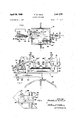
- FIGURE 1 is a plan view of the apparatus comprising a preferred embodiment of the invention
- FIGURE 2 is a side elevation of the apparatus of FIG- URE 1;
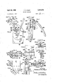
- FIGURE 3 is a side elevation of the tension head as sembly taken substantially in a direction illustrated by line 33 in FIGURE 1;
- FIGURE 4 is a plan view of the tension string clamp head associated with the tension head assembly taken in a direction indicated by line 4-4 in FIGURE 2;
- FIGURE 5 is a side elevational illustration of the clamp head of FIGURE 4.
- FIGURE 6 is an end elevational illustration of the clamp head of FIGURES 4 and 5;
- FIGURE 7 is an end elevational illustration of the string clamp mounted to the frame, and taken on line 7-7 of FIGURE 1;
- FIGURE 8 is a broken away side elevation of the sliding and clamping arrangement associated with the movable racket holding member taken from line 88 of FIGURE 1;
- FIGURE 9 is an enlarged cross sectional and elevational view of the sliding clamping mechanism of FIG- URE 8 taken from the right end thereof, but with the clamp handle shown in FIGURE 1 added thereto;
- the numeral .10 indicates generally a racket stringer particularly for tennis rackets, or the like, comprising a base 12 which in this instance is illustrated as portably mounting on a table top, or the like, but which could be a fixed or bolted base, as selectively desired.
- a substantially square and planar support frame L14 is mounted to the base 12, and preferably is in rotatable relationship thereto.
- the frame 14 mounts a substantially square rail 14b centrally thereof.
- the racket to be strung indicated in dotted lines in FIG- URE 1 is held to frame 14 by integral clamp units indicated generally by numerals 16 and 18, respectively. These units will be described more fully hereinafter.
- a tension head assembly indicated generally by numeral 20 which is slidable on a tensioning arm 22.
- the arm 22 is fixedly mounted to the post supporting frame 14 to base 12, as most clearly shown in FIGURE 2 of the drawings.
- a string clamp head indicated generally by numeral 24, is pivotally mounted to the tension head assembly 20 and actually clamps and holds the string to be tensioned by the movement of tension head assembly 24 in the proper direction along arm 22. The details of these components will be more fully described hereinafter.
- the throat of the racket is laid onto the table or support formed by clamp unit '16 with the tip of the frame just fitting over a raised lip 30 carried on the top of support bracket 38, as best seen in FIGURE 2.
- a pressure head 36 pivotally mounted to a support bracket 38 secured to an extension of frame 14 is pivoted up and tightened into position as by handle 40 to hold the tip of the racket in position.
- unit 16 which is slidable on a rail 32 carried by a mounting flange 34 is moved along rail 32 to the right as seen in FIGURE 2 until its lip 30a comes into engagement with the racket frame at the throat thereof.
- the handle 42 is tightened down to hold the throat in position.
- the structure of unit 16 is such that the tightening of handle 42 also automatically locks the unit into fixed relationship with the rail 32. A more detailed description of this structure will follow. In any event, it should be understood that the racket is now in position for stringing.
- Stringing is accomplished by engaging the string to be tightened in the string clamp head 24, and pulling it tothe desired tension by rotating a handle 44 to move the tension head 20 towards the left, as seen in FIGURE 2 until the automatic tensioning mechanism, to be more fully defined hereinafter, causes pivotal movement of clamp head 24 so as to release a catch assembly indicated generally by numeral 46, thereby locking tension head assembly 20 in fixed relationship to arm 22.
- the automatic tensioning mechanism to be more fully defined hereinafter, causes pivotal movement of clamp head 24 so as to release a catch assembly indicated generally by numeral 46, thereby locking tension head assembly 20 in fixed relationship to arm 22.
- one of the string clamps 26 is moved into position adjacent the racket frame and clamps onto the string that is tensioned.
- the long strings are normally put in first, starting from the center and stringing both ways toward the edges of the frame. Since the string is not tied to the frame at the center, some sort of a clamp is required to hold the string where it might otherwise have been tied to the frame. This sort of operation can best be accomplished with the arrangement I have, by using one clamp to hold the string at the center while working one end of it back and forth toward one edge of the frame with the other two clamps as described above.
- one long clamp bar iWhlCh reaches all the way across the long length of the rectangle formed by the rail 14b and having bearings which ride in the grooves of the opposite rails of the rectangle.
- one clamp on a short bar can be used to hold the string in the center while the other can be placed on the long bar, which can take tension and moment in either direction, and can be slid alternately from one side to the other to hold the string which is being tightened alternately in one direction then in the other toward one edge of the frame.
- the clamps can be interchanged without loosing any of the tension if the tension head is properly utilized. Then the long bar can be used to carry its clamp back and forth so as to hold the strings which are being tensioned from the center toward the other edge of the frame. Stringing is started from the center and worked both ways in order to avoid pulling the racket frame out of shape.
- Tension head assembly 20 The details of the tension head assembly 20 are best shown with relation to FIGURES 2 and 3 of the drawings, and essentially it comprises a carrying plate 50' which is slidably mounted with respect to arm 22 by guide blocks 52 and 54 removably mounted to plate 50 by appropriate bolts, and which extend slightly around the edge portion of arm 22, as best indicated in FIGURE 2 of the drawings. Also, to make the sliding movement of plate 50 on arm 22 easier, a permanent guide 56 mounted to plate 50 is provided. The actual movement of plate 50 with respect to arm 22 is achieved by a rack 58 appropriately mounted in fixed relationship to the arm 22 and a gear 60 rotatively driven by the fixed connection of handle 44 thereto.
- the handle 44 connects directly to a large circular disc 62 by appropriate bolts 64 with the disc 62 actually connected in direct locked relationship through an appropriate shaft rotatably passing through plate 50 and connected to gear 60.
- the disc 62 is held in adjacent rotatable relationship with respect to plate 50 by a pair of brackets 66 and 68 mounted to plate '50 by appropriate bolts, as best seen in FIGURE 3 of the drawings.
- the tensioning string clamp head 24 is mounted on a pivot pin 70 to a fixed bracket 71 carried by plate 50 and extending at an upwardly and outwardly directed angle thereto so as to position head 24 above and laterally toward the racket to be strung.
- the head 24 is limited, however, in its pivotal movement by an actuating bracket arm 72 affixed thereto and extending with appropriate curved configuration, as best seen in FIGURE 2 of the drawings, until a flat short end portion 74 is substantially parallel and closely spaced to the edge of one vertical side of plate 50.
- This end portion 74 engages against a stop 76 mounted to plate 50 to limit the pivotal movement of head 24 in a counter-clockwise direction so that head 24 in this limited relationship which is the normal untensioned position is normally tipped slightly back as seen in FIGURE 3, and under tension tips forward to a substantially square position whenever 104 is released.
- Pivotal movement of head 24 in the opposite or clockwise direction to drive end portion 74 to the left, as seen in FIGURE 2, is controlled by the amount of spring pressure or permanent bias applied by a helical coiled compression spring 78 carried by a plunger 80.
- the plunger 80 is rotatably received in non-sliding relationship in a bracket mounted to plate 50.
- a spring pressure regulating stop 82 is threadably received on shaft 80 whereby rotation of shaft 80 by handle 84 causes stop 82 to move to the left or right to thereby control the compression of spring 78, and hence the degree of force necessary to cause pivotal action of clamp head 24 to the right or clockwise to force end portion 74 of bracket arm 72 to compress the spring 78.
- a scale indicated generally by numeral 86, is printed on or mounted to plate 50 in relation to stop 82 so that the position of stop 82 with respect to the scale will indicate the amount of string tension that will cause pivotal action of clamp head 24 necessary to cause actuation of catch 46.
- catch 46 The actuation of catch 46 is most clearly shown with reference to FIGURE 11.
- the catch 46 usually comprises a plate 90 fixedly mounted to bracket 72 by a suitable bolt 92 from the opposite side thereof.
- a catch plate 94 is pivotally mounted to plate 90 by a pin 96 with its degree of pivotal movement being quite small and limited by its base engaging against a flush internal edge 98 of plate 90-.
- a spring 100 is provided to normally bias catch plate 94 in a clockwise or downward direction as seen in FIGURE 11.
- Catch plate 94 has a lip 94a which is adapted to hook over the end of a fiat bar 102 which is riveted to a lever 104.
- Lever 104 is biased upon such release to rotate in a clockwise direction by a suitable spring 106, as best seen in FIGURE 3.
- lever 104 rotates a nut 116 threadably received on a shaft 108 which is mounted in fixed relation by plate 50 so as to press a brake wedge 110, all as seen in FIG- URE 3, into a pressured relationship against disc 62 thereby in effect locking disc 62 into fixed relationship to plate 50.
- the threaded relationship of nut 116 with respect to shaft 108 is such that a very small arcuate rotation of lever 104 achieves the desired locking action of disc 62.
- the wedge 110 is somewhat slidably and somewhat pivotally mounted at its upper end by a pin 112 to plate 50 so that it will remain in a substantially parallel slightly pivotal position with respect thereto.
- a Washer 114 facilitates the rotative movement of lever 104 with respect to wedge 110, and transfers the clamping force caused by the inward movement of the threaded relationship of nut 116 to shaft 108 into wedge 112.
- the clamp head 24 is best seen in FIGURES 4, 5, and 6 and comprises two outer plates 120 and 122 firmly bolted together in spaced relationship and pivotally mounted to the arm extending from plate 50 by the pin 70 passing through appropriate bearings 124 in each plate.
- the actuating bracket arm 72 is appropriately bolted to plate 120 as best seen in FIGURE 6.
- Two inner plates 126 and 128 are slidable relative to the fixed outer plates 120 and 122 as they glide on four rows of rolling balls, each indicated generally by numeral 130.
- the balls 130 move in slanting receiving slots appropriately machined into the surfaces of the plates, and indicated generally by the dotted lines 132 in FIGURE 4.
- the balls are held in the slots 132 by appropriate stops 133 secured by screws 135 to the ends of outer plates 120 and 122, respectively.
- the slanting slots 132 are parallel to each other, but are slanted with respect to the plates, and hence are cut partly in the outer plates 120 and 122 and partially in the inner plates 126 and 128.
- the plates 126 and 128 are biased apart towards plates 120 and 122, respectively, by an appropriate spring 134 therebetween. It is thus seen that a movement of inner plates 126 and 128 in a direction indicated by an arrow 136 in FIGURE 4 will press the plates 126 and 128 together in a parallel motion by the action of the balls 130 rolling in slots 132.
- a bracket 140 is mounted in fixed relationship to inner plate 126 by appropriate screws and carries a spring loaded adjustable screw 142 threadably received in the downward extension thereof.
- the end of the screw 142 is adapted to abut against the spacing block holding the outer plates 120 and 122 in fixed relationship to each other, thus limiting the sliding movement of inner plates 126 and 128 relative thereto, thereby automatically limiting the closing or clamping action of inner plates 126 and 128. This adjustability prevents the clamp plates 126 and 128 from closing too far and injuring delicate strings.
- String clamps One of the string clamps 26 and 28 is shown in detail in FIGURE 7. Specifically, such clamp comprises two clamp bars and 152 which have slotted string clamping jaws 150a and 152a, respectively.
- a pair of steel plates 154 are attached to each side of the base of the bar 150, and slidably engage a bar 156 mounted in slidable relationship to the frame 14. These plates 154 are provided in spaced relationship to each other, as best seen in FIGURE 10, so that when tension is applied at the top of the clamp by engaging the string tensioned by the tensioning assembly 20, the plate 150 tilts or rotates slightly thereby clamping plates 154 with a binding action onto bar 156 to prevent the entire clamp from. sliding.
- the remaining structure of the clamp includes an actuating lever 158 pivotally secured to connecting links 160 by suitable pin 162.
- the links 160 pass through a slot 163 in bar 152 and are pivotally mounted by pin 164 to clamp bar 150.
- the end of handle 158 has a mating engaging surface at which is complementary to surface 168 of key 166.
- a downward movement of handle 158 in a direction of arrow 172 will cause the handle and links 160 to move to the chain dotted line position thereby engaging the camming surface 170 of handle 158 against the camming surface 168 of key 166 to force the jaws 150a and 152a together against the normally opposed bias of a compression spring 174.
- the camming surfaces 168 and 170 are also designed such that when the handle is down an imaginary line connecting pin 162 and pin 164 moves down below the camming surfaces 168 and 170 whereby the handle will remain down in a locked position, all as shown in the chain dotted line position of FIGURE 7. Therefore, it requires a manual effort to move the handle 158 back up to release the jaws from their locked position.
- the invention utilizes a screw 176 threadably received in clamp bar 152 which engages against the lower end of key 166 to control its spaced relationship with re spect to the outer surface of clamp bar 152.
- screw 176 As screw 176 is turned inwardly, it forces the bottom edge of key 166 away from clamp bar 152 thereby causing the camming action to move jaws 150a and 152a closer together when handle 158 is moved downwardly to the locked chain dotted line position.
- the jaws are set for their maximum width, and only an adjustment of screw 176 will move them closer together upon the movement of handle 158.
- the bar 156 has two roller bearings 180 mounted to one end which run in a groove 182 formed in the outside edge of the rail 14]) of frame 14. Another roller 184 is mounted to bar 156 to run on the inside surface of the rail 14b while still another roller 186 is mounted to the other end of bar 156 and rolls on a flat central cross frame 14a connecting between the substantially square outer rail 14b of frame 14. The upper inner lip of rail 14b is cut away, as seen in FIGURE 10 so that the entire bar 156 can be rotated in a counterclockwise direction as viewed in FIGURE 10 to remove the bar from the rail 1412.
- FIG. 8 and 9 The sliding frame clamp 16 is illustrated in greater detail in FIGURES 8 and 9 of the drawings.
- the knob 42 operates through a shaft 200 threadably received in the upper end of an L-shaped flange 202.
- a substantially rectangularly shaped clamping loop 204 is slidably received on shaft 200.
- Loop 204 is forced down by the bottom end of shaft 200 resting in a conical notch in the inside edge of the bottom by the loop. It is biased relative to flange 202 by a suitable coiled spring 206.
- the flange 202 has clamping tabs 208 and 210 firmly bolted thereto which have beveled surfaces adapted to mate with the opposed beveled surfaces of slide bar 32, as best seen in FIGURES 8 and 9.
- a lower jaw 212 has tabs 216 and 218 firmly bolted or afl'ixed thereto which also is firmly attached to flange 214 which ride on the opposed beveled surfaces of slide bar 32.
- loop 204 is crewed down by handle 42 onto the throat of the racket frame indicated by dotted lines in FIGURE 9, flange 202 is pulled upwardly while flange 214 is pushed downwardly each of which actions cause respective cocking thereof to force their respective tabs 208, 210, 216, and 218 against the opposed sides of the beveled slide bar 32.
- flange 202 tends to rotate slightly in a counter-clockwise direction as seen in FIGURE 8 while flange 214 tends to rotate slightly in a clockwise direction to achieve the desired binding, locking action of the entire clamp unit 16 onto slide bar 32. Therefore, when the racket throat is tightened the clamp unit 16 is at the same time secured relative to the frame 14.
- a device for stringing tennis rackets, and the like comprising a base, an elongated tensioning arm mounted to the base, a substantially square and planar support frame mounted to the base, so as to be pivotal around the tensioning arm in a plane substantially parallel thereto, clamp means mounted to the support frame to hold a racket in fixed relation thereto, at least one string clamp carried on the frame and slidable substantially parallel to at least one edge thereof which is characterized by a tension head carried in substantially longitudinal sliding relation on the tension arm,
- a string clamp head mounted for limited pivotal movement to the tension head and adapted to clamp and hold a string to be tightened
- tension means normally biasing the string clamp head to one limit of its pivotal movement
- locking means actuated by a preselected amount of pivotal movement of the string clamp head toward its other limit to lock the tension head in fixed relation to the tensioning arm.
- tension means normally biasing the string clamp head is adjustable to thereby provide a fixed control to the amount of tension on the string to be tightened.
- a device according to claim 1 where the string clamp head clamps onto the string to be tightened with an increasing clamping pressure as the string is further tensioned, but which includes means limiting the extent of the clamp to prevent crushing the string.
- a device where there are two clamp means and at least one of the clamp means is adjustable relative to the support frame to accommodate rackets of different size, and wherein clamping of the racket therein wedges such clamp means relative to the frame, and where the other clamp means is pivotally mounted to the frame so as to tip out of the way of a racket being positioned with respect to the frame.
- a device where there are two string clamps each adjustable to be slidable substantially parallel relative to any edge of the support frame and which clamps further include means limiting the extent of clamp to prevent crushing the string, and which locks when in clamped relation, and which includes lever means with a high mechanical advantage to accomplish clamping.
- a device where the means to move the tension head along the tension arm is a rack fixed to the arm and a gear engaging the rack rotatably mounted by the tension head, means to rotate the gear, and where the locking means comprises a latch unit mounted to the string clamp head, a biased locking lever normally retained by the latch unit, but released upon a predetermined pivotal movement of the string clamp head against its biased direction to lock the gear in nonrotatable relation to the tension head.
- both string clamps are normally movable both parallel and transversely relative to any edge of the support frame, but when actuated to clamp a string under tension they are simultaneously locked relative to the frame in the direction of the tension on the string.
- a device for stringing tennis rackets and the like comprising a base, a substantially planar support frame mounted to the base, an elongated tensioning arm mounted to the base whereby the frame and arm are pivoted with respect to each other in a plane substantially parallel thereto, clamp means mounted to the support frame to hold a racket in fixed relation thereto, at least one string clamp mounted on the frame but movable relative thereto which is characterized by a tension head assembly carried in sliding relation on the tensioning arm,
- a string cla-mp head mounted for limited pivotal movement to the tension head and adapted to clamp and hold a string to be tightened whereby tensioning of the string tends to cause pivotal movement of the clamp head to one limit of its pivotal movement
- manually actuated means to slide the tension head along the tensioning arm to tension a string held by the string clamp head whereby pivot-a1 movement of the clamp head toward said one limit is actuated
- locking means mounted to the .tension head assembly released by a preselected amount of pivotal movement of the string clamp head towards its one limit to lock the tension held in relation to the tensioning arm.
- a device where the means biasing the string clam-p head is a helically coiled compression spring and whereby the amount of bias is controllable by adjustability of the compression of said spring.
- the string clamp head comprises a pair of connected parallel spaced outer plates pivotally mounted to the tension head assembly, a pair of inner plates each normally biased towards its respective outer plate, where each inner and outer plate combination has at least one groove commonly aligned thereto which in effect is angled in relation to the parallel surfaces of the plates, ball means slidably received in the grooves whereby relative movement between the inner and outer plates is limited to a linear motion and the inner plates move in parallel relation toward each other upon a movement of the inner plates linearly in a predetermined direction, and adjustable stop means secured to one of the inner plates to engage any fixed portion of the clamp head to limit the linear movement of said inner plates in said predetermined direction.
Landscapes
- Health & Medical Sciences (AREA)
- General Health & Medical Sciences (AREA)
- Physical Education & Sports Medicine (AREA)
- Basic Packing Technique (AREA)
Description
April 29, 1969 F w. HELD RACKET STRINGER- Sheet of 2 FiledM aroh s, 1967 ATTORN E YsL April 29, 1969 F, w, HELD 3,441, 75
RACKET S'I RINGER Filed March 5. 1967 r Sheet orz Bo izo F'|G.5 INVENTOR.
FRANKLIN W. HELD ATTORNEYS! United States Patent 3,441,275 RACKET STRINGER Franklin W. Held, 928 Orma Drive, San Diego, Calif. 92106 Filed Mar. 3, 1967, Ser. No. 620,536 Int. Cl. A63b 51/14 US. 'Cl. 27373 Claims ABSTRACT OF THE DISCLOSURE Prior art Heretofore it has been known that there have been many and various types of machines and apparatus for stringing rackets such as those shown, for example, in US. Patents Nos. 2,389,609, 2,971,760 and 2,100,948. However, none of these patents utilize a tensioning mechanism which automatically provides the desired tension by a simple manual rotation of a crank and when the desired tension is reached without any knowledge or skill of the operator, the tensioning mechanism is locked into position to permit engagement of the clamps with the strings to hold the string under tension and in position. None of these prior art mechanisms utilize such a tensioning device to take all of the guess work and human error out of the operation of the equipment. Further, the prior art has not recognized fully the problem inherent in clamping the strings. Namely, that the clamping of the strings must be sufiicient to firmly hold the strings, but not so hard as to crush and damage them. The above identified prior art and other patents such as Patent Nos. 2,131,880 and 2,262,110 do not control the amount of clamping pressure onto the strings in a positive manner so as to eliminate crushing.
It is the general object of the present invention to overcome the inherent ditficulties of and objections to the prior art in racket stringing apparatus by providing an apparatus which automatically achieves the proper tension and holds it while the strings are clamped and held in position, and wherein all clamps utilized for holding the string are actuated only sufiiciently to firmly hold, but not crush the strings in the racket.
A further object of the invention is to provide a racket stringer which is adjustable for rackets of different size, and wherein the stringing can be quickly and positively accomplished by the ability to change the tensioning head with respect to the racket being held, and at the same time change the string clamping mechanism.
A further object of the invention is to provide a simple, highly reliable, yet inexpensive racket stringer which may be portable, and which is adjustable to be utilized for rackets of various size and strings of various size associated with the rackets.
The aforesaid objects of the invention and other objects which will become apparent as the description proceeds are achieved by providing in a device for stringing tennis rackets and the like, a base, a substantially square and planar support frame mounted to the base, an elon- 3,441,275 Patented Apr. 29, 1969 gated tensioning arm mounted to the base so as to be pivotal around the support frame in a plane substantially parallel thereto, clamp means mounted to the support frame to hold a racket in fixed relation thereto, at least one string clamp carried on the frame and slidable substantially parallel to at least one edge thereof which is characterized by a tension head carried in substantially longitudinal sliding relation on the tension arm, a string clamp head mounted for limited pivotal movement to the tension head and adapted to clamp and hold a string to be tightened, tension means normally biasing the string clamp head to one limit of its pivotal movement, means to move the tension head along the tensioning arm to tighten a string held by the string clamp head, and locking means actuated by a preselected amount of pivotal movement of the string clamp head toward its other limit to lock the tension head in fixed relation to the tensioning arm.
Description of the drawings For a better understanding of the invention reference should be had to the accompanying drawings wherein:
FIGURE 1 is a plan view of the apparatus comprising a preferred embodiment of the invention;
FIGURE 2 is a side elevation of the apparatus of FIG- URE 1;
FIGURE 3 is a side elevation of the tension head as sembly taken substantially in a direction illustrated by line 33 in FIGURE 1;
FIGURE 4 is a plan view of the tension string clamp head associated with the tension head assembly taken in a direction indicated by line 4-4 in FIGURE 2;
FIGURE 5 is a side elevational illustration of the clamp head of FIGURE 4;
FIGURE 6 is an end elevational illustration of the clamp head of FIGURES 4 and 5;
FIGURE 7 is an end elevational illustration of the string clamp mounted to the frame, and taken on line 7-7 of FIGURE 1;
FIGURE 8 is a broken away side elevation of the sliding and clamping arrangement associated with the movable racket holding member taken from line 88 of FIGURE 1;
FIGURE 9 is an enlarged cross sectional and elevational view of the sliding clamping mechanism of FIG- URE 8 taken from the right end thereof, but with the clamp handle shown in FIGURE 1 added thereto;
Description of the invention With reference to the form of the invention illustrated in FIGURES 1 and 2 of the drawings, the numeral .10 indicates generally a racket stringer particularly for tennis rackets, or the like, comprising a base 12 which in this instance is illustrated as portably mounting on a table top, or the like, but which could be a fixed or bolted base, as selectively desired. A substantially square and planar support frame L14 is mounted to the base 12, and preferably is in rotatable relationship thereto. The frame 14 mounts a substantially square rail 14b centrally thereof. The racket to be strung indicated in dotted lines in FIG- URE 1 is held to frame 14 by integral clamp units indicated generally by numerals 16 and 18, respectively. These units will be described more fully hereinafter. Normally, the tip of the racket is held in damp unit 18 While the throat is held at clamp unit 16. Actual tensioning is provided by a tension head assembly indicated generally by numeral 20 which is slidable on a tensioning arm 22. The arm 22 is fixedly mounted to the post supporting frame 14 to base 12, as most clearly shown in FIGURE 2 of the drawings. A string clamp head, indicated generally by numeral 24, is pivotally mounted to the tension head assembly 20 and actually clamps and holds the string to be tensioned by the movement of tension head assembly 24 in the proper direction along arm 22. The details of these components will be more fully described hereinafter. Once the string has been tensioned, it can be then fully retained in its tensioned position by the appropriate one of separate string clamps, each indicated generally by numerals 26 and 28, respectively.
In order to position a racket in the assembly, the throat of the racket is laid onto the table or support formed by clamp unit '16 with the tip of the frame just fitting over a raised lip 30 carried on the top of support bracket 38, as best seen in FIGURE 2. Once the tip of the racket is in position over raised flange 30, a pressure head 36 pivotally mounted to a support bracket 38 secured to an extension of frame 14 is pivoted up and tightened into position as by handle 40 to hold the tip of the racket in position. At this time, unit 16 which is slidable on a rail 32 carried by a mounting flange 34 is moved along rail 32 to the right as seen in FIGURE 2 until its lip 30a comes into engagement with the racket frame at the throat thereof. At this time, the handle 42 is tightened down to hold the throat in position. The structure of unit 16 is such that the tightening of handle 42 also automatically locks the unit into fixed relationship with the rail 32. A more detailed description of this structure will follow. In any event, it should be understood that the racket is now in position for stringing.
Stringing is accomplished by engaging the string to be tightened in the string clamp head 24, and pulling it tothe desired tension by rotating a handle 44 to move the tension head 20 towards the left, as seen in FIGURE 2 until the automatic tensioning mechanism, to be more fully defined hereinafter, causes pivotal movement of clamp head 24 so as to release a catch assembly indicated generally by numeral 46, thereby locking tension head assembly 20 in fixed relationship to arm 22. At this point one of the string clamps 26 is moved into position adjacent the racket frame and clamps onto the string that is tensioned. The clamping action of either unit 26 or 28 automatically locks it with respect to frame 14 and maintains the tension on the string to allow release by clamp head 24, a pivot of the entire frame 14 around to allow assembly 20 to grasp and pull the string in the opposite direction for the next tensioning operation. Naturally, upon the next tensioning, the string clamp will be utilized on the opposite side of the racket frame in the same manner described above. This procedure is followed until all the strings in one direction of the frame have been strung, and then the string clamps 26 and 28 are moved to the other parallel sides of frame 14, from that shown in FIG- URE 1, as will be more fully defined hereinafter, so that the strings in perpendicular or transverse relationship can be strung and tensioned. Thus, it can be seen that the operation of the device is very quick, highly reliable, and very simple.
In some instances it is desirable to use three string clamps. The long strings are normally put in first, starting from the center and stringing both ways toward the edges of the frame. Since the string is not tied to the frame at the center, some sort of a clamp is required to hold the string where it might otherwise have been tied to the frame. This sort of operation can best be accomplished with the arrangement I have, by using one clamp to hold the string at the center while working one end of it back and forth toward one edge of the frame with the other two clamps as described above.
It is possible to accomplish this sort of stringing with two clamps by providing in addition to the two clamps and two short clamp bars, one long clamp bar iWhlCh. reaches all the way across the long length of the rectangle formed by the rail 14b and having bearings which ride in the grooves of the opposite rails of the rectangle. This way one clamp on a short bar can be used to hold the string in the center while the other can be placed on the long bar, which can take tension and moment in either direction, and can be slid alternately from one side to the other to hold the string which is being tightened alternately in one direction then in the other toward one edge of the frame. As soon as three or four strings are in place from the center toward one edge of the frame, then the clamps can be interchanged without loosing any of the tension if the tension head is properly utilized. Then the long bar can be used to carry its clamp back and forth so as to hold the strings which are being tensioned from the center toward the other edge of the frame. Stringing is started from the center and worked both ways in order to avoid pulling the racket frame out of shape.
The specific construction of the component features of the invention will be more fully described hereinbelow, now that it is understood exactly how each component functions in the overall combination.
Tension head assembly The details of the tension head assembly 20 are best shown with relation to FIGURES 2 and 3 of the drawings, and essentially it comprises a carrying plate 50' which is slidably mounted with respect to arm 22 by guide blocks 52 and 54 removably mounted to plate 50 by appropriate bolts, and which extend slightly around the edge portion of arm 22, as best indicated in FIGURE 2 of the drawings. Also, to make the sliding movement of plate 50 on arm 22 easier, a permanent guide 56 mounted to plate 50 is provided. The actual movement of plate 50 with respect to arm 22 is achieved by a rack 58 appropriately mounted in fixed relationship to the arm 22 and a gear 60 rotatively driven by the fixed connection of handle 44 thereto. Essentially, as best seen in FIGURE 3, the handle 44 connects directly to a large circular disc 62 by appropriate bolts 64 with the disc 62 actually connected in direct locked relationship through an appropriate shaft rotatably passing through plate 50 and connected to gear 60. The disc 62 is held in adjacent rotatable relationship with respect to plate 50 by a pair of brackets 66 and 68 mounted to plate '50 by appropriate bolts, as best seen in FIGURE 3 of the drawings.
The tensioning string clamp head 24 is mounted on a pivot pin 70 to a fixed bracket 71 carried by plate 50 and extending at an upwardly and outwardly directed angle thereto so as to position head 24 above and laterally toward the racket to be strung. The head 24 is limited, however, in its pivotal movement by an actuating bracket arm 72 affixed thereto and extending with appropriate curved configuration, as best seen in FIGURE 2 of the drawings, until a flat short end portion 74 is substantially parallel and closely spaced to the edge of one vertical side of plate 50. This end portion 74 engages against a stop 76 mounted to plate 50 to limit the pivotal movement of head 24 in a counter-clockwise direction so that head 24 in this limited relationship which is the normal untensioned position is normally tipped slightly back as seen in FIGURE 3, and under tension tips forward to a substantially square position whenever 104 is released.
Pivotal movement of head 24 in the opposite or clockwise direction to drive end portion 74 to the left, as seen in FIGURE 2, is controlled by the amount of spring pressure or permanent bias applied by a helical coiled compression spring 78 carried by a plunger 80. The plunger 80 is rotatably received in non-sliding relationship in a bracket mounted to plate 50. A spring pressure regulating stop 82 is threadably received on shaft 80 whereby rotation of shaft 80 by handle 84 causes stop 82 to move to the left or right to thereby control the compression of spring 78, and hence the degree of force necessary to cause pivotal action of clamp head 24 to the right or clockwise to force end portion 74 of bracket arm 72 to compress the spring 78. A scale, indicated generally by numeral 86, is printed on or mounted to plate 50 in relation to stop 82 so that the position of stop 82 with respect to the scale will indicate the amount of string tension that will cause pivotal action of clamp head 24 necessary to cause actuation of catch 46.
The actuation of catch 46 is most clearly shown with reference to FIGURE 11. When the desired string tension is reached the entire catch assembly 46 being fixedly mounted to the bracket arm 72 rotates upwardly, or in a direction indicated by an arrow 88 in FIGURE 11. The catch 46 usually comprises a plate 90 fixedly mounted to bracket 72 by a suitable bolt 92 from the opposite side thereof. A catch plate 94 is pivotally mounted to plate 90 by a pin 96 with its degree of pivotal movement being quite small and limited by its base engaging against a flush internal edge 98 of plate 90-. A spring 100 is provided to normally bias catch plate 94 in a clockwise or downward direction as seen in FIGURE 11. Catch plate 94 has a lip 94a which is adapted to hook over the end of a fiat bar 102 which is riveted to a lever 104. Thus, it is seen that when clamp head 24 rotates in a direction indicated by arrow 88 in FIGURE 11, the lip 94a of catch plate 94 slips over the end of bar 102 thereby releasing lever 104. Lever 104 is biased upon such release to rotate in a clockwise direction by a suitable spring 106, as best seen in FIGURE 3. The clockwise rotation of lever 104 rotates a nut 116 threadably received on a shaft 108 which is mounted in fixed relation by plate 50 so as to press a brake wedge 110, all as seen in FIG- URE 3, into a pressured relationship against disc 62 thereby in effect locking disc 62 into fixed relationship to plate 50. The threaded relationship of nut 116 with respect to shaft 108 is such that a very small arcuate rotation of lever 104 achieves the desired locking action of disc 62. The wedge 110 is somewhat slidably and somewhat pivotally mounted at its upper end by a pin 112 to plate 50 so that it will remain in a substantially parallel slightly pivotal position with respect thereto. A Washer 114 facilitates the rotative movement of lever 104 with respect to wedge 110, and transfers the clamping force caused by the inward movement of the threaded relationship of nut 116 to shaft 108 into wedge 112.
Thus, it is seen that rotation or pivotal action of string clamp head 24 occurs only when the proper tension on the string is achieved as determined by the adjusted position on compression spring 78, and that when this proper tension is received lever 104 is released to clamp disc 62 in fixed position to plate 50 and thus lock arm 44 so that no further movement of assembly 20 can occur. After the tensioned string is held in position with one of the appropriate string clamps 26 or 28, lever 104 can be manually rotated in a counter-clockwise direction against the tension of spring 106 to the catch position. In this situation, as seen in FIGURE 11, the bar 102 hits the lip 94a which causes the rotation of plate 94 around pin 96 against compression spring 100. When lever 104 is pushed far enough to the left or in counterclockwise direction the lip 94a springs down over the end of bar 102 by action of spring 100 so as to hold lever 104 in the upright position indicated in the drawings.
String clam-p head The clamp head 24 is best seen in FIGURES 4, 5, and 6 and comprises two outer plates 120 and 122 firmly bolted together in spaced relationship and pivotally mounted to the arm extending from plate 50 by the pin 70 passing through appropriate bearings 124 in each plate. The actuating bracket arm 72 is appropriately bolted to plate 120 as best seen in FIGURE 6. Two inner plates 126 and 128 are slidable relative to the fixed outer plates 120 and 122 as they glide on four rows of rolling balls, each indicated generally by numeral 130. The balls 130 move in slanting receiving slots appropriately machined into the surfaces of the plates, and indicated generally by the dotted lines 132 in FIGURE 4. The balls are held in the slots 132 by appropriate stops 133 secured by screws 135 to the ends of outer plates 120 and 122, respectively. It should be noted that the slanting slots 132 are parallel to each other, but are slanted with respect to the plates, and hence are cut partly in the outer plates 120 and 122 and partially in the inner plates 126 and 128. The plates 126 and 128 are biased apart towards plates 120 and 122, respectively, by an appropriate spring 134 therebetween. It is thus seen that a movement of inner plates 126 and 128 in a direction indicated by an arrow 136 in FIGURE 4 will press the plates 126 and 128 together in a parallel motion by the action of the balls 130 rolling in slots 132.
In order to limit the parallel movement of plates 126 and 128 together, a bracket 140 is mounted in fixed relationship to inner plate 126 by appropriate screws and carries a spring loaded adjustable screw 142 threadably received in the downward extension thereof. The end of the screw 142 is adapted to abut against the spacing block holding the outer plates 120 and 122 in fixed relationship to each other, thus limiting the sliding movement of inner plates 126 and 128 relative thereto, thereby automatically limiting the closing or clamping action of inner plates 126 and 128. This adjustability prevents the clamp plates 126 and 128 from closing too far and injuring delicate strings. From the foregoing, it should be understood that when a string to be tensioned is laid between the plates 126 and 128, they can be moved manually forward to automatically clamp the string, and the actual pulling of the string in the direction of arrow 136 in FIGURE 4 only serves to further clamp and firmly hold the string in position during the tensioning arrangement with the assembly 20 described above.
String clamps One of the string clamps 26 and 28 is shown in detail in FIGURE 7. Specifically, such clamp comprises two clamp bars and 152 which have slotted string clamping jaws 150a and 152a, respectively. A pair of steel plates 154, preferably hardened, are attached to each side of the base of the bar 150, and slidably engage a bar 156 mounted in slidable relationship to the frame 14. These plates 154 are provided in spaced relationship to each other, as best seen in FIGURE 10, so that when tension is applied at the top of the clamp by engaging the string tensioned by the tensioning assembly 20, the plate 150 tilts or rotates slightly thereby clamping plates 154 with a binding action onto bar 156 to prevent the entire clamp from. sliding.
The remaining structure of the clamp includes an actuating lever 158 pivotally secured to connecting links 160 by suitable pin 162. The links 160 pass through a slot 163 in bar 152 and are pivotally mounted by pin 164 to clamp bar 150. A key 166 having a contoured cam like surface, indicated by the dotted line 168, fits into the slot 163 in clamp bar 152 between the links 160, as seen in FIGURE 7. The end of handle 158 has a mating engaging surface at which is complementary to surface 168 of key 166. A downward movement of handle 158 in a direction of arrow 172 will cause the handle and links 160 to move to the chain dotted line position thereby engaging the camming surface 170 of handle 158 against the camming surface 168 of key 166 to force the jaws 150a and 152a together against the normally opposed bias of a compression spring 174. The camming surfaces 168 and 170 are also designed such that when the handle is down an imaginary line connecting pin 162 and pin 164 moves down below the camming surfaces 168 and 170 whereby the handle will remain down in a locked position, all as shown in the chain dotted line position of FIGURE 7. Therefore, it requires a manual effort to move the handle 158 back up to release the jaws from their locked position.
In order to provide an adjustability to the degree of clamping by jaws 150a and 152a so as not to injure delicate string, the invention utilizes a screw 176 threadably received in clamp bar 152 which engages against the lower end of key 166 to control its spaced relationship with re spect to the outer surface of clamp bar 152. In other words, as screw 176 is turned inwardly, it forces the bottom edge of key 166 away from clamp bar 152 thereby causing the camming action to move jaws 150a and 152a closer together when handle 158 is moved downwardly to the locked chain dotted line position. In FIGURE 7, the jaws are set for their maximum width, and only an adjustment of screw 176 will move them closer together upon the movement of handle 158.
String clamp bar The details of bar 156 and its mounting relationship to frame 14 are best shown with respect to FIGURE 10 of the drawings. Specifically, the bar 156 has two roller bearings 180 mounted to one end which run in a groove 182 formed in the outside edge of the rail 14]) of frame 14. Another roller 184 is mounted to bar 156 to run on the inside surface of the rail 14b while still another roller 186 is mounted to the other end of bar 156 and rolls on a flat central cross frame 14a connecting between the substantially square outer rail 14b of frame 14. The upper inner lip of rail 14b is cut away, as seen in FIGURE 10 so that the entire bar 156 can be rotated in a counterclockwise direction as viewed in FIGURE 10 to remove the bar from the rail 1412. This is necessary when switching the clamps from lengthwise to crosswise stringing as explained earlier. Also, it should be noted at this point that the plates 154 connected to clamp bar 150 are notched at 154a to allow removal of the clamps from bar 156. This is accomplished by rotating the entire string clamp 90 from that position shown in FIGURE 10 on bar 156 so that the notches 154a will slide over the small bracket connecting rollers 186 and 156.
Frame clamp The sliding frame clamp 16 is illustrated in greater detail in FIGURES 8 and 9 of the drawings. The knob 42 operates through a shaft 200 threadably received in the upper end of an L-shaped flange 202. A substantially rectangularly shaped clamping loop 204 is slidably received on shaft 200. Loop 204 is forced down by the bottom end of shaft 200 resting in a conical notch in the inside edge of the bottom by the loop. It is biased relative to flange 202 by a suitable coiled spring 206. The flange 202 has clamping tabs 208 and 210 firmly bolted thereto which have beveled surfaces adapted to mate with the opposed beveled surfaces of slide bar 32, as best seen in FIGURES 8 and 9. A lower jaw 212 has tabs 216 and 218 firmly bolted or afl'ixed thereto which also is firmly attached to flange 214 which ride on the opposed beveled surfaces of slide bar 32. Thus, it should be understood that as loop 204 is crewed down by handle 42 onto the throat of the racket frame indicated by dotted lines in FIGURE 9, flange 202 is pulled upwardly while flange 214 is pushed downwardly each of which actions cause respective cocking thereof to force their respective tabs 208, 210, 216, and 218 against the opposed sides of the beveled slide bar 32. In other words, flange 202 tends to rotate slightly in a counter-clockwise direction as seen in FIGURE 8 while flange 214 tends to rotate slightly in a clockwise direction to achieve the desired binding, locking action of the entire clamp unit 16 onto slide bar 32. Therefore, when the racket throat is tightened the clamp unit 16 is at the same time secured relative to the frame 14.
While in accordance with the patent statutes only one best known embodiment of the invention has been illustrated and described in detail, it is to be particularly understood that the invention is not limited thereto or thereby, but the inventive scope is defined in the appended claims.
What is claimed is:
1. A device for stringing tennis rackets, and the like, comprising a base, an elongated tensioning arm mounted to the base, a substantially square and planar support frame mounted to the base, so as to be pivotal around the tensioning arm in a plane substantially parallel thereto, clamp means mounted to the support frame to hold a racket in fixed relation thereto, at least one string clamp carried on the frame and slidable substantially parallel to at least one edge thereof which is characterized by a tension head carried in substantially longitudinal sliding relation on the tension arm,
a string clamp head mounted for limited pivotal movement to the tension head and adapted to clamp and hold a string to be tightened,
tension means normally biasing the string clamp head to one limit of its pivotal movement,
means to move the tension head along the tensioning arm to tighten a string held by the string clamp head, and
locking means actuated by a preselected amount of pivotal movement of the string clamp head toward its other limit to lock the tension head in fixed relation to the tensioning arm.
2. A device according to claim 1 where the tension means normally biasing the string clamp head is adjustable to thereby provide a fixed control to the amount of tension on the string to be tightened.
3. A device according to claim 1 where the string clamp head clamps onto the string to be tightened with an increasing clamping pressure as the string is further tensioned, but which includes means limiting the extent of the clamp to prevent crushing the string.
4. A device according to claim 1 where there are two clamp means and at least one of the clamp means is adjustable relative to the support frame to accommodate rackets of different size, and wherein clamping of the racket therein wedges such clamp means relative to the frame, and where the other clamp means is pivotally mounted to the frame so as to tip out of the way of a racket being positioned with respect to the frame.
5. A device according to claim 1 where there are two string clamps each adjustable to be slidable substantially parallel relative to any edge of the support frame and which clamps further include means limiting the extent of clamp to prevent crushing the string, and which locks when in clamped relation, and which includes lever means with a high mechanical advantage to accomplish clamping.
6. A device according to claim -1 where the means to move the tension head along the tension arm is a rack fixed to the arm and a gear engaging the rack rotatably mounted by the tension head, means to rotate the gear, and where the locking means comprises a latch unit mounted to the string clamp head, a biased locking lever normally retained by the latch unit, but released upon a predetermined pivotal movement of the string clamp head against its biased direction to lock the gear in nonrotatable relation to the tension head.
7. A device according to claim 5 where both string clamps are normally movable both parallel and transversely relative to any edge of the support frame, but when actuated to clamp a string under tension they are simultaneously locked relative to the frame in the direction of the tension on the string.
8. A device for stringing tennis rackets and the like comprising a base, a substantially planar support frame mounted to the base, an elongated tensioning arm mounted to the base whereby the frame and arm are pivoted with respect to each other in a plane substantially parallel thereto, clamp means mounted to the support frame to hold a racket in fixed relation thereto, at least one string clamp mounted on the frame but movable relative thereto which is characterized by a tension head assembly carried in sliding relation on the tensioning arm,
a string cla-mp head mounted for limited pivotal movement to the tension head and adapted to clamp and hold a string to be tightened whereby tensioning of the string tends to cause pivotal movement of the clamp head to one limit of its pivotal movement,
means normally biasing the string clamp head to the other limit of its pivotal movement to oppose the tendency of the tensioning of the string to pivot the clamp head,
manually actuated means to slide the tension head along the tensioning arm to tension a string held by the string clamp head whereby pivot-a1 movement of the clamp head toward said one limit is actuated, and
locking means mounted to the .tension head assembly released by a preselected amount of pivotal movement of the string clamp head towards its one limit to lock the tension held in relation to the tensioning arm.
9. A device according to claim 8 where the means biasing the string clam-p head is a helically coiled compression spring and whereby the amount of bias is controllable by adjustability of the compression of said spring.
10. A device according to claim 8 where the string clamp head comprises a pair of connected parallel spaced outer plates pivotally mounted to the tension head assembly, a pair of inner plates each normally biased towards its respective outer plate, where each inner and outer plate combination has at least one groove commonly aligned thereto which in effect is angled in relation to the parallel surfaces of the plates, ball means slidably received in the grooves whereby relative movement between the inner and outer plates is limited to a linear motion and the inner plates move in parallel relation toward each other upon a movement of the inner plates linearly in a predetermined direction, and adjustable stop means secured to one of the inner plates to engage any fixed portion of the clamp head to limit the linear movement of said inner plates in said predetermined direction.
References Cited UNITED STATES PATENTS 2,06 9,-736 2/ 1937 Roberts. 2,100,948 11/1937 Doll. 2,154,870 4/ 1939 Serrano. 2,188,250 1/ 1940 Serrano.
RICHARD C. PINKHAM, Primary Examiner. THEATRICE BROWN, Assistant Examiner.
U.S. Cl. X.R. 73 145
Applications Claiming Priority (1)
| Application Number | Priority Date | Filing Date | Title |
|---|---|---|---|
| US62053667A | 1967-03-03 | 1967-03-03 |
Publications (1)
| Publication Number | Publication Date |
|---|---|
| US3441275A true US3441275A (en) | 1969-04-29 |
Family
ID=24486352
Family Applications (1)
| Application Number | Title | Priority Date | Filing Date |
|---|---|---|---|
| US620536A Expired - Lifetime US3441275A (en) | 1967-03-03 | 1967-03-03 | Racket stringer |
Country Status (1)
| Country | Link |
|---|---|
| US (1) | US3441275A (en) |
Cited By (23)
| Publication number | Priority date | Publication date | Assignee | Title |
|---|---|---|---|---|
| US3635080A (en) * | 1968-05-31 | 1972-01-18 | Court & Slope Inc | Racket-stringing machine with automatic locking |
| US3823609A (en) * | 1973-01-15 | 1974-07-16 | Tremont Res Co Inc | String tensioning mechanism |
| US3918713A (en) * | 1974-03-15 | 1975-11-11 | Bernard Kaminstein | Racket stringing machine |
| US3988022A (en) * | 1975-06-04 | 1976-10-26 | Tennis Machines, Inc. | Racket stringing machine |
| US4125259A (en) * | 1977-06-23 | 1978-11-14 | Tennis Machines, Inc. | String clamping device and support structure therefor for racket and like stringing machines |
| US4156525A (en) * | 1977-10-03 | 1979-05-29 | Parnell Paul E | Racket stringing apparatus |
| WO1980001649A1 (en) * | 1979-02-12 | 1980-08-21 | J Balaban | String pre-stretching apparatus and method for racket-stringing machine |
| FR2460688A1 (en) * | 1979-07-10 | 1981-01-30 | Montana Sport | Jig for stringing racquet - has frame clamped in cradle and string held in tension by slide moving along guides |
| EP0026008A1 (en) * | 1979-09-04 | 1981-04-01 | FISCHER INDUSTRIES personenvennootschap met beperkte aansprakelijkheid | Device for stringing rackets |
| EP0034688A3 (en) * | 1980-02-18 | 1981-11-11 | Snauwaert & Depla Societe Belge | Machine for stringing rackets |
| US4326713A (en) * | 1979-02-12 | 1982-04-27 | Balaban J A | Racket stringing apparatus and method |
| US4348024A (en) * | 1979-02-12 | 1982-09-07 | Balaban J A | Racket stringing apparatus and method |
| US4366958A (en) * | 1980-06-23 | 1983-01-04 | Tennis Machines, Inc. | Racket stringing machines |
| US4417729A (en) * | 1982-02-26 | 1983-11-29 | Prince Manufacturing, Inc. | Racket stringing apparatus |
| US4484742A (en) * | 1982-11-22 | 1984-11-27 | Mccrone James G | Stringing tool for tennis rackets and the like |
| US4494752A (en) * | 1983-04-11 | 1985-01-22 | Ray Lynn L | Racket stringer and tensioner |
| US4706955A (en) * | 1986-05-20 | 1987-11-17 | Sumiaty Ngadi | Racket frame clamp for stringing machine |
| WO1995011728A1 (en) * | 1993-10-26 | 1995-05-04 | Prince Sports Group, Inc. | Racquet stringing machine |
| US5733212A (en) * | 1996-10-08 | 1998-03-31 | Wise U. S. A., Inc. | Electronic racket stringing machine |
| US6398674B2 (en) * | 2000-05-02 | 2002-06-04 | Akira Tsuchida | Gut-clamping mechanism in gut-stretching equipment for tennis rackets |
| CN100569320C (en) * | 2007-07-06 | 2009-12-16 | 李俊杰 | Wire drawing device height adjusting device of wire drawing machine head of racket threading machine |
| US20150258389A1 (en) * | 2014-03-17 | 2015-09-17 | Vaclav Zdrazila | Portable Tennis Racket Stringing Machine |
| FR3027810A1 (en) * | 2014-10-31 | 2016-05-06 | Babolat Vs | RACKET STRAP TENSIONING SYSTEM AND CORDERING MACHINE COMPRISING SUCH A SYSTEM |
Citations (4)
| Publication number | Priority date | Publication date | Assignee | Title |
|---|---|---|---|---|
| US2069736A (en) * | 1933-08-23 | 1937-02-02 | Thompson Mfg Co | Tennis racket vise |
| US2100948A (en) * | 1936-11-25 | 1937-11-30 | Doll Air Stringer Of America I | Apparatus for stringing rackets |
| US2154870A (en) * | 1936-06-10 | 1939-04-18 | Edmundo H Serrano | Apparatus for stringing tennis rackets |
| US2188250A (en) * | 1938-10-14 | 1940-01-23 | Edmundo H Serrano | Racket stringing apparatus |
-
1967
- 1967-03-03 US US620536A patent/US3441275A/en not_active Expired - Lifetime
Patent Citations (4)
| Publication number | Priority date | Publication date | Assignee | Title |
|---|---|---|---|---|
| US2069736A (en) * | 1933-08-23 | 1937-02-02 | Thompson Mfg Co | Tennis racket vise |
| US2154870A (en) * | 1936-06-10 | 1939-04-18 | Edmundo H Serrano | Apparatus for stringing tennis rackets |
| US2100948A (en) * | 1936-11-25 | 1937-11-30 | Doll Air Stringer Of America I | Apparatus for stringing rackets |
| US2188250A (en) * | 1938-10-14 | 1940-01-23 | Edmundo H Serrano | Racket stringing apparatus |
Cited By (26)
| Publication number | Priority date | Publication date | Assignee | Title |
|---|---|---|---|---|
| US3635080A (en) * | 1968-05-31 | 1972-01-18 | Court & Slope Inc | Racket-stringing machine with automatic locking |
| US3823609A (en) * | 1973-01-15 | 1974-07-16 | Tremont Res Co Inc | String tensioning mechanism |
| US3918713A (en) * | 1974-03-15 | 1975-11-11 | Bernard Kaminstein | Racket stringing machine |
| US3988022A (en) * | 1975-06-04 | 1976-10-26 | Tennis Machines, Inc. | Racket stringing machine |
| US4125259A (en) * | 1977-06-23 | 1978-11-14 | Tennis Machines, Inc. | String clamping device and support structure therefor for racket and like stringing machines |
| US4156525A (en) * | 1977-10-03 | 1979-05-29 | Parnell Paul E | Racket stringing apparatus |
| US4348024A (en) * | 1979-02-12 | 1982-09-07 | Balaban J A | Racket stringing apparatus and method |
| US4249732A (en) * | 1979-02-12 | 1981-02-10 | Balaban J A | String pre-stretching apparatus and method for racket stringing machine |
| US4326713A (en) * | 1979-02-12 | 1982-04-27 | Balaban J A | Racket stringing apparatus and method |
| WO1980001649A1 (en) * | 1979-02-12 | 1980-08-21 | J Balaban | String pre-stretching apparatus and method for racket-stringing machine |
| FR2460688A1 (en) * | 1979-07-10 | 1981-01-30 | Montana Sport | Jig for stringing racquet - has frame clamped in cradle and string held in tension by slide moving along guides |
| EP0026008A1 (en) * | 1979-09-04 | 1981-04-01 | FISCHER INDUSTRIES personenvennootschap met beperkte aansprakelijkheid | Device for stringing rackets |
| EP0034688A3 (en) * | 1980-02-18 | 1981-11-11 | Snauwaert & Depla Societe Belge | Machine for stringing rackets |
| US4376535A (en) * | 1980-02-18 | 1983-03-15 | Snauwaert & Depla | Machine for stringing rackets |
| US4366958A (en) * | 1980-06-23 | 1983-01-04 | Tennis Machines, Inc. | Racket stringing machines |
| US4417729A (en) * | 1982-02-26 | 1983-11-29 | Prince Manufacturing, Inc. | Racket stringing apparatus |
| US4484742A (en) * | 1982-11-22 | 1984-11-27 | Mccrone James G | Stringing tool for tennis rackets and the like |
| US4494752A (en) * | 1983-04-11 | 1985-01-22 | Ray Lynn L | Racket stringer and tensioner |
| US4706955A (en) * | 1986-05-20 | 1987-11-17 | Sumiaty Ngadi | Racket frame clamp for stringing machine |
| WO1995011728A1 (en) * | 1993-10-26 | 1995-05-04 | Prince Sports Group, Inc. | Racquet stringing machine |
| US5733212A (en) * | 1996-10-08 | 1998-03-31 | Wise U. S. A., Inc. | Electronic racket stringing machine |
| US6398674B2 (en) * | 2000-05-02 | 2002-06-04 | Akira Tsuchida | Gut-clamping mechanism in gut-stretching equipment for tennis rackets |
| CN100569320C (en) * | 2007-07-06 | 2009-12-16 | 李俊杰 | Wire drawing device height adjusting device of wire drawing machine head of racket threading machine |
| US20150258389A1 (en) * | 2014-03-17 | 2015-09-17 | Vaclav Zdrazila | Portable Tennis Racket Stringing Machine |
| FR3027810A1 (en) * | 2014-10-31 | 2016-05-06 | Babolat Vs | RACKET STRAP TENSIONING SYSTEM AND CORDERING MACHINE COMPRISING SUCH A SYSTEM |
| US9597556B2 (en) | 2014-10-31 | 2017-03-21 | Babolat Vs | System for tensioning a racket string and stringing machine comprising such a system |
Similar Documents
| Publication | Publication Date | Title |
|---|---|---|
| US3441275A (en) | Racket stringer | |
| US5284331A (en) | Woodworking bench system | |
| US3913912A (en) | Racket stringing apparatus | |
| US4706955A (en) | Racket frame clamp for stringing machine | |
| DE532947C (en) | Equipment for stringing tennis rackets | |
| US4291868A (en) | Clamping apparatus for work table | |
| US5338028A (en) | Racket stringing apparatus | |
| US4130278A (en) | Racquet stringing machine | |
| US7774960B2 (en) | Apparatus for applying canvas to frame | |
| US3038355A (en) | Apparatus for filing and jointing saw chains | |
| US2418581A (en) | Bean and pea pod splitter | |
| US3695134A (en) | Devices for cutting fabric | |
| US2753842A (en) | Cattle restraining device | |
| US4366958A (en) | Racket stringing machines | |
| US2509572A (en) | Punch remover | |
| US2343391A (en) | Vise | |
| US2608737A (en) | Clamp for stringing rackets | |
| GB488865A (en) | Racket stringing machine | |
| JP4044384B2 (en) | Gut clamp mechanism in gut tension devices such as tennis rackets | |
| DE413678C (en) | Device for clamping brush bodies in the workpiece carrier of brush body drilling and tamping machines by means of clamping prisms | |
| DE4205822C1 (en) | Motorised tree-trunk sawing machine - uses band-saw and moving table with claws to grip tree-trunk and move it into saw | |
| KR810001931B1 (en) | Manual cutter | |
| DE532620C (en) | Foldable dry rowing machine | |
| GB2079612A (en) | Racket stringing machine | |
| US3023646A (en) | Chain saw sharpener |