EP0034688A2 - Maschine zum Bespannen von Schlägern - Google Patents
Maschine zum Bespannen von Schlägern Download PDFInfo
- Publication number
- EP0034688A2 EP0034688A2 EP80401621A EP80401621A EP0034688A2 EP 0034688 A2 EP0034688 A2 EP 0034688A2 EP 80401621 A EP80401621 A EP 80401621A EP 80401621 A EP80401621 A EP 80401621A EP 0034688 A2 EP0034688 A2 EP 0034688A2
- Authority
- EP
- European Patent Office
- Prior art keywords
- hose
- machine according
- rotation
- axis
- clamp
- Prior art date
- Legal status (The legal status is an assumption and is not a legal conclusion. Google has not performed a legal analysis and makes no representation as to the accuracy of the status listed.)
- Withdrawn
Links
Images


Classifications
-
- A—HUMAN NECESSITIES
- A63—SPORTS; GAMES; AMUSEMENTS
- A63B—APPARATUS FOR PHYSICAL TRAINING, GYMNASTICS, SWIMMING, CLIMBING, OR FENCING; BALL GAMES; TRAINING EQUIPMENT
- A63B51/00—Stringing tennis, badminton or like rackets; Strings therefor; Maintenance of racket strings
- A63B51/14—Arrangements for stringing, e.g. for controlling the tension of the strings during stringing
Definitions
- the present invention relates to a racket stringing machine.
- the object of the present invention is to provide a stringing machine overcoming the drawbacks of these widely used machines.
- the invention provides a machine ensuring the tensioning of the hose, at an upright or across the racket, by linear movement of a carriage with which the free end of the hose is secured. , the other end of it being secured to the frame of the racket; the movement of the carriage is advantageously controlled by electromechanical means with electronic control, according to a constant comparison between the instantaneous tension of the hose, which is imposed by the movement of the carriage, and a predetermined tension according to the desired characteristics of the racket and the sport for which it is intended.
- Such a machine is naturally much more comfortable to use than a machine using weights, and is considerably more sensitive on the one hand because it completely eliminates the influence of human factors and on the other hand because of the possibility that it offers a wide use of electronics.
- another object of the invention is to make the whole machine adaptable to all types of rackets, whatever their shape or their dimensions; for this purpose, in a preferred embodiment, the invention provides means for adjusting the cradle immobilizing at will on the machine the racket during stringing, which makes the machine according to the invention truly universal.
- the machine according to the invention can be produced in a particularly simple and economical manner, and in a small footprint, despite its much greater possibilities in terms of precision and in the range of possible settings to those of currently known machines.
- the present machine is also designed to be able to move the clamp, and put it in position relative to the hose to be immobilized temporarily over the entire surface defined by the frame of the racket.
- the stringing machine is characterized in that the said means for temporarily immobilizing the hose under tension comprise two substantially horizontal arms, movable in rotation around vertical axes diametrically opposite with respect to the disc, located at heights neighboring, of length less than the distance between the two axes, the crossing point of which describes at least the entire lower surface of the frame that racket.
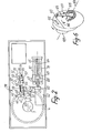
- FIGS. 1 to 6 correspond to a state of rest of the machine, that is to say to a state prior to the tensioning of a section of hose corresponding to an upright or across the racket.
- Figure 1 there is shown schematically in broken line a racket 1 and in broken line a hose 2, which, for example, the machine according to the invention is ready to tension a section corresponding to an amount.
- the machine comprises means 3 adjustable on the one hand in order to adapt to all the shapes and dimensions of racket, and thus make it possible to make the best use of the wide possibilities of the tensioning system. which will be described later, and on the other hand to allow the orientation of the racket 1 as a function of the position of the upright or the cross to be tensioned.
- the means 3 include, on the horizontal upper face 5 of the base 6 of the machine, a horizontal table 4 completely of revolution around an axis 7 fixed relative to the base 6, on which the table 4 is mounted at free rotation around this axis 7.
- the table 4 has the shape of a disc, the upper face 8 est.plane and whose lower face 9 carries, set back towards the axis 7 relative to its circular periphery 10, a skirt continuous 11, internally and externally cylindrical of revolution around the axis 7.
- the cylindrical outer periphery of the skirt 11 carries two identical arms, respectively 12 and 13, essentially vertical and forming above the upper face 8 of the table 4 a projection of identical height, for the reasons which will appear further on, each of the arms 12 and 13 is connected to the cylindrical outer periphery of the skirt 11 by a horizontal, radial rim, such as 14, which on the one hand keeps the arm at a distance from the periphery 10 and on the other hand, being located at a distance from the face 9, also clears the zone of the latter situated between the cylindrical outer periphery of the skirt 11 and the periphery 10.
- each of the arms 12 and 13 carries a half cradle in the form of a horizontal crescent, respectively 15 and 16, the two half cradles 15 and 16 whose concavities face each other substantially resume the form of two opposite zones of the frame of a racket so as to be able to carry such a frame by said zones thereof.
- the two half-cradles 15 and 16 have coplanar horizontal upper faces, respectively 17 and 18, and each has a plurality of vertical orifices, respectively 19 and 20, distributed on its upper face to allow mounting on that -this, in the most appropriate positions taking into account the shape and dimensions of the frame of a racket to be strung, of horizontal jacks, such as respectively 21 and 22, capable of bearing on the outer periphery of the frame of the racket to immobilize it on the assembly constituted by the half-cradles 15 and 16; in addition, in view of this immobilization is provided in the concavity of each half-cradle, in diametrically opposite positions with respect to the axis 7 and projecting above the faces 17 and 18, a hook, respectively 23 and 24 , capable of being supported centrifugally on the inner periphery of the racket frame; for this purpose, each of the hooks 23 and 24 is adjustable in a radial direction, relative to the corresponding half-cradle, by means of a
- the two half-cradles 15 and 16 are also mounted on the upper ends of the arms 12 and 13, respectively by means allowing their adjustment. in position in the same radial, horizontal direction.
- FIG. 3 illustrates the arm 12 to which the arm 13 is identical.
- FIG. 3 shows a view of the arm 12 in a radial direction, towards the axis 7; it appears that the arm 12 has upward a flat, horizontal upper face 27 inside which is arranged a dovetail groove 28, horizontal, radially oriented; additionally, the half-cradle 15 has a flat, horizontal lower face 29, suitable for resting by one of its zones on the upper face 27 of the arm 12, and a rib 30 oriented radially, horizontally, and forming under the face 29 a projection whose dovetail profile is complementary to that of the groove 28; inside this rib 30 is arranged a channel 31 inside which can slide a rod 32 integral with the lug 23 in the concavity of the half-cradle 15 and carrying at the level of the convexity thereof the button softness 25, able to be screwed more or less on the rod 32, by rotation, to adjust the position of the lug 23 relative to the half-cradle 15.
- the half-cradle 15 can slide in a horizontal, radial direction, on the horizontal upper face 27 of the arm 12, to allow immobilization in a position best suited to the shape and dimensions of the frame of the racket to be strung
- the arm 12 is designed as a clamp and has for this purpose a vertical slot 33 passing right through it along a plane including the axis 7 and the axis of the split of the groove 28, the slot 33 originating at the bottom of this groove and extending over most of the height of the arm 12;
- this slot 33 defines at the upper part of the arm 12 two jaws, respectively 34 and 35, each of which corresponds to one of the sides of the groove 28; immobilization at will of the rib 30 in the groove 28 is ensured by tightening the two jaws 34 and 35, by means of a screw passing through them right through in a direction 36 perpendicular to the mean plane of the slot 33 (this screw has not been shown); it will be noted that, given the arcuate shape of the groove 28 and of the rib 30,
- the machine comprises, in a zone always situated outside the cradle constituted by the two half-cradles 15 and 16, that is to say outside the table 4, means d anchoring 37 for the hose, which are carried by an assembly 38 for tensioning this hose which will be described later.
- a rotation of the table 4 around its axis 7 makes it possible to present the racket successively in the positions, vis-à-vis the anchoring means 37 and the tensioning assembly 38, the most suitable for the successive stringing respectively of each upright and of each crosspiece;
- the most suitable position for stringing an upright or a crosspiece corresponds to a position where the section of hose to be tensioned is immobilized in a first zone of the racket frame, free to slide relative to a second zone thereof, and temporarily secured to the anchoring means 37 beyond this second zone relative to the first, with a shape as close to the rectilinear shape as possible.
- braking means 39 which will now be described more particularly with reference to FIG. 2.
- braking means 39 are manually controlled by a handle 40 situated above the face 5 of the base 6 and movable in rotation about a vertical axis relative to the latter, between three notched positions corresponding respectively to total freedom of the table 4 rotating around the axis 7, to a soft braking position allowing manual rotation of the table 4 around the axis 7 with reduced effort, for reasons of working convenience, and a position d firm immobilization of the table 4 relative to the base 6, during a tensioning operation.
- the braking means 39 are illustrated in FIG. 2 in the first of these three positions.
- the braking means 39 comprise a horizontal lever 42 articulated at one of its ends around a vertical axis 41 fixed relative to the base 6 of the machine and disposed relative to the axis 7 of such that, in its three positions corresponding to the three notched positions of the handle 40, the lever 42 is oriented along a cord of the cylindrical inner periphery of the skirt 11 of the table 4, at a level slightly lower than the lower level of this skirt.
- the lever 42 At its second end, curved upwards and passing through the horizontal upper wall 44 of the base 6 via a slot 45 in the latter, the lever 42 carries a shoe 43 placed opposite the cylindrical inner periphery of the skirt 11; the application of the pad 43 against this inner periphery results, as a function of the pressure with which it takes place, by gentle or vigorous braking of the table 4.
- the lever 42 carries on the one hand an anchoring point 45bfor one end of a coil spring 46 whose other end is connected to a point 47 fixed relative to the base 6, in a position such that this spring 46 applies to the lever 42 a constant elastic traction tending to make it pivot about the axis 41 in the direction of an application of the pad 43 against the cylindrical inner periphery of the skirt 11 of the table 4, and on the other hand a vertical lug 48 engaged in an oblong slot 49 of a horizontal link 50 connecting between the lever 42 and a cam 51 integral in rotation with the handle 40 around a vertical axis 52, inside the base 6 ; the rod 50 is articulated on this cam 51, at one of its ends, opposite its end carrying the light 49, around a vertical axis 53 eccentric relative to the axis 52.
- the cam 51 is located on the same side of the lever 42 as the zone of the cylindrical inner periphery of the skirt 11 against which the shoe 43 must be applied, with respect to this shoe 43, and the operation of the braking means 39- is the following.
- the axis 53 is located between the axis 52 and the lever 42 and the link 50 applies to the lug 48, then in contact with the end of the lumen 49 closest to the axis 53, a thrust keeping the shoe 43 at a distance from the cylindrical inner periphery of the skirt 11;
- this first position corresponds to the engagement, in a first notch 54 of the otherwise circular periphery of the cam 51, of a roller 55 which suitable means tend to resiliently approach the axis 52, centers the periphery of the cam 51.
- Appropriate means 59 are provided to allow adjustment of the length of the rod 50 so that each of the three notched positions of the cam 51 effectively corresponds to one of the positions of the shoe 43 defined above; the movement of the shoe 43 accompanying the rotation of the cam 51 in the direction of the arrow 56 is shown diagrammatically by a arrow 60 in FIG. 2.
- FIG. 2 shows preferred means for imparting to the anchoring means 37, in accordance with the invention, a translational movement substantially parallel to the mean plane of the racket immobilized on the two half-cradles 15 and 16, this movement resulting in the tensioning of a section of the hose.
- these means comprise an electric motor 62, the output shaft of which is engaged, if necessary by means of a set of reduction gears 63, with a screw 64 which it rotates, at will in one direction or the other, about its horizontal axis 65 oriented in the direction of translation of the desired anchoring means 37 (this direction is that of arrow 66 in FIG. 1 and of arrow 67 in FIG. 2, these arrows indicating the direction of translation of the anchoring means 37 corresponding to an increase in the tension of the hose).
- the thread of the screw 64 is engaged with a nut 68 which in turn is fixed in rotation relative to the base 6 of the machine, so that the rotation of the screw 64 respectively in one direction or the other results in a translation of the nut 68 parallel to the axis 65, respectively in one direction or the other.
- This nut 68 is integral with a carriage 69 guided in translation parallel to the axis 65 relative to the base 6, for example by means of two rectilinear, fixed slides, 70 and 71 parallel to this axis 65; the slides 70 and 71 are for example defined by rectilinear rods around which slide complementary sleeves of the carriage 69, which are advantageously lined internally with any material improving the sliding.
- the carriage 69 integrally carries a casing 72 which itself carries anchoring means 37; this casing 72 passes through the upper wall 44 of the base 6 via an oblong slot 73 selcn a direction parallel to that of the axis 65, so as to allow the movement of the assembly formed by the carriage 69 and the casing 72 in this direction following the rotation of the screw 64; advantageously, the area of the light 73 released when the casing 72 occupies a determined position is obscured by a shutter sliding along the wall 44 integrally with the carriage 69.
- the casing 72 has the dual role of transmitting the translational movement of the carriage 69 to the anchoring means 37, and of protecting the means of comparison of the instantaneous tension of the hose with a predetermined adjustable tension.
- the casing 72 comprises two vertical cheeks 74 and 75, mutually parallel and parallel to the direction of movement of the carriage 69 of which they are directly integral through the lumen 73, and a cover 76 removed from FIGS. 4 and 5.
- the two cheeks 74 and 75 carry bearings, respectively 78 and 79, defining an axis of rotation 77, horizontal and situated in a plane perpendicular to the direction of movement of the carriage 69, for a shaft 80 for the essential cylindrical of revolution around this axis 77.
- This shaft 80 crosses the cheek 74 from side to side, and carries in its zone situated outside the interval between the two cheeks the means 37 for anchoring the hose.
- These means 37 are designed such that the tensioning of the hose by translation of the assembly 38 in the direction of the arrow 66 tends, by reaction, to rotate the integral assembly formed by these means 37 and the shaft 80 around the axis 77, with respect to the cheeks 74 and 75, in the direction of the arrow 81 in FIG. 5.
- the means 37 consist of a self-tightening clamp comprising a jaw 82 integral with the axis 80 and a jaw 83 articulated on the jaw 82, these two jaws jointly defining a periphery 84 slightly frustoconical of revolution around the axis 77 for receiving the winding hose and, between them, a slot 85 able to receive a strand of the hose and to immobilize it by pinching, because the winding on the periphery 84 results in a tightening of the jaws.
- the periphery 84 Along its upper generatrix, which corresponds to an area of the jaw 82, the periphery 84 carries two neighboring nipples 86 defining between them a precise position of the area of the hose 2 wound around the periphery 84 to ensure the clamping of the clamp .
- the shaft 80 carries down a flat 87 against which is secured an end 88 flattened by a spiral spring 89, describing at mins a portion of turn around the cylindrical periphery of the shaft 80 and comprising a second flat end 90 abutting against the periphery of a roller 91 mounted in free rotation, about its axis 92, parallel to the axis 77, on the "cheek 74; the spring 89, the flat 87 and the roller 91 are arranged such that the spring tends to apply to the shaft 80 an elastic return in the opposite direction to the direction of the arrow 81 when the tensioning of the hose by displacement of the assembly 38 in the direction of arrow 66 tends to cause joint rotation of the anchoring means 37 and of the shaft 80 in the direction of this arrow 81.
- Means other than a spiral spring 89 could be used to force the shaft 80 to react to the action of the tensioned hose, but it will be noted that a spiral spring such as 89 has the advantage of being deformed linearly as a function of a torque of axis 77 which is imposed on it, which means in other words, since the effect of the tension of the hose and that of the spiral spring 89 is balanced at all times, that the instantaneous value of the rotation of the anchoring means 37 about the axis 77 with respect to a position corresponding to a zero tension of the hose and a zero tension of the spiral spring 89 is a linear function of the instantaneous value of the tension of the hose, which facilitates the display of the predetermined voltage to be established therein, as will be described later.
- the shaft 80 carries integrally, downwards, near the cheek 75, a member 95 including an edge 96, oriented upstream taking into account the direction of the arrow 81, is applied against the stop 93 when the spring tension is zero, and a second edge 97 of which, oriented downstream taking account of the direction of the arrow 81, is applied against the stop 94 when the tension of the spiral spring 89 is maximum, which corresponds to a maximum voltage applicable to a hose by means of the machine according to the invention, that is to say for example to an effort of thirty kilos.
- the member 95 is partially delimited, at its lower part, by an edge 98 of revolution around the axis 77 and carrying a gear toothing, complementary to that of a pinion 99 mounted for rotation on the plays 75 around an axis 100 parallel to axis 77; the reduction between the member 95 and the pinion 99 is significant, so that the rotation of the member 95 between the two stops 93 and 94 results in a rotation of the pinion 99 about the axis 100 on an angle also as close as possible to three hundred and sixty degrees, in a direction indicated by the arrow 101 in FIG. 5 when the shaft 80 rotates in the direction of the arrow 81, the member 95 naturally rotating in the same direction as the shaft 80 as indicated by arrow 102 in FIG. 5.
- the pinion 99 integrally carries a radial arm 103 whose radius is as large as possible taking into account its possibilities of rotation at inside the cover 76 of the assembly 38.
- this arm 103 carries towards the cheek 74 a rim 104 parallel to the axis 100 and, at the extremity of this rim 104 closest to the cheek 74, it is ie between the arm 103 and this cheek 74, a plate 105 in return towards the axis 100, parallel to the arm 103; this plate 105 constitutes a flag testifying to the instantaneous position of the arm 103 in rotation about the axis 100, that is to say of the instantaneous position of the shaft 80 around the axis 77, that is to say also the instantaneous tension of hose 2.
- Various means can be provided for detecting this instantaneous position of the plate 105, such as for example opto-electronic proximity detectors, a set of two high frequency induction coils arranged on either side of the forced passage of the plate 105 when the arm 103 rotates about the axis 100, the plate 105 or other equivalent means then being designed in the most appropriate manner as a function of these detection means.
- this wafer 105 is made of a material capable of constituting a magnetic screen, it that is to say in soft iron, the arm 103 being in turn made of a non-magnetic material.
- the cheek 74 is traversed right through by a shaft 108 which is essentially cylindrical of revolution around the axis 106, and comprises to facilitate the rotation of this shaft 108 around the axis 106 a bearing 107 .
- the shaft 108 integrally carries a graduated button 109 allowing display, facing a reference 110 affixed on the cheek 74, the tension which it is desired to impose on the hose (see also FIG. 1).
- the position of the button 109 illustrated in FIGS. 4 to 6 corresponds to the display of a zero value of this voltage.
- the shaft 108 Moreover integrally carries a radial disc 111, situated between the cheek 74 and the forced passage of the plate 105 during its rotation around the axis 100, the respective spokes of the disc 111 around the axis 106 and of the arm 103 around the axis 100 being substantially adjacent.
- the disc 111 carries a flexible blade switch 112 controlling the operation of the motor 62, closing the power supply circuit thereof when it is subjected to the action of a magnetic field applied opposite the face of the disc 111 on which it is fixed, to cause the operation of the motor 62 in the direction of drive of the carriage 68 in the direction of the arrow 67, and to open this circuit and stop the motor 62 as instantly as possible when the action of the magnetic field ceases.
- This magnetic field is applied to the flexible blade switch 112, when the plate 105 is not located opposite it, by a permanent magnet 113 carried by an arm 114 radial with respect to the axis 106, and located between the respective compulsory passages of the plate 105 and of the arm 103 during the rotation of the latter around the axis 100.
- the arm 114 is mounted for rotation about the axis 106 relative to the shaft 108, but it is resiliently recalled by a spring 115, in the opposite direction to the direction of an arrow 116 corresponding to the rotation of the integral assembly 111-button disc 109 in the direction of an increasing voltage display, this arrow 116 being in the same direction as arrow 101, against a stop 117 adjustable so that, when the arm 114 is in contact with this stop 117 under the action of the spring 115, the magnet 113 is placed directly opposite the flexible blade switch 112.
- the tensioning of a section of the hose 2 corresponding for example to an upright, as illustrated in FIG. 1, is carried out as follows, the hose being integral with the frame of the racket in its zone the further from the anchoring means 37, depending on the case, definitively for example by knotting or temporarily by means of a flying clamp or a clamp 118 integrated into the machine as will be described below, and free to slide relative to the frame of the racket in its zone closest to the anchoring means 37.
- the anchoring means are fixed 37 a zone of the hose located outside the frame of the racket, in the example illustrated by winding this zone over a few turns around the periphery 84 of the anchoring means 37 and then engaging a zone of the hose close to its zone wound between the two jaws 82 and 83 where it is immobilized by clamping due to the winding.
- Cn then displays by means of the button 109 the voltage to be applied to the section of the intended hose, in the case of the preferred example, illustrated by rotation of the button 109 in the direction of the arrow 116 at an angle proportional to the tension to be established, relative to the position of this button corresponding to the display of a zero voltage.
- the operator then starts the motor 62, by closing a switch 130 also inserted in the supply circuit thereof, to cause a movement of the carriage 69 in the direction of the arrow 67, and jointly a displacement of the tensioning assembly 38, including the anchoring means 37, in the direction of the arrow 66.
- this rotation which takes place in the direction of the arrow 81, is accompanied by a rotation of the arm 103 and of the plate 105 in the direction of the arrow 101, so that the plate 105 progressively approaches of the flexible blade switch 112 and of the magnet 113 always placed opposite one another, then, when the voltage displayed by means of the button 109 is reached, is interposed between these elements 112 and 113 , which causes on the one hand the opening of the power supply circuit of the motor 62, and on the other hand, by a system of preferably electronic relays, the realization of which is within the domain of human knowledge.
- the hose relaxes while the assembly 38 remains stationary, which results in a rotation of the shaft 80 and of the elements which are integral therewith, around the axis 77, in opposite direction of axis 81; this rotation results in releasing the flexible blade switch 112 and the magnet 113 from the action of the wafer 105, which restarts the motor 62 to start to drive the carriage 69 in the direction of the arrow 67, and the tensioning assembly in the direction of arrow 66, until the displayed voltage is reached again, the plate 105 then again interposing between the elements 112 and 113 to cause the abrupt stop of the motor 62 ; this process can be repeated automatically; when a long time elapses between two successive restartings of the motor 62, it is considered that the tension of the hose section is stabilized; we then immobilize with respect to the frame the area of this section initially mounted to slide relative to the latter, for example by means of a flying clamp or of the clamp 118 which will be described later, then the hose
- FIG. 1 Various means can be used to ensure the temporary immobilization of a zone of the hose relative to the frame of the racket, but in FIG. 1 is shown a clamp system specially adapted to the adjustment possibilities of the two half-cradles 15 and 16 according to a very wide range of shapes and dimensions of racket frames.
- This clamp system 118 comprises a clamp proper 119, known in itself, free to slide vertically and in rotation in a vertical sleeve 120 which, according to the invention can be brought then immobilized extremely quickly in any position on the table 4.
- the sleeve 120 is carried integrally by a base 121 capable of sliding radially with respect to the axis 7, on the upper face 8 of the table 4, along a free radial member 122.
- the two rods 123 and 124 are integrally connected on the one hand near the axis 7 by a part 125 mounted for free rotation around this axis, relative to the table 4, but immobilized in translation along this axis, and on the other hand near the periphery 10 of the table 4 by a piece 126 overlapping this periphery and comprising, under the rim defined over the entire periphery of the table 4 by the area of the face 9 of that -this located outside of the skirt 11, two claws 127 and 128 immobilizing this part in trans lation parallel to the axis 7 while allowing its translation along the entire periphery 10 of the table 4, completely cleared for this purpose as has been described above, by rotation of the entire member 122 around axis 7.
- the immobilization in the required position is ensured in a single operation, by means of a shoe placed under the base 121 and that a lever 129 makes it possible to press at will against the upper face 8 of the table 4, the member 125 and the claws 127 and 128 preventing the base 121 from moving away from this face 8.
- These accessory provisions include, for example limit switches, provided in the example illustrated to detect the extreme positions of the carriage 69 and cause automatic switching of the direction of rotation of the motor 62 when one of the limit switches is actuated.
- FIGS. 4 and 6 have illustrated, in particular, a safety device preventing a false manual operation of the operator from causing the voltage displayed on the screen to be exceeded. by means of button 109.
- means are provided such that the plate 105 projects, when it is rotated in the direction of the arrow 101, from the position where it is interposed between the magnet 113 and the flexible blade switch 112 does not cause the motor 62 to be restarted in the direction of increasing voltages.
- the arm 114 carrying the magnet 113 is not directly secured to the disc 111 carrying the flexible blade switch 112, but it is brought back elastically by a spring 115 against a stop.
- 117 arranged so as to place the magnet 113 and the flexible blade switch 112 opposite one another; additionally, the arm 103 protrudes the cheek 74, upstream, taking into account the direction of the arrow 101, a stop 131 whose forced passage intersects that of the arm 114, so that the protrusion by the plate 105 of the position where it is inserted between the.
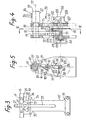
- Figures 7 to 10 show another embodiment of the stringing machine according to the invention.
- the corresponding machine firstly comprises a base 1a of substantially parallelepiped shape. On the upper face 2a of the base, there is a horizontal table 3a which has the shape of a disc, movable in rotation about the axis 4a located in the center thereof.
- These half-cradles are coplanar, and have a rounded ccccave shape facing each other. Their spacing is adjustable so as to adapt to the frame of the racket that has been shown schematically by the broken line 9a, to position it and to immobilize it.
- two hooks 10a and 11a respectively secured to each half-cradle flatten the frame of the racket against them.
- the assembly of the racket, half cradles, arms and discs is movable in rotation about the substantially vertical axis 4a.
- a handle 12a preferably located on the upper face 2a of the base controls a brake which exerts on the disc braking of different intensities. This handle makes it possible to obtain gentle braking, allowing manual rotation of the disc around the axis with reduced effort, and firm immobilization of the disc relative to the base of the machine, during the operation of energizing the hose.
- the hose that is to be tensioned is engaged between the two jaws of an anchoring device 14a secured to a tensioning assembly.
- This assembly comprises a carriage 15a, located inside the base of the machine, controlled in movement by an electric motor also located inside the base.
- the movement of the carriage is a translation which moves the arm 16a, of which the anchoring device 14a is integral, in a slot 17a.
- An electric control 18a allows the starting of the drive motor carriage, stopping and returning to its original position.
- the desired hose tension is displayed on a display button 19a, and the movement away from the anchoring device 14a is stopped when the hose tension reaches the displayed tension.
- the hose tension When the desired hose tension is reached, it should be immobilized temporarily so that it can be manipulated at its end, and put back on again as part of the racket.
- the hose is immobilized from inside the frame. It is then possible to relax the part of the hose located outside the frame, and to handle it.
- a clamp 20a comprising jaws is positioned so that these clamp the hose against the frame of the racket, immobilize it and keep it temporarily under tension.
- two arms 21a and 22a articulated define at their crossing point the positioning of the clamp 20a.
- These arms are free to rotate about vertical axes 23a and 24a, located near the two arms 5a and 6a on which are fixed the two half-cradles which support the racket.
- the two axes 23a and 24a are integrated in the arms 5a and 6a for supporting the half-cradles.
- the length of the arms is slightly less than the distance between the two arms of the support 5a and 6a, so that each of these can be maneuvered over the entire surface of the disc 3a. Their height is slightly different, so that they overlap at their crossing point.
- Each of the two arms has a lumen, respectively 25a and 26a, horizontal, and extending over the greatest length of the arms 21a and 22a.
- the lights At the point of intersection of the two arms, which defines the position of the clamp, the lights define a diamond-shaped orifice.
- the clamp 20a is mounted on an axis which crosses the orifice defined by the crossing of the two lights and which makes it possible to position it.
- the lower arm that is to say in the case of FIG. 7, the arm 21a is kept in its rotational movement by a finger integral with the latter which runs through a groove 27a dug in the disc.
- This groove has a substantially circular shape, centered on the axis of rotation of the arm 21a.
- the finger and the groove are more particularly shown in FIG. 8.
- the finger has a vertical part 28a, and a horizontal part 29a parallel to the direction of the largest dimension of the arm 21a.
- the groove which receives the finger has a section corresponding to the shape of the latter, and the finger has in its upper part a horizontal part 30a which bears on the upper face of the groove. The movement of the rotating arm is however permitted by the circular shape of the groove.
- the movement of the arms around their respective axes makes it possible to move the clamp in a substantially horizontal plane, and to position it at any point defined by the point of intersection of the two slots in each arm.
- Figures 9 and 10 are more particularly related to the clamp, and the mounting thereof on the two arms.
- the clamp has several degrees of freedom, first of all it can move in the horizontal plane by displacement of the two arms, it can also be moved in height as well as in rotation on itself.
- the clamp 20a firstly has two jaws, a fixed jaw 31a, and a movable jaw 32a. Each of these jaws has teeth 33a, located horizontally, in its upper part. The teeth of each of the jaws are respectively opposite one another. Their spacing corresponds to the spacing of the hoses on the racket, so that the teeth can be interposed therebetween.
- the jaws are secured by screwing in their lower part, and the lower end 34a of the movable jaw has been slightly bevelled on its lower face, at the level of its assembly with the fixed jaw. This beveling slightly spreads the movable jaw relative to the fixed jaw, and their respective interior surfaces form a V of small opening inside which the hose 35a can be introduced.
- the clamping of the two jaws is obtained by pulling the movable jaw against the fixed jaw, and by playing on the elasticity of this movable jaw.
- the device which allows the tightening will be described later.
- the assembly of the two jaws can slide vertically along a guide plate 36a. This vertical sliding makes it possible to raise the jaws of the clamp and to engage them on either side of the hose to be immobilized.
- the guide plate 36a has a lumen 40a which opens onto each of the two largest faces of the plate 36a.
- This light has a substantially rectangular shape, and its largest dimension is oriented vertically. Through this light, slides a part 37a of substantially rectangular section and width slightly less than the width of that which passes through the jaw 31a through the hole 39a.
- this part is secured to the movable jaw by means of a screw 38a.
- the part 37a can move vertically along the lumen 40a, causing in its movement the movable jaw and the fixed jaw.
- the length of the light is determined so that in the low position the clamp is below the level of the hoses symbolized by the dashed line 41a, and that in the high position the hose to be immobilized penetrates inside the jaws. It should be noted that in this case any hoses transverse to the hoses to be immobilized are positioned between the teeth 33a of the two jaws.
- the part 37a also comprises a rounded part 41a on which a handle 42a takes hold, the role of which will be described later.
- the assembly formed by the two jaws of the clamp, and the plate 36a is secured by an ax l 43a, around which this assembly can pivot.
- This axis is substantially vertical, and passes through a diamond-shaped orifice defined by the crossing of the two slots 25a and 26a respectively of the two arms.
- the axis of rotation 43a is composed of two parts 45a and 46a assembled by screwing 47a.
- the part 46a comprises at its lower end a head 44a of which the bearing surface is in contact with the lower surface of the lower arm 21 a. At its upper end, this part 46a comprises a thread screwed into a coaxial tapped hole in part 45a, so as to assemble these two parts.
- a washer 48a is interposed on the part 46a of the axis between the two arms. This washer avoids the friction of the two arms one on the other.
- the non-threaded length of the part 46a of the axis corresponds substantially to the height of the two arms, and of the washer 48a.
- the diameter of the non-threaded part is substantially equal to the width of the slots 25a and 26a respectively of the two arms 21a and 22a.
- the upper part 45a of the axis 43a is coaxial with the part 46a, and comprises at its upper end a lug 49a, offset with respect to the axis of the two parts 45a and 46a of the axis of rotation.
- This lug 49a comprises a substantially flat part, located near the axis, on which is fixed, for example by screwing 50a, the support plate 36a. This screwing 50a therefore performs the assembly of the support plate 36a with the axis of rotation 43a.
- the diameter of the upper part 45a of the axis of rotation is slightly greater than the diameter of the unthreaded length of the part 46a.
- a sleeve 51a is mounted in vertical sliding on the part 45a of the axis of rotation 43a.
- This socket has an inside diameter substantially equal to the outside diameter of the part 45a. In its lower part, it has a shoulder 52a which comes to bear on the upper surface of the upper arm 22a.
- This socket laterally has two axes 53a and 54a which are substantially horizontal, diametrically opposite, coaxial and projecting with respect to the vertical exterior surface of the socket 51a.
- a U-shaped stirrup 55a pierced on each of its wings with a substantially horizontal hole with a diameter substantially equal to the diameter of the axes 53a and 54a is articulated in rotation relative to the bushing around these horizontal axes.
- a handle 42a makes it possible to place the clamp in position relative to the hose to be immobilized and to secure it.
- This handle firstly comprises an end of known shape, not shown in FIG. 10 which allows it to be easily manipulated.
- the handle At its other end located on the side of the clamp, the handle has a form of yoke in which the clamp 37a is housed.
- a horizontal axis of articulation crosses the handle right through, and the part 37a, which allows the rotation of the handle relative to this part 37a in a substantially vertical plane.
- a second axis 57a, parallel to the axis 56a crosses the part of the handle which has a form of yoke from side to side.
- a stud 58a is fixed on the second axis 57a, perpendicular thereto, and substantially in the middle. This stud 58a can therefore pivot with the horizontal axis 57a.
- the end 59a of the stud 58a is threaded, and enters a hole 60a drilled in the upper part of the stirrup 55a. This hole 60a is positioned so that the pin 58a can slide freely in it during the movement of the handle.
- a nut 61a screwed onto the threaded part of the stud 58a makes it possible to limit the stroke of the latter in the hole 60a, by resting on the upper face of the stirrup.
- the handle When the handle will be actuated downward, the stud 58a slides in the hole 60a of the stirrup 55a until the nut 61a abuts against the upper bearing face 62a of the stirrup.
- the handle exerts a slight pressure on the sleeve 51a, which by means of its shoulder 52a exerts a slight pinch between the two arms 2la and 22a.
- the handle 42a and the sleeve 51a are articulated relative to each other by the axes on the one hand 57a, and on the other hand 53a and 54a of the sleeve. Following the movement of the handle causes it to pivot relative to the axis 57a, and therefore a rise in the axis 56a.
- This axis drives in its movement the part 37a as well as the two jaws 31a and 32a of the clamp.
- the ascent of the two jaws of the clamp stops when the upper face of the part 37a abuts on the upper end 63a of the lumen 40a.
- the height at which the two jaws of the pliers, as well as the part 37a abut is determined so that the jaws of the pliers, and more particularly its teeth 33a rise to the level of the height 41a, c '' ie at the level of the hose to be immobilized.
- the two axes 56a and 57a pivot relative to each other, the axis 56a exerts an upward traction on the axis 43a, and the axis 57a exerts a thrust on the socket 51a via the stirrup 55a.
- This third part of the movement therefore strongly clamps the two arms 21a and 22a, and immobilizes them relative to one another. Since these arms pivot around axes 23a and 24a integral with the disc 3a, the two arms and the clamp are immobilized relative to the disc.
- the axis 43a around which the clamp can pivot is immobilized by the pinching of the two arms 21a and 22a, since this axis intervenes in the pinching.
- a boss 65a comes into contact with the two zones 66a and 67a of the bearing face 36a, which runs along the lumen 40a. This contacting exerts via the part 37a a traction of the movable jaw towards the fixed jaw, and therefore a closing of the latter on the hose to be immobilized.
- the screw 38a which secures the movable jaw with the part 37a makes it possible to adjust the position of this jaw relative to the axis 56a. It is possible by more or less deep tightening of this screw to adjust the spacing of the movable jaw relative to the fixed jaw, and therefore the pinching of the two jaws on the hose. Depending on the diameter of the hose to be immobilized, it will therefore be possible to adjust this screw in order to adapt the clamp to it.
- the pinching of the two arms 21a and 22a can be adjusted in turn by the nut 61a mounted on the stud 58a. Depending on the position thereof, the stud 58a will penetrate more or less deeply into the hole 60a, and the thrust on the sleeve 51a will be more or less significant.
- the surface of the handle in contact with the two zones 66a and 67a has any suitable shape which gives it a stable locking position at the end of its movement. in the low position.
- the handle 42a in fact controls two different clamps, one formed by the head 44a of the axis 43a and the socket 51a, and the other by the two jaws 31a and 32a of the clamp which immobilizes the hose .
- the two pliers have their respective nip setting, that is to say the nut 61a of the stud 58a for the nip of the two arms, and the screw 38a for the nip of the two jaws.
- the final clamping of the two arms 21a and 22a takes place before the final clamping of the hose by the two jaws 31a and 32a.
- the decomposition of the movements is allowed by the offset position of the two axes 56a and 57a, which are located in an approximately horizontal plane when the handle is unlocked, and which are placed in an approximately vertical plane, one above the other when the handle is locked.
- the clamp is brought under the hose to be immobilized, preferably against the frame of the racket, by moving the two arms 21a and 22a.
- the gripper jaws are then oriented parallel to the hose to be immobilized.
- the two arms tooth the intersection defines the position of the clamp in a horizontal plane are first of all slightly pinched, the jaws of the clamp are raised at the level of the hose to be immobilized, then the two arms are strongly pinched and the jaws are closed. It is naturally enough to unlock the handle by lifting it to release the clamp in its different degrees of freedom.
Landscapes
- Health & Medical Sciences (AREA)
- General Health & Medical Sciences (AREA)
- Physical Education & Sports Medicine (AREA)
- Tension Adjustment In Filamentary Materials (AREA)
- Clamps And Clips (AREA)
- Supports For Pipes And Cables (AREA)
Applications Claiming Priority (2)
| Application Number | Priority Date | Filing Date | Title |
|---|---|---|---|
| FR8004385A FR2475908A2 (fr) | 1980-02-18 | 1980-02-18 | Perfectionnements a la machine a corder les raquettes |
| FR8004385 | 1980-02-18 |
Publications (2)
| Publication Number | Publication Date |
|---|---|
| EP0034688A2 true EP0034688A2 (de) | 1981-09-02 |
| EP0034688A3 EP0034688A3 (en) | 1981-11-11 |
Family
ID=9239070
Family Applications (1)
| Application Number | Title | Priority Date | Filing Date |
|---|---|---|---|
| EP80401621A Withdrawn EP0034688A3 (en) | 1980-02-18 | 1980-11-13 | Machine for stringing rackets |
Country Status (3)
| Country | Link |
|---|---|
| US (1) | US4376535A (de) |
| EP (1) | EP0034688A3 (de) |
| FR (1) | FR2475908A2 (de) |
Cited By (4)
| Publication number | Priority date | Publication date | Assignee | Title |
|---|---|---|---|---|
| FR2551352A1 (fr) * | 1983-08-31 | 1985-03-08 | Morel Jacques | Appareil a corder les raquettes |
| US6162139A (en) * | 1999-04-26 | 2000-12-19 | Deuce Industries Ltd. | String tensioning device |
| EP1486235A1 (de) * | 2002-02-25 | 2004-12-15 | Akifumi Nakane | Neubesaitungsvorrichtung |
| FR3027809A1 (fr) * | 2014-10-31 | 2016-05-06 | Babolat Vs | Systeme de blocage de cordes pour une machine a corder des raquettes et machine a corder comprenant un tel systeme |
Families Citing this family (15)
| Publication number | Priority date | Publication date | Assignee | Title |
|---|---|---|---|---|
| US4846474A (en) * | 1987-08-17 | 1989-07-11 | Chiang Chinn Chann | Swivel glide bar rail table for a racquet stringing machine |
| US5269515A (en) * | 1993-04-29 | 1993-12-14 | Chu David T | Machine for stringing game racket |
| US5733212A (en) * | 1996-10-08 | 1998-03-31 | Wise U. S. A., Inc. | Electronic racket stringing machine |
| CN1299097C (zh) | 1998-06-22 | 2007-02-07 | 西铁城时计株式会社 | 带方位计的电子设备及在该电子设备中的方位测量方法 |
| US6093121A (en) * | 1998-10-27 | 2000-07-25 | Bishop; Jonah C. | Swivel clamp for racket stringing |
| JP2001314532A (ja) * | 2000-05-02 | 2001-11-13 | Akira Tsuchida | テニスラケット等のガット張り装置におけるガットクランプ機構 |
| AU2001281625A1 (en) * | 2000-08-03 | 2002-02-18 | Xception Sports Technologies License Ag | Device and method for measuring rackets |
| TW493457U (en) * | 2001-08-10 | 2002-07-01 | Ding-Wei Ju | Device for pulling thread for racket |
| US6837811B1 (en) * | 2004-03-16 | 2005-01-04 | Pao-Chang Wu | String pulling device for racket stringer |
| US7153226B1 (en) * | 2005-12-27 | 2006-12-26 | Erik Bernard Van Der Pols | String-pulling device of a racket stringing apparatus |
| US7980968B1 (en) * | 2010-06-17 | 2011-07-19 | Elding Ind. Co., Ltd. | Stringing device of a racket stringing machine |
| US8206249B1 (en) * | 2011-04-08 | 2012-06-26 | Herbert H. Wise | Electronic racquet stringing machine |
| US9236778B2 (en) * | 2012-11-06 | 2016-01-12 | GM Global Technology Operations LLC | Generator attachment assembly and method |
| US20150133243A1 (en) * | 2013-11-11 | 2015-05-14 | Vaclav Zdrazila | Dual Stringing Tennis Racket Machine and Method |
| CN114100093B (zh) * | 2021-11-09 | 2022-11-01 | 杭州电子科技大学 | 一种羽毛球拍穿线装置 |
Citations (8)
| Publication number | Priority date | Publication date | Assignee | Title |
|---|---|---|---|---|
| DE532947C (de) * | 1928-10-17 | 1931-09-07 | Wiener Edelsaitenfabrik G M B | Einrichtung zum Bespannen von Tennisschlaegern mit Saiten |
| US2154870A (en) * | 1936-06-10 | 1939-04-18 | Edmundo H Serrano | Apparatus for stringing tennis rackets |
| FR1553389A (de) * | 1967-02-21 | 1969-01-10 | ||
| US3441275A (en) * | 1967-03-03 | 1969-04-29 | Franklin W Held | Racket stringer |
| BE733867A (de) * | 1968-05-31 | 1969-11-03 | ||
| US3918713A (en) * | 1974-03-15 | 1975-11-11 | Bernard Kaminstein | Racket stringing machine |
| FR2327803A1 (fr) * | 1975-10-13 | 1977-05-13 | Babolat Maillot Witt | Machine a corder les raquettes a reglage electronique |
| EP0026008A1 (de) * | 1979-09-04 | 1981-04-01 | FISCHER INDUSTRIES personenvennootschap met beperkte aansprakelijkheid | Vorrichtung zum Bespannen von Schlägern |
Family Cites Families (3)
| Publication number | Priority date | Publication date | Assignee | Title |
|---|---|---|---|---|
| US1969826A (en) * | 1929-03-19 | 1934-08-14 | Dunlop Rubber Company Limited | - means for stringing tennis rackets with strings |
| US2067512A (en) * | 1934-10-10 | 1937-01-12 | Roy Sterns Company | Apparatus for stringing tennis rackets |
| US2114216A (en) * | 1937-05-18 | 1938-04-12 | Doll Air Stringer Of America I | Racket stringing apparatus |
-
1980
- 1980-02-18 FR FR8004385A patent/FR2475908A2/fr active Pending
- 1980-11-13 EP EP80401621A patent/EP0034688A3/fr not_active Withdrawn
- 1980-12-18 US US06/217,891 patent/US4376535A/en not_active Expired - Fee Related
Patent Citations (8)
| Publication number | Priority date | Publication date | Assignee | Title |
|---|---|---|---|---|
| DE532947C (de) * | 1928-10-17 | 1931-09-07 | Wiener Edelsaitenfabrik G M B | Einrichtung zum Bespannen von Tennisschlaegern mit Saiten |
| US2154870A (en) * | 1936-06-10 | 1939-04-18 | Edmundo H Serrano | Apparatus for stringing tennis rackets |
| FR1553389A (de) * | 1967-02-21 | 1969-01-10 | ||
| US3441275A (en) * | 1967-03-03 | 1969-04-29 | Franklin W Held | Racket stringer |
| BE733867A (de) * | 1968-05-31 | 1969-11-03 | ||
| US3918713A (en) * | 1974-03-15 | 1975-11-11 | Bernard Kaminstein | Racket stringing machine |
| FR2327803A1 (fr) * | 1975-10-13 | 1977-05-13 | Babolat Maillot Witt | Machine a corder les raquettes a reglage electronique |
| EP0026008A1 (de) * | 1979-09-04 | 1981-04-01 | FISCHER INDUSTRIES personenvennootschap met beperkte aansprakelijkheid | Vorrichtung zum Bespannen von Schlägern |
Cited By (8)
| Publication number | Priority date | Publication date | Assignee | Title |
|---|---|---|---|---|
| FR2551352A1 (fr) * | 1983-08-31 | 1985-03-08 | Morel Jacques | Appareil a corder les raquettes |
| EP0136245A2 (de) * | 1983-08-31 | 1985-04-03 | MOREL TECHNIC S.à.r.l. | Gerät zum Bespannen von Schlägern |
| EP0136245A3 (en) * | 1983-08-31 | 1985-07-31 | Morel Technic S.A.R.L. | Apparatus for stringing rackets |
| US6162139A (en) * | 1999-04-26 | 2000-12-19 | Deuce Industries Ltd. | String tensioning device |
| EP1486235A1 (de) * | 2002-02-25 | 2004-12-15 | Akifumi Nakane | Neubesaitungsvorrichtung |
| EP1486235A4 (de) * | 2002-02-25 | 2008-07-16 | Akifumi Nakane | Neubesaitungsvorrichtung |
| FR3027809A1 (fr) * | 2014-10-31 | 2016-05-06 | Babolat Vs | Systeme de blocage de cordes pour une machine a corder des raquettes et machine a corder comprenant un tel systeme |
| US9993697B2 (en) | 2014-10-31 | 2018-06-12 | Babolat Vs | System for blocking strings for a racket stringing machine and racket stringing machine comprising such a system |
Also Published As
| Publication number | Publication date |
|---|---|
| US4376535A (en) | 1983-03-15 |
| FR2475908A2 (fr) | 1981-08-21 |
| EP0034688A3 (en) | 1981-11-11 |
Similar Documents
| Publication | Publication Date | Title |
|---|---|---|
| EP0034688A2 (de) | Maschine zum Bespannen von Schlägern | |
| EP0382652B1 (de) | Vorrichtung zum Bespannen eines Tennisschlägers | |
| EP0270419A1 (de) | Handgesteuerte Bandumwicklungsvorrichtung von Stücken, wie namentlich Kabelbäumen | |
| FR2640905A1 (de) | ||
| CA2223864C (fr) | Outil de raccordement d'une fibre a une autre fibre ou a un element de connectique optique par l'intermediaire d'un module de raccordement | |
| WO2003083243A9 (fr) | Mecanisme de tension d'un ressort de compensation pour installation de fermeture ou de protection solaire | |
| CH371373A (fr) | Machine pour enrouler un élément filiforme sur une bobine | |
| FR2460688A1 (fr) | Machine a corder les raquettes | |
| EP0010016B1 (de) | Antriebsmechanismus zur Parallelführung einer Reissschiene auf einem Zeichenbrett | |
| FR2693781A1 (fr) | Dispositif de réglage de la tension d'un câble faisant boucle. | |
| EP0082159B1 (de) | Vorrichtung zum ausrichten und einführen von drahtspeichen in löcher einer speichenradnabe | |
| EP0947661B1 (de) | Einwegarretiereinrichtung für Rolladen | |
| FR2699908A1 (fr) | Pince à géométrie variable pour la prise de bobines en auto-serrage et leur basculement sur 90degré . | |
| WO2001052961A1 (fr) | Barre de controle pour aile de traction avec enrouleur integre | |
| EP0606865B1 (de) | Wandvorrichtung für Lamellenvorhang | |
| CH650752A5 (en) | Manual clamping device | |
| FR2659059A1 (en) | Device for adjusting the speed of a parapent and parapent equipped with such a device | |
| FR2746063A1 (fr) | Dispositif permettant de faciliter le deplacement d'un siege de vehicule automobile vers l'avant de celui-ci | |
| EP0343063A1 (de) | Winde zum Antreiben eines Bandes | |
| FR2547323A1 (fr) | Frein stationnaire pour des broches de filage et de retordage, en particulier des broches creuses | |
| EP1293462A2 (de) | Spulenhalter für Garnaufspulmaschinen | |
| BE1015262A6 (fr) | Ensemble d'eclairage. | |
| FR2534235A1 (fr) | Pince pour la manutention de bobines | |
| EP0166668A1 (de) | Angelwinde mit einer Entkupplungsvorrichtung für die Spule | |
| EP1059228A1 (de) | Tauklemmer |
Legal Events
| Date | Code | Title | Description |
|---|---|---|---|
| PUAI | Public reference made under article 153(3) epc to a published international application that has entered the european phase |
Free format text: ORIGINAL CODE: 0009012 |
|
| AK | Designated contracting states |
Designated state(s): AT BE CH DE IT LU NL SE |
|
| PUAL | Search report despatched |
Free format text: ORIGINAL CODE: 0009013 |
|
| AK | Designated contracting states |
Designated state(s): AT BE CH DE IT LU NL SE |
|
| 17P | Request for examination filed |
Effective date: 19820301 |
|
| RAP1 | Party data changed (applicant data changed or rights of an application transferred) |
Owner name: SNAUWAERT & DEPLA SOCIETE BELGE |
|
| STAA | Information on the status of an ep patent application or granted ep patent |
Free format text: STATUS: THE APPLICATION IS DEEMED TO BE WITHDRAWN |
|
| 18D | Application deemed to be withdrawn |
Effective date: 19831201 |
|
| RIN1 | Information on inventor provided before grant (corrected) |
Inventor name: MUSELET, JACQUES Inventor name: MUSELET, ANDRE |