EP0771931A1 - Safety device for ladder and ladder incorporating the same - Google Patents
Safety device for ladder and ladder incorporating the same Download PDFInfo
- Publication number
- EP0771931A1 EP0771931A1 EP96402323A EP96402323A EP0771931A1 EP 0771931 A1 EP0771931 A1 EP 0771931A1 EP 96402323 A EP96402323 A EP 96402323A EP 96402323 A EP96402323 A EP 96402323A EP 0771931 A1 EP0771931 A1 EP 0771931A1
- Authority
- EP
- European Patent Office
- Prior art keywords
- ladder
- arms
- rope
- post
- pole
- Prior art date
- Legal status (The legal status is an assumption and is not a legal conclusion. Google has not performed a legal analysis and makes no representation as to the accuracy of the status listed.)
- Withdrawn
Links
Images


Classifications
-
- E—FIXED CONSTRUCTIONS
- E06—DOORS, WINDOWS, SHUTTERS, OR ROLLER BLINDS IN GENERAL; LADDERS
- E06C—LADDERS
- E06C7/00—Component parts, supporting parts, or accessories
- E06C7/48—Ladder heads; Supports for heads of ladders for resting against objects
-
- E—FIXED CONSTRUCTIONS
- E06—DOORS, WINDOWS, SHUTTERS, OR ROLLER BLINDS IN GENERAL; LADDERS
- E06C—LADDERS
- E06C1/00—Ladders in general
- E06C1/02—Ladders in general with rigid longitudinal member or members
- E06C1/34—Ladders attached to structures, such as windows, cornices, poles, or the like
-
- E—FIXED CONSTRUCTIONS
- E06—DOORS, WINDOWS, SHUTTERS, OR ROLLER BLINDS IN GENERAL; LADDERS
- E06C—LADDERS
- E06C7/00—Component parts, supporting parts, or accessories
- E06C7/18—Devices for preventing persons from falling
- E06C7/186—Rail or rope for guiding a safety attachment, e.g. a fall arrest system
Definitions
- the present invention relates to a ladder safety device and a ladder equipped with such a device.
- a ladder is used, generally telescopic, which is pressed against the upper part of the post.
- Safety devices for ladders are already known which allow a ladder to be locked to a pole by means of adjustment operations, which are generally long and complicated.
- the present invention aims to provide a device for blocking a ladder against a mast which solves the problems mentioned above.
- This device finds its application in many other fields than that of the maintenance of overhead cables, such as for example the maintenance of trees and more generally any activity in which a ladder must be pressed against a substantially vertical cylindrical support.
- the present invention relates to a safety device for a ladder, characterized in that it comprises in combination two pivoting arms mounted at the top of the ladder, capable of assuming an open position, or rest position, in which they leave between them sufficient space for the passage of a pole and a closed position, or working position, in which these arms are clamped against said pole, a cord connecting said arms to the lower part of the ladder to exert a force on the arms which tends to cause them to close when this rope is pulled down, said rope serving as a lifeline by comprising a self-locking sliding handle to which a harness can be connected or a belt worn by the user of the ladder.
- the user can apply the upper end of the ladder against the post, while the arms are in the open position, after which it suffices to pull on the rope to close the arms around the pole and fix the bottom of the rope to the ladder to ensure the ladder is held in place for the first time.
- the arms in the open position are brought completely onto the face of the ladder which is not applied against the post so as to limit the space requirement of the upper part of the ladder when it is positioned against the pole or against a tree.
- This embodiment is particularly advantageous because it makes it possible to reduce the size of the ladder, which may be advantageous for storing it or for working on a mast located in branches.
- This embodiment also makes it possible to use the ladder against a wall, in the manner of a traditional ladder, without having to disassemble the locking device.
- the arms pass from their open position to their closed position when the rope is pulled towards the lower part of the ladder, while springs, of preferably helical, act on the arms to constantly bring them back to the open position.
- pivoting arms are not likely to move to come against the face of the ladder which is directed against the post when the ladder is positioned.
- the arms are articulated in the vicinity of one of the uprights of the ladder, around a substantially vertical axis when the ladder is in the position of use.
- the rope is connected to each arm at a point on this arm located approximately 10 cm from its pivot axis.
- a slightly curved bearing surface is located substantially at the height of the two arms and allows the ladder to be pressed against the post by centering the latter in the central part of the span d 'support.
- the bearing surface comprises rollers capable of rolling along the post to facilitate the positioning and possibly the deployment of the ladder, the bearing surface already being applied against the post.
- the present invention also relates to a ladder provided with a safety device as described above.
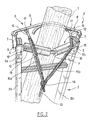
- FIG 1 there is shown a vertical post 1, against which a ladder 2 according to the invention is supported by its upper part 3. A user 4 is climbing to the top of the ladder.
- the ladder comprises a safety device 5 which comprises two tubes of rectangular section 6 each engaged at the top of one of the uprights 2 a , 2 b of the ladder and tightened by collars 6 a , 6 b .
- Sleeves 7 are welded to the outer lateral face of the tubes 6 in a direction such that said sleeves 7 are substantially vertical when the ladder is pressed against the post 1, as seen in FIG. 1.
- Each sleeve 7 receives the vertical branch of an arm 8, able to pivot in said sleeve.
- a pin 9 axially retains each arm in the corresponding sleeve.
- Each arm 8 is thus able to pivot in a substantially horizontal plane, as will be explained with reference to FIGS. 3 to 6.
- Torsion springs are fixed on the one hand to the lower end of each arm, on the other hand to the corresponding tube and ensure the return of the arms to the closed position shown in FIG. 3.
- each arm 8 ends in a curved part, the curvature of which is directed towards the ladder so as to effectively clamp the post 1 by immobilizing it in an area situated substantially at equal distance from the two sleeves 7.
- the safety device 5 also includes a bearing surface 10 which is constituted by a curved bar 11 which is substantially V-shaped, the two branches of which support rollers 12 capable of rotating freely around the bar 11.
- the ends of the bar 11 are welded to the tubes 6.
- the ladder is applied against the post by its bearing surface 10, and more precisely by its rollers 12, which, by being able to roll along the post, facilitate the positioning of the ladder and possibly its deployment avoiding wear of the bearing surface 10 against the post, which is especially advantageous when the post is made of cement.
- Each strand 15 a , 15 b of the rope is guided in an eyelet 18 which is produced on a rod 19 parallel to the curved bar 11, welded at its ends to the two tubes 6 and in its middle to the curved bar 11.
- the safety device is shown with its arms 8 retracted, that is to say that the arms 8 are in the open position and are folded down on the side of the ladder opposite to the post 1.
- the ladder can be applied against the post 1 by its rollers 12, which facilitate the sliding of the upper part of the ladder against the post.
- each arm 8 pivots about 320 ° in the direction of its opening, that is to say, relative to Figure 2 , counterclockwise for the arm corresponding to the amount 2 a and clockwise for the arm corresponding to the amount 2 b .
- each strand 15 a , 15 b of the cord 13 is wound around the vertical branch of the corresponding arm 8.
- the strands 15 a and 15 b wound around the vertical branches of the arms 8 do not overlap, which makes it possible to avoid friction of the rope on itself, friction which could lead to wear of the rope and blockage of the arms 8.
- the arms 8 After having pivoted about half a turn, the arms 8 reach the position shown in FIG. 5.
- the strands 15 a and 15 b of the rope are then fully unwound and stretch between the connecting rod 16 and the corresponding eyelet 18.
- the rods can avoid causing the strands 15 a , 15 b to rub against the post, which is advantageous in particular when it is a post in concrete.
- the user stretches the rope 13 along the ladder and attaches it to the bottom of the ladder.
- the rope can therefore be a little loose, the arms then not being tightly tightened against the post but kept in a position in which they enclose the post against the bearing surface.
- a blocker 20 secured to one of the bars of the ladder, as seen in FIG. 8.
- the blocker 20 prevents the rope from going up but allows it to slide down.
- the ladder is thus applied against the pole with its arms surrounding said pole.
- the user puts on a harness or a belt (not shown) which he connects to a self-locking handle 21, shown in FIG. 7, which is engaged on the rope 13 so as to be able to climb freely along this rope and to hang on said rope when it is pulled down.
- FIG. 7 there is shown in broken lines a mechanism for blocking the self-locking handle on the cord 13.
- the user can climb freely along the ladder, using the rope as a lifeline.
- the rope 13 can then exert maximum torque on the arms 8 because the links 16 and the strands 15 a , 15 b extend substantially perpendicular to the horizontal branches of the arms 8.
Abstract
Description
La présente invention concerne un dispositif de sécurité pour échelle et une échelle équipée d'un tel dispositif.The present invention relates to a ladder safety device and a ladder equipped with such a device.
Pour entretenir des câbles aériens, notamment de lignes électriques ou téléphoniques, il est quelquefois nécessaire d'effectuer des interventions au sommet des poteaux qui supportent ces câbles.To maintain overhead cables, in particular electrical or telephone lines, it is sometimes necessary to carry out interventions at the top of the posts which support these cables.
Lorsque le poteau est un simple mât lisse, on utilise une échelle, généralement téléscopique, que l'on appuie contre la partie supérieure du poteau.When the post is a simple smooth mast, a ladder is used, generally telescopic, which is pressed against the upper part of the post.
Néanmoins, cette opération n'est pas sans présenter certains dangers, et ce, d'autant plus que certains poteaux peuvent s'élever assez haut.However, this operation is not without certain dangers, all the more so since some posts can rise quite high.
On connaît déjà des dispositifs de sécurité pour échelle qui permettent de verrouiller une échelle à un poteau moyennant des opérations de réglage, généralement longues et compliquées.Safety devices for ladders are already known which allow a ladder to be locked to a pole by means of adjustment operations, which are generally long and complicated.
Ces dispositifs ne donnent cependant pas entière satisfaction du fait que leur manipulation n'est pas facile, ce qui incite les utilisateurs d'échelles à ne pas les mettre en oeuvre.However, these devices are not entirely satisfactory since their handling is not easy, which encourages users of ladders not to use them.
Par ailleurs, on connaît les lignes de vie qui sont des cordes auxquelles on peut s'arrimer pour prévenir une chute.In addition, we know the lifelines which are ropes to which we can tie to prevent a fall.
La présente invention vise à fournir un dispositif de blocage d'une échelle contre un mât qui résout les problèmes rappelés ci-dessus.The present invention aims to provide a device for blocking a ladder against a mast which solves the problems mentioned above.
Ce dispositif trouve son application dans de nombreux autres domaines que celui de l'entretien des câbles aériens, comme par exemple l'entretien des arbres et plus généralement toute activité dans laquelle une échelle doit être appuyée contre un support cylindrique sensiblement vertical.This device finds its application in many other fields than that of the maintenance of overhead cables, such as for example the maintenance of trees and more generally any activity in which a ladder must be pressed against a substantially vertical cylindrical support.
La présente invention a pour objet un dispositif de sécurité pour échelle, caractérisé par le fait qu'il comporte en combinaison deux bras pivotants montés à la partie supérieure de l'échelle, aptes à prendre une position ouverte, ou position de repos, dans laquelle ils laissent entre eux un espace suffisant pour le passage d'un poteau et une position fermée, ou position de travail, dans laquelle ces bras sont serrés contre ledit poteau, une corde reliant lesdits bras à la partie inférieure de l'échelle pour exercer sur les bras une force qui tend à provoquer leur fermeture lorsque cette corde est tirée vers le bas, ladite corde servant de ligne de vie en comportant une poignée coulissante auto-bloquante à laquelle peut être relié un harnais ou une ceinture porté par l'utilisateur de l'échelle.The present invention relates to a safety device for a ladder, characterized in that it comprises in combination two pivoting arms mounted at the top of the ladder, capable of assuming an open position, or rest position, in which they leave between them sufficient space for the passage of a pole and a closed position, or working position, in which these arms are clamped against said pole, a cord connecting said arms to the lower part of the ladder to exert a force on the arms which tends to cause them to close when this rope is pulled down, said rope serving as a lifeline by comprising a self-locking sliding handle to which a harness can be connected or a belt worn by the user of the ladder.
On comprend que, grâce à l'invention, l'utilisateur peut appliquer l'extrémité supérieure de l'échelle contre le poteau, alors que les bras sont en position ouverte, à la suite de quoi il lui suffit d'exercer une traction sur la corde pour refermer les bras autour du poteau et de fixer le bas de la corde à l'échelle pour assurer un premier maintien de l'échelle.It is understood that, thanks to the invention, the user can apply the upper end of the ladder against the post, while the arms are in the open position, after which it suffices to pull on the rope to close the arms around the pole and fix the bottom of the rope to the ladder to ensure the ladder is held in place for the first time.
L'utilisateur accroche alors son harnais ou sa ceinture à la poignée auto-bloquante de la ligne de vie et monte sur l'échelle, tandis que la poignée auto-bloquante coulisse le long de la corde qui sert de ligne de vie.The user then hooks his harness or his belt to the self-locking handle of the lifeline and climbs the ladder, while the self-locking handle slides along the rope which serves as a lifeline.
Si, à la suite d'un faux mouvement, l'utilisateur de l'échelle fait une chute ou se trouve en déséquilibre, il exerce alors une traction sur la ligne de vie par l'intermédiaire de son harnais, et il provoque un accroissement des forces de serrage des bras contre le poteau, ce qui a pour effet d'assurer une solidarisation parfaite entre la partie supérieure de l'échelle et le poteau.If, as a result of a false movement, the user of the ladder falls or becomes unbalanced, he then exerts a traction on the lifeline through his harness, and it causes an increase clamping forces of the arms against the post, which has the effect of ensuring a perfect connection between the upper part of the ladder and the post.
Dans un mode de réalisation préféré, les bras en position ouverte sont ramenés complètement sur la face de l'échelle qui n'est pas appliquée contre le poteau de manière à limiter l'encombrement de la partie supérieure de l'échelle lors de son positionnement contre le poteau ou contre un arbre.In a preferred embodiment, the arms in the open position are brought completely onto the face of the ladder which is not applied against the post so as to limit the space requirement of the upper part of the ladder when it is positioned against the pole or against a tree.
Ce mode de réalisation est particulièrement avantageux car il permet de réduire l'encombrement de l'échelle, ce qui peut être intéressant pour la stocker ou pour intervenir sur un mât situé dans des branchages.This embodiment is particularly advantageous because it makes it possible to reduce the size of the ladder, which may be advantageous for storing it or for working on a mast located in branches.
Ce mode de réalisation permet également d'utiliser l'échelle contre un mur, à la manière d'une échelle traditionnelle, sans devoir démonter le dispositif de blocage.This embodiment also makes it possible to use the ladder against a wall, in the manner of a traditional ladder, without having to disassemble the locking device.
Dans un mode de réalisation préféré, les bras passent de leur position ouverte à leur position fermée lorsque l'on tire la corde vers la partie inférieure de l'échelle, tandis que des ressorts, de préférence hélicoïdaux, agissent sur les bras pour les ramener constamment en position ouverte.In a preferred embodiment, the arms pass from their open position to their closed position when the rope is pulled towards the lower part of the ladder, while springs, of preferably helical, act on the arms to constantly bring them back to the open position.
De cette manière, les bras pivotants ne risquent pas de se déplacer pour venir contre la face de l'échelle qui est dirigée contre le poteau au moment où l'on positionne l'échelle.In this way, the pivoting arms are not likely to move to come against the face of the ladder which is directed against the post when the ladder is positioned.
Dans un mode de réalisation particulier de l'invention, les bras sont articulés au voisinage d'un des montants de l'échelle, autour d'un axe sensiblement vertical lorsque l'échelle est en position d'utilisation.In a particular embodiment of the invention, the arms are articulated in the vicinity of one of the uprights of the ladder, around a substantially vertical axis when the ladder is in the position of use.
Ainsi, le mouvement des bras passant d'une position à l'autre s'effectue dans un plan sensiblement horizontal lorsque l'échelle se trouve en position d'utilisation.Thus, the movement of the arms passing from one position to the other takes place in a substantially horizontal plane when the ladder is in the position of use.
De préférence, la corde est reliée à chaque bras en un point de ce bras situé sensiblement à 10 cm de son axe de pivotement.Preferably, the rope is connected to each arm at a point on this arm located approximately 10 cm from its pivot axis.
Dans un mode de réalisation particulier de l'invention, une portée d'appui légèrement incurvée est située sensiblement à la hauteur des deux bras et permet d'appuyer l'échelle contre le poteau en centrant ce dernier dans la partie centrale de la portée d'appui.In a particular embodiment of the invention, a slightly curved bearing surface is located substantially at the height of the two arms and allows the ladder to be pressed against the post by centering the latter in the central part of the span d 'support.
Dans une variante préférée de ce mode de réalisation, la portée d'appui comporte des rouleaux aptes à rouler le long du poteau pour faciliter la mise en place et éventuellement le déploiement de l'échelle, la portée d'appui étant déjà appliquée contre le poteau.In a preferred variant of this embodiment, the bearing surface comprises rollers capable of rolling along the post to facilitate the positioning and possibly the deployment of the ladder, the bearing surface already being applied against the post.
La présente invention a également pour objet une échelle munie d'un dispositif de sécurité tel que décrit ci-dessus.The present invention also relates to a ladder provided with a safety device as described above.
Dans le but de mieux faire comprendre l'invention, on va en décrire maintenant un mode de réalisation donné à titre d'exemple non limitatif en référence au dessin annexé dans lequel :
- la figure 1 est une vue en élévation d'un utilisateur monté sur une échelle selon l'invention appliquée contre un poteau,
- la figure 2 est une vue en perspective de la partie supérieure de l'échelle,
- les figures 3, 4, 5 et 6 sont des vues de dessus de l'échelle au cours de la mise en place des bras autour du poteau,
- la figure 7 est une vue de côté d'une poignée auto-bloquante engagée sur la corde, et
- la figure 8 est une vue de face de la partie inférieure de l'échelle.
- FIG. 1 is an elevation view of a user mounted on a ladder according to the invention applied against a post,
- FIG. 2 is a perspective view of the upper part of the ladder,
- FIGS. 3, 4, 5 and 6 are top views of the ladder during the positioning of the arms around the post,
- FIG. 7 is a side view of a self-locking handle engaged on the rope, and
- Figure 8 is a front view of the bottom of the ladder.
Sur la figure 1, on a représenté un poteau vertical 1, contre lequel une échelle 2 selon l'invention est appuyée par sa partie supérieure 3. Un utilisateur 4 est en train de monter au sommet de l'échelle.In Figure 1, there is shown a
Sur la figure 2, on voit comment l'échelle 2 est agrippée au poteau 1.In Figure 2, we see how the
A sa partie supérieure 3, l'échelle comporte un dispositif de sécurité 5 qui comprend deux tubes de section rectangulaire 6 engagés chacun au sommet d'un des montants 2a, 2b de l'échelle et serrés par des colliers 6a, 6b.At its
Des fourreaux 7 sont soudés sur la face latérale extérieure des tubes 6 dans une direction telle que lesdits fourreaux 7 sont sensiblement verticaux lorsque l'échelle est appuyée contre le poteau 1, comme on le voit sur la figure 1.
Chaque fourreau 7 reçoit la branche verticale d'un bras 8, apte à pivoter dans ledit fourreau.Each
Une goupille 9 retient axialement chaque bras dans le fourreau correspondant.A
Chaque bras 8 est ainsi apte à pivoter dans un plan sensiblement horizontal, ainsi qu'il sera expliqué en référence aux figures 3 à 6.Each
Des ressorts de torsion, non représentés, sont fixés d'une part à l'extrémité inférieure de chaque bras, d'autre part au tube correspondant et assurent le rappel des bras en position fermée représentée sur la figure 3.Torsion springs, not shown, are fixed on the one hand to the lower end of each arm, on the other hand to the corresponding tube and ensure the return of the arms to the closed position shown in FIG. 3.
La branche horizontale de chaque bras 8 se termine par une partie courbée dont la courbure est dirigée vers l'échelle de manière à serrer efficacement le poteau 1 en l'immobilisant d'une zone située sensiblement à égale distance des deux fourreaux 7.The horizontal branch of each
Le dispositif de sécurité 5 comporte également une portée d'appui 10 qui est constituée par une barre incurvée 11 sensiblement en forme de V dont les deux branches supportent des rouleaux 12 aptes à tourner librement autour de la barre 11.The
Les extrémités de la barre 11 sont soudées aux tubes 6.The ends of the
Comme on le voit sur la figure 2, l'échelle est appliquée contre le poteau par sa portée d'appui 10, et plus précisément par ses rouleaux 12, lesquels, en pouvant rouler le long du poteau, facilitent le positionnement de l'échelle et éventuellement son déploiement en évitant l'usure de la portée d'appui 10 contre le poteau, ce qui est surtout avantageux lorsque le poteau est réalisé en ciment.As can be seen in FIG. 2, the ladder is applied against the post by its
On comprend que la forme en V de la barre 11 et les extrémités courbes des bras 8 conduisent au centrage du poteau par rapport à l'échelle.It is understood that the V shape of the
Une corde 13, nouée en 14 de manière à comporter deux brins 15a et 15b, est reliée à chacun des bras 8 par l'intermédiaire de biellettes 16 qui sont chacune articulée sur un axe 17 soudé en dessous de chaque bras, à une distance d'environ 10 cm du fourreau 7 correspondant.A
Chaque brin 15a, 15b de la corde est guidé dans un oeillet 18 qui est réalisé sur une tige 19 parallèle à la barre incurvée 11, soudée à ses extrémités sur les deux tubes 6 et en son milieu à la barre incurvée 11.Each
Dans la position représentée sur la figure 2, on comprend que lorsque l'on tire la corde 13 vers le bas, on provoque le serrage des deux bras 8 autour du poteau 1.In the position shown in FIG. 2, it is understood that when the
Sur la figure 3, le dispositif de sécurité est représenté avec ses bras 8 escamotés, c'est-à-dire que les bras 8 se trouvent en position ouverte et sont rabattus du côté de l'échelle opposé au poteau 1.In FIG. 3, the safety device is shown with its
Dans cette position des bras 8, l'échelle peut être appliquée contre le poteau 1 par ses rouleaux 12, lesquels facilitent le coulissement de la partie supérieure de l'échelle contre le poteau.In this position of the
Pour passer de la position fermée représentée à la figure 2 à la position ouverte de la figure 3, chaque bras 8 pivote d'environ 320° dans le sens de son ouverture, c'est-à-dire, par rapport à la figure 2, dans le sens inverse à celui des aiguilles d'une montre pour le bras correspondant au montant 2a et dans le sens des aiguilles d'une montre pour le bras correspondant au montant 2b.To move from the closed position shown in Figure 2 to the open position of Figure 3, each
Lors de ce pivotement, chaque brin 15a, 15b de la corde 13 s'enroule autour de la branche verticale du bras 8 correspondant.During this pivoting, each
Grâce à la présence des biellettes 16, les brins 15a et 15b enroulés autour des branches verticales des bras 8 ne se chevauchent pas, ce qui permet d'éviter le frottement de la corde sur elle-même, frottement qui pourrait entraîner l'usure de la corde et le blocage des bras 8.Thanks to the presence of the
Une fois l'échelle correctement mise en place, on exerce une traction sur la corde 13, ce qui entraîne le pivotement des bras 8.Once the ladder is correctly positioned, traction is exerted on the
Compte tenu du fait que chaque brin 15a, 15b de la corde 13 est enroulé directement sur la branche verticale du bras 8 correspondant, le couple exercé par la corde sur chaque bras est relativement faible par rapport à la traction exercée sur la corde, mais suffisant pour permettre le déploiement de ladite corde, et ce notamment grâce aux biellettes 16 qui éliminent tout risque de frottement de la corde sur elle-même.Given the fact that each
Après avoir pivoté d'environ un demi-tour, les bras 8 atteignent la position représentée sur la figure 5.After having pivoted about half a turn, the
Les brins 15a et 15b de la corde sont alors entièrement déroulés et se tendent entre la biellette 16 et l'oeillet 18 correspondants.The
Le pivotement des bras 8 est interrompu lorsque ces derniers atteignent leur position fermée dans laquelle ils sont serrés autour du poteau 1.The pivoting of the
On peut noter qu'à cette étape de la mise en place des bras, les biellettes peuvent éviter de faire frotter les brins 15a, 15b contre le poteau, ce qui est avantageux notamment lorsqu'il s'agit d'un poteau en béton.It can be noted that at this stage of the positioning of the arms, the rods can avoid causing the
Pour immobiliser les bras en position fermée, l'utilisateur tend la corde 13 le long de l'échelle et l'attache en partie inférieure de l'échelle.To immobilize the arms in the closed position, the user stretches the
Il faut noter que, selon l'invention, il n'est pas nécessaire que la corde soit parfaitement tendue entre les deux extrémités de l'échelle mais il suffit qu'elle soit attachée en partie inférieure de l'échelle de manière à ne pas remonter avec l'utilisateur lorsque ce dernier grimpe à l'échelle et à empêcher les bras de s'ouvrir pour reprendre leur position ouverte.It should be noted that, according to the invention, it is not necessary for the rope to be perfectly stretched between the two ends of the ladder, but it is sufficient for it to be attached to the lower part of the ladder so as not to ascend with the user when the latter climbs the ladder and prevent the arms from opening to return to their open position.
La corde peut donc être un peu lâche, les bras n'étant alors pas serrés intimement contre le poteau mais maintenus dans une position dans laquelle ils enferment le poteau contre la portée d'appui.The rope can therefore be a little loose, the arms then not being tightly tightened against the post but kept in a position in which they enclose the post against the bearing surface.
Pour bloquer la corde à la partie inférieure de l'échelle, on peut utiliser un bloqueur 20 solidaire d'un des barreaux de l'échelle, comme on le voit sur la figure 8.To block the rope at the bottom of the ladder, one can use a
Le bloqueur 20 empêche la corde de remonter mais autorise son glissement vers le bas.The
L'échelle est ainsi appliquée contre le poteau avec ses bras entourant ledit poteau.The ladder is thus applied against the pole with its arms surrounding said pole.
Il faut noter que les opérations décrites jusqu'ici sont effectuées par l'utilisateur depuis le sol, ce qui le préserve de tout risque de chute.It should be noted that the operations described so far are carried out by the user from the ground, which protects him from any risk of falling.
Pour utiliser l'échelle, l'utilisateur revêt un harnais ou une ceinture (non représenté) qu'il relie à une poignée auto-bloquante 21, représentée sur la figure 7, qui est engagée sur la corde 13 de manière à pouvoir monter librement le long de cette corde et à se bloquer sur ladite corde lorsqu'elle est entraînée vers le bas.To use the ladder, the user puts on a harness or a belt (not shown) which he connects to a self-locking
Sur la figure 7, on a représenté en traits interrompus un mécanisme de blocage de la poignée auto-bloquante sur la corde 13.In FIG. 7, there is shown in broken lines a mechanism for blocking the self-locking handle on the
On comprend que lorsque le mousqueton 22 entraîne le loquet 23 vers le bas, la mâchoire 24 vient enserrer la corde 13, ce qui immobilise la poignée auto-bloquante 21 sur ladite corde 13.It is understood that when the
Ainsi, l'utilisateur peut monter librement le long de l'échelle, en utilisant la corde comme ligne de vie.Thus, the user can climb freely along the ladder, using the rope as a lifeline.
En cas de chute ou de déséquilibre, la poignée auto-bloquante s'immobilise sur la corde et l'utilisateur, qui se trouve ainsi retenu par la corde, exerce sur cette corde une traction qui accentue le serrage des bras 8 autour du poteau 1.In the event of a fall or imbalance, the self-locking handle stops on the rope and the user, who is thus held by the rope, exerts on this rope a traction which accentuates the tightening of the
La corde 13 peut alors exercer un couple maximal sur les bras 8 du fait que les biellettes 16 et les brins 15a, 15b s'étendent sensiblement perpendiculairement aux branches horizontales des bras 8.The
De cette manière, l'échelle demeure en position, ce qui permet à l'utilisateur de se rétablir.In this way, the ladder remains in position, allowing the user to recover.
Comme déjà expliqué, on voit qu'il n'est pas nécessaire que l'utilisateur tende parfaitement la corde avant de monter à l'échelle. Il suffit en effet que les bras du dispositif de sécurité entourent le poteau pour que l'action de la corde sur les bras, en cas de chute de l'utilisateur, provoque l'arrimage solide de la partie supérieure de l'échelle au poteau.As already explained, we see that it is not necessary for the user to tension the rope perfectly before climbing the ladder. It is sufficient for the arms of the safety device to surround the pole so that the action of the rope on the arms, in the event of the user falling, causes the upper part of the ladder to be securely attached to the pole .
Il est bien entendu que le mode de réalisation qui vient d'être décrit ne présente aucun caractère limitatif et qu'il pourra recevoir toutes modifications désirables sans sortir pour cela du cadre de l'invention.It is understood that the embodiment which has just been described has no limiting character and that it can receive any desirable modifications without departing from the scope of the invention.
En particulier, on n'a décrit ici qu'un poteau de fils électriques, mais il est clair que l'invention pourrait s'appliquer à tout support sensiblement cylindrique contre lequel on est amené à appuyer une échelle.In particular, only a pole of electrical wires has been described here, but it is clear that the invention could apply to any substantially cylindrical support against which a ladder is brought to bear.
Claims (8)
Applications Claiming Priority (2)
| Application Number | Priority Date | Filing Date | Title |
|---|---|---|---|
| FR9512854 | 1995-10-31 | ||
| FR9512854A FR2740507B1 (en) | 1995-10-31 | 1995-10-31 | SECURITY DEVICE FOR A LADDER AND LADDER PROVIDED WITH SUCH A DEVICE |
Publications (1)
| Publication Number | Publication Date |
|---|---|
| EP0771931A1 true EP0771931A1 (en) | 1997-05-07 |
Family
ID=9484098
Family Applications (1)
| Application Number | Title | Priority Date | Filing Date |
|---|---|---|---|
| EP96402323A Withdrawn EP0771931A1 (en) | 1995-10-31 | 1996-10-31 | Safety device for ladder and ladder incorporating the same |
Country Status (2)
| Country | Link |
|---|---|
| EP (1) | EP0771931A1 (en) |
| FR (1) | FR2740507B1 (en) |
Cited By (9)
| Publication number | Priority date | Publication date | Assignee | Title |
|---|---|---|---|---|
| GB2359326A (en) * | 2000-02-15 | 2001-08-22 | Harold Frederick Adshead | Portable ladder fitted with damage prevention roller |
| GB2447359A (en) * | 2007-03-08 | 2008-09-10 | Rapid Rail Internat Ltd | Ladder support |
| US20150075905A1 (en) * | 2013-09-18 | 2015-03-19 | Wing Enterprises, Incorporated | Ladder securing apparatus, ladders incorporating same and related methods |
| WO2016024157A1 (en) * | 2014-08-13 | 2016-02-18 | Altiseg Equipamentos De Seguranca De Trabalho Ltda-Epp | Mobile lifeline ladder system |
| WO2018018116A1 (en) * | 2016-07-28 | 2018-02-01 | Jacques Levy | Arrangement introduced in a device having a hook for anchoring a ladder to cables |
| US10294721B1 (en) * | 2017-05-15 | 2019-05-21 | Hossein Jafarmadar | Ladder for narrow structures |
| US10760338B2 (en) | 2012-10-09 | 2020-09-01 | Wing Enterprises, Incorporated | Ladder securing apparatuses, ladders incorporating same and related methods |
| CN112482984A (en) * | 2020-11-25 | 2021-03-12 | 广东电网有限责任公司 | Ladder |
| CN113648630A (en) * | 2021-09-10 | 2021-11-16 | 安徽马钢矿业资源集团姑山矿业有限公司 | Rope climbing training anti-falling device |
Families Citing this family (1)
| Publication number | Priority date | Publication date | Assignee | Title |
|---|---|---|---|---|
| US10010068B2 (en) * | 2015-11-23 | 2018-07-03 | Ronald Berkbuegler | Ladder stand and tree securement mechanism therefor |
Citations (10)
| Publication number | Priority date | Publication date | Assignee | Title |
|---|---|---|---|---|
| US1522292A (en) * | 1924-06-17 | 1925-01-06 | Enssle William | Attachment for ladders |
| US1658191A (en) * | 1926-01-04 | 1928-02-07 | Gilbert J Gravning | Ladder attachment |
| US2232414A (en) * | 1939-10-09 | 1941-02-18 | Ray C Swann | Ladder anchoring means |
| DE903147C (en) * | 1951-12-30 | 1954-02-01 | August Moeller | Safety device for ladders |
| DE1256378B (en) * | 1954-09-09 | 1967-12-14 | Frhr Reinhard Koenig Fachsenfe | Holding device for ladders |
| US3908791A (en) * | 1973-11-02 | 1975-09-30 | Unarco Industries | Safety clamp |
| US4071926A (en) * | 1974-05-09 | 1978-02-07 | D. B. Enterprises, Inc. | Safety device for ladder climbers |
| US4090587A (en) * | 1976-10-18 | 1978-05-23 | Pyle Edwin G | Ladder lock |
| EP0232206A2 (en) * | 1986-02-05 | 1987-08-12 | Anaplastiki Ltd. | Security device for supporting ladders and scaffoldings against poles, trees, columns, or building façades |
| US5388664A (en) * | 1993-11-23 | 1995-02-14 | Bator; Eugene A. | Portable tree stand |
-
1995
- 1995-10-31 FR FR9512854A patent/FR2740507B1/en not_active Expired - Fee Related
-
1996
- 1996-10-31 EP EP96402323A patent/EP0771931A1/en not_active Withdrawn
Patent Citations (10)
| Publication number | Priority date | Publication date | Assignee | Title |
|---|---|---|---|---|
| US1522292A (en) * | 1924-06-17 | 1925-01-06 | Enssle William | Attachment for ladders |
| US1658191A (en) * | 1926-01-04 | 1928-02-07 | Gilbert J Gravning | Ladder attachment |
| US2232414A (en) * | 1939-10-09 | 1941-02-18 | Ray C Swann | Ladder anchoring means |
| DE903147C (en) * | 1951-12-30 | 1954-02-01 | August Moeller | Safety device for ladders |
| DE1256378B (en) * | 1954-09-09 | 1967-12-14 | Frhr Reinhard Koenig Fachsenfe | Holding device for ladders |
| US3908791A (en) * | 1973-11-02 | 1975-09-30 | Unarco Industries | Safety clamp |
| US4071926A (en) * | 1974-05-09 | 1978-02-07 | D. B. Enterprises, Inc. | Safety device for ladder climbers |
| US4090587A (en) * | 1976-10-18 | 1978-05-23 | Pyle Edwin G | Ladder lock |
| EP0232206A2 (en) * | 1986-02-05 | 1987-08-12 | Anaplastiki Ltd. | Security device for supporting ladders and scaffoldings against poles, trees, columns, or building façades |
| US5388664A (en) * | 1993-11-23 | 1995-02-14 | Bator; Eugene A. | Portable tree stand |
Cited By (14)
| Publication number | Priority date | Publication date | Assignee | Title |
|---|---|---|---|---|
| GB2359326A (en) * | 2000-02-15 | 2001-08-22 | Harold Frederick Adshead | Portable ladder fitted with damage prevention roller |
| US6419045B2 (en) | 2000-02-15 | 2002-07-16 | Harold Frederick Adshead | Ladders |
| GB2359326B (en) * | 2000-02-15 | 2003-10-22 | Harold Frederick Adshead | Improvements in or relating to ladders |
| GB2447359A (en) * | 2007-03-08 | 2008-09-10 | Rapid Rail Internat Ltd | Ladder support |
| US10760338B2 (en) | 2012-10-09 | 2020-09-01 | Wing Enterprises, Incorporated | Ladder securing apparatuses, ladders incorporating same and related methods |
| US9593531B2 (en) * | 2013-09-18 | 2017-03-14 | Wing Enterprises, Inc. | Ladder securing apparatus, ladders incorporating same and related methods |
| US20150075905A1 (en) * | 2013-09-18 | 2015-03-19 | Wing Enterprises, Incorporated | Ladder securing apparatus, ladders incorporating same and related methods |
| WO2016024157A1 (en) * | 2014-08-13 | 2016-02-18 | Altiseg Equipamentos De Seguranca De Trabalho Ltda-Epp | Mobile lifeline ladder system |
| CN107075908A (en) * | 2014-08-13 | 2017-08-18 | 阿尔蒂塞格安全工作设备公司 | Portable life line ladder system |
| WO2018018116A1 (en) * | 2016-07-28 | 2018-02-01 | Jacques Levy | Arrangement introduced in a device having a hook for anchoring a ladder to cables |
| US10294721B1 (en) * | 2017-05-15 | 2019-05-21 | Hossein Jafarmadar | Ladder for narrow structures |
| CN112482984A (en) * | 2020-11-25 | 2021-03-12 | 广东电网有限责任公司 | Ladder |
| CN113648630A (en) * | 2021-09-10 | 2021-11-16 | 安徽马钢矿业资源集团姑山矿业有限公司 | Rope climbing training anti-falling device |
| CN113648630B (en) * | 2021-09-10 | 2022-04-26 | 安徽马钢矿业资源集团姑山矿业有限公司 | Rope climbing training anti-falling device |
Also Published As
| Publication number | Publication date |
|---|---|
| FR2740507B1 (en) | 1997-12-05 |
| FR2740507A1 (en) | 1997-04-30 |
Similar Documents
| Publication | Publication Date | Title |
|---|---|---|
| EP2399651B1 (en) | Descender braking device for rope climbing and descent | |
| CA2180440C (en) | Fall-arresting safety apparatus | |
| EP0608164B1 (en) | Mobile anchorage permitting safe movement in an horizontal axis | |
| FR2720283A1 (en) | Anti-fall device locks automatically on a safety rope. | |
| FR2600540A2 (en) | SAFETY DEVICE FOR HIGH-HEIGHT CIRCULATION. | |
| EP0771931A1 (en) | Safety device for ladder and ladder incorporating the same | |
| FR2549923A1 (en) | CABLE CLAMP | |
| FR3019202A1 (en) | SAFETY BODY GUARD POTELET WITH ANTI-LIFTING MEANS AND SECURITY GUARD COMPRISING A PLURALITY OF SUCH POLELETS | |
| EP4056327A1 (en) | Modular length tether, safety harness, device for rope climbing and method of use | |
| FR2903570A1 (en) | Lifting wire hooking device for e.g. arboriculture tie in field, has folded metal wire forming fixation unit fixed on stakes, and hooking unit with segments that guide wire or intermediate segment towards segments | |
| EP3713868B1 (en) | Portable hoisting device | |
| EP1230954A1 (en) | Demountable trampoline | |
| FR2511990A1 (en) | TOP-LOADING DEVICE FOR CONTINUOUSLY UNWINDING A WIRE | |
| FR2483791A1 (en) | Snap hook for use in rock climbing - has fixed and rocking jaws closed by rod sliding in fixed jaw and engaging in rocking jaw | |
| FR2711860A1 (en) | Hook device for adjustably fastening the anchoring clamps associated with overhead power cables | |
| JP3751005B2 (en) | Tree planting stabilizer | |
| FR2819982A1 (en) | Vehicle-mounted device for fitting and removing anti-hail net over fruit trees has mechanism for guiding net when folded over cable which allows ties to be fitted around net when it is folded up or to be removed from it | |
| FR2599586A1 (en) | Device for capturing domestic animals | |
| FR2587553A1 (en) | Suspension device for unwinding, tensioning and supporting a heavy twisted power cable equipped with a carrier cable | |
| FR2623241A1 (en) | Device for fixing a ladder on a corner of a column (post) | |
| FR2532637A2 (en) | Device for locking the straps when loads are being lifted, possibly after adjusting their useful length. | |
| EP4066906A1 (en) | Device for attachment to an anchoring point and method of using the attachment device | |
| FR2635981A1 (en) | Safety device for moving along a life line | |
| FR2824447A1 (en) | Support ladder for cutting trees has modular frame with ladder sections having tree trunk engaging grips | |
| FR2654715A1 (en) | Pay-out for wires used for tying, especially in viticulture or arboriculture |
Legal Events
| Date | Code | Title | Description |
|---|---|---|---|
| PUAI | Public reference made under article 153(3) epc to a published international application that has entered the european phase |
Free format text: ORIGINAL CODE: 0009012 |
|
| AK | Designated contracting states |
Kind code of ref document: A1 Designated state(s): AT BE CH DE ES GB IT LI |
|
| 17P | Request for examination filed |
Effective date: 19970530 |
|
| 17Q | First examination report despatched |
Effective date: 19990416 |
|
| GRAG | Despatch of communication of intention to grant |
Free format text: ORIGINAL CODE: EPIDOS AGRA |
|
| GRAG | Despatch of communication of intention to grant |
Free format text: ORIGINAL CODE: EPIDOS AGRA |
|
| GRAH | Despatch of communication of intention to grant a patent |
Free format text: ORIGINAL CODE: EPIDOS IGRA |
|
| STAA | Information on the status of an ep patent application or granted ep patent |
Free format text: STATUS: THE APPLICATION IS DEEMED TO BE WITHDRAWN |
|
| 18D | Application deemed to be withdrawn |
Effective date: 20030313 |