EP1289135A2 - Dispositif à ondes acoustiques de surface - Google Patents
Dispositif à ondes acoustiques de surface Download PDFInfo
- Publication number
- EP1289135A2 EP1289135A2 EP02019117A EP02019117A EP1289135A2 EP 1289135 A2 EP1289135 A2 EP 1289135A2 EP 02019117 A EP02019117 A EP 02019117A EP 02019117 A EP02019117 A EP 02019117A EP 1289135 A2 EP1289135 A2 EP 1289135A2
- Authority
- EP
- European Patent Office
- Prior art keywords
- acoustic wave
- surface acoustic
- terminal
- interdigital electrode
- pair
- Prior art date
- Legal status (The legal status is an assumption and is not a legal conclusion. Google has not performed a legal analysis and makes no representation as to the accuracy of the status listed.)
- Granted
Links
Images


Classifications
-
- H—ELECTRICITY
- H03—ELECTRONIC CIRCUITRY
- H03H—IMPEDANCE NETWORKS, e.g. RESONANT CIRCUITS; RESONATORS
- H03H9/00—Networks comprising electromechanical or electro-acoustic devices; Electromechanical resonators
- H03H9/46—Filters
- H03H9/64—Filters using surface acoustic waves
-
- H—ELECTRICITY
- H03—ELECTRONIC CIRCUITRY
- H03H—IMPEDANCE NETWORKS, e.g. RESONANT CIRCUITS; RESONATORS
- H03H9/00—Networks comprising electromechanical or electro-acoustic devices; Electromechanical resonators
- H03H9/46—Filters
- H03H9/64—Filters using surface acoustic waves
- H03H9/6423—Means for obtaining a particular transfer characteristic
- H03H9/6433—Coupled resonator filters
- H03H9/6436—Coupled resonator filters having one acoustic track only
-
- H—ELECTRICITY
- H03—ELECTRONIC CIRCUITRY
- H03H—IMPEDANCE NETWORKS, e.g. RESONANT CIRCUITS; RESONATORS
- H03H9/00—Networks comprising electromechanical or electro-acoustic devices; Electromechanical resonators
- H03H9/0023—Balance-unbalance or balance-balance networks
- H03H9/0028—Balance-unbalance or balance-balance networks using surface acoustic wave devices
- H03H9/0033—Balance-unbalance or balance-balance networks using surface acoustic wave devices having one acoustic track only
- H03H9/0038—Balance-unbalance or balance-balance networks using surface acoustic wave devices having one acoustic track only the balanced terminals being on the same side of the track
-
- H—ELECTRICITY
- H03—ELECTRONIC CIRCUITRY
- H03H—IMPEDANCE NETWORKS, e.g. RESONANT CIRCUITS; RESONATORS
- H03H9/00—Networks comprising electromechanical or electro-acoustic devices; Electromechanical resonators
- H03H9/0023—Balance-unbalance or balance-balance networks
- H03H9/0028—Balance-unbalance or balance-balance networks using surface acoustic wave devices
- H03H9/0047—Balance-unbalance or balance-balance networks using surface acoustic wave devices having two acoustic tracks
- H03H9/0066—Balance-unbalance or balance-balance networks using surface acoustic wave devices having two acoustic tracks being electrically parallel
- H03H9/0071—Balance-unbalance or balance-balance networks using surface acoustic wave devices having two acoustic tracks being electrically parallel the balanced terminals being on the same side of the tracks
-
- H—ELECTRICITY
- H03—ELECTRONIC CIRCUITRY
- H03H—IMPEDANCE NETWORKS, e.g. RESONANT CIRCUITS; RESONATORS
- H03H9/00—Networks comprising electromechanical or electro-acoustic devices; Electromechanical resonators
- H03H9/0023—Balance-unbalance or balance-balance networks
- H03H9/0028—Balance-unbalance or balance-balance networks using surface acoustic wave devices
- H03H9/008—Balance-unbalance or balance-balance networks using surface acoustic wave devices having three acoustic tracks
-
- H—ELECTRICITY
- H03—ELECTRONIC CIRCUITRY
- H03H—IMPEDANCE NETWORKS, e.g. RESONANT CIRCUITS; RESONATORS
- H03H9/00—Networks comprising electromechanical or electro-acoustic devices; Electromechanical resonators
- H03H9/0023—Balance-unbalance or balance-balance networks
- H03H9/0028—Balance-unbalance or balance-balance networks using surface acoustic wave devices
- H03H9/0085—Balance-unbalance or balance-balance networks using surface acoustic wave devices having four acoustic tracks
-
- H—ELECTRICITY
- H03—ELECTRONIC CIRCUITRY
- H03H—IMPEDANCE NETWORKS, e.g. RESONANT CIRCUITS; RESONATORS
- H03H9/00—Networks comprising electromechanical or electro-acoustic devices; Electromechanical resonators
- H03H9/02—Details
- H03H9/125—Driving means, e.g. electrodes, coils
- H03H9/145—Driving means, e.g. electrodes, coils for networks using surface acoustic waves
- H03H9/14544—Transducers of particular shape or position
- H03H9/14576—Transducers whereby only the last fingers have different characteristics with respect to the other fingers, e.g. different shape, thickness or material, split finger
- H03H9/14582—Transducers whereby only the last fingers have different characteristics with respect to the other fingers, e.g. different shape, thickness or material, split finger the last fingers having a different pitch
Definitions
- the present invention relates to a surface acoustic wave device especially having a balance-unbalance conversion function.
- balun means a circuit for preventing the unbalanced current and matching the balanced line and the unbalanced line to each other.
- the input impedance e.g., 75 ⁇ for an unbalanced signal
- the output impedance e.g., 300 ⁇ for a balanced signal
- a surface acoustic wave device having the above-described balance-unbalance conversion function
- the configuration shown in Fig. 14 is widely used. Longitudinal coupling resonator type surface acoustic wave elements 101 and 102 are contained in the configuration shown in Fig. 14.
- the surface acoustic wave element 101 contains interdigital electrode portions (interdigital transducer. Hereinafter, referred to as IDT) 104, 103, and 105, and has reflectors 106 and 107 formed so as to sandwich the IDTs.
- IDT interdigital transducer
- the surface acoustic wave element 102 contains three IDTs 109, 108, and 110 arranged along the propagation direction of a surface acoustic wave and, moreover, reflectors 111 and 112 formed so as to sandwich these IDTs.
- the above-described configuration contains an unbalanced terminal 113 which causes the terminals on one side of the surface acoustic wave elements 101 and 102 to be electrically connected in parallel to each other, and balanced terminals 114 and 115 which are connected in series with the terminals on the other side of the surface acoustic wave elements 101 and 102.
- the surface acoustic wave element 101 and the surface acoustic wave element 102 are different from each other in that the IDT 103 and the IDT 108 are inverted from each other, and thereby, signals output from the balanced terminal 114 and the balanced terminals 115 are 180° out-of-phase.
- an unbalanced signal input through the unbalanced terminal 113 is converted to balanced signals which are output from the balanced terminals 114 and 115.
- the output impedance is set to be about four times of the input impedance.
- Japanese Unexamined Patent Application Publication No. 6-177697 discloses a method of improving the above-described out-band characteristics.
- the configuration is used in which surface acoustic wave resonators 202 and 203 are electrically connected in series with the input and output terminal sides of the surface acoustic wave element 201, respectively.
- Fig. 16 shows an example of a surface acoustic wave device having a balance-unbalance conversion function which adopts the above-described configuration.
- Surface acoustic wave resonators 303 and 304 are connected in series with the input sides of the surface acoustic wave elements 301 and 302, respectively, and surface acoustic wave elements 305 and 306 are connected in series with the output sides, respectively. With this configuration, high attenuation and balance-unbalance conversion can be realized.
- the amplitude characteristics should be the same, and the phases should be reversed from each other by 180°. These characteristics are expressed in terms of an amplitude balancing degree and a phase balancing degree.
- the surface acoustic wave device having a balance-unbalance conversion function is assumed as a three port device, and for example, the unbalance input terminal is named a first port, and the balanced output terminals are named second and third ports, respectively.
- the symbol [ ] represents the absolute value.
- the amplitude balancing degree is zero dB
- the phase balancing degree in the pass band of a surface acoustic wave device is zero degree in the ideal condition.
- the electrode fingers of the IDT 307 adjacent to the IDTs 308 and 309 are grounding electrode fingers, while the electrode fingers of the IDT 312 adjacent to the IDTs 313 and 314, respectively, are signal electrode fingers.
- Fig. 17 shows differences between the frequency characteristics of the surface acoustic wave filters 320 and 321 shown in Fig. 16 and those between the phase characteristics thereof (the matching is made at 100 ⁇ , and the characteristics are obtained in the configuration of Fig. 16).
- the difference between the frequency characteristics of the surface acoustic wave filters 320 and 321 becomes large especially on the high frequency side of the pass band. Moreover, the phase characteristics of the surface acoustic wave filters 320 and 321 are not completely inverted from each other, and some deviation from the complete inversion is present. If a surface acoustic wave device is formed using the surface acoustic wave filters 320 and 321, these differences will deteriorate the balancing degrees.
- a surface acoustic wave device having a balance-unbalance conversion function which comprises: first and second longitudinal coupling resonator type surface acoustic wave elements each having three interdigital electrode portions arranged on a piezoelectric substrate along the propagation direction of a surface acoustic wave; the second surface acoustic wave element having a phase-relationship between the center interdigital electrode portion of the above-described interdigital electrode portions and the interdigital electrode portions sandwiching the center electrode portion which is inverted with respect to the phase-relationship of the first surface acoustic wave element; an unbalanced terminal provided in which each terminal on one side of the first and second surface acoustic wave elements is electrically connected in parallel to each other, and balanced terminals to which each terminal on the other side of the first and second surface acoustic wave elements is electrically connected in series; and an electrode finger pitch in the interdigital electrode portions of the first a
- the balancing degrees caused between the balanced terminals is improved, since the pitch in the IDTs of the first surface acoustic wave element is set to be different from that in the IDTs of the second surface acoustic wave device.
- the value of ⁇ ir/ ⁇ is is in the range between 0.9982 or greater and less than 1, in which ⁇ is represents the electrode finger pitch in the IDTs of the first surface acoustic wave element, and ⁇ ir represents the electrode finger pitch in the IDTs of the second surface acoustic wave element.
- fis/fir may be in the range between 0.9982 or greater and less than 1, in which fis represents the frequency caused in the first surface acoustic wave element, and fir represents the frequency caused in the second surface acoustic wave element.
- the improvement of the balancing degrees between the balanced terminals are secured, since the value of ⁇ ir/ ⁇ is or the value of fis/fir is set to be in the range between 0.9982 or greater and less than 1.
- the frequency fis of the first surface acoustic wave element depends on the piezoelectric substrate, the sound velocity determined by the electrode occupied area ratio in the IDTs of the first surface acoustic wave element formed on the substrate and the film thickness, and the electrode finger pitch of the IDTs.
- the frequency fir of the second surface acoustic wave element depends on the piezoelectric substrate, the sound velocity determined by the electrode occupied area ratio in the IDTs of the second surface acoustic wave element formed on the substrate and the film thickness, and the electrode finger pitch of the IDTs.
- the frequencies fis and fir are set to be different from each other, using the electrode finger pitches of the IDTs.
- the frequencies fis and fir may be set to be different from each other, using another configuration in which the electrode finger pitch of the IDTs is set to be irregular in the propagation direction of a surface acoustic wave, e.g., the pitch of one pair of electrode fingers in an IDT is set to be different from the electrode finger pitch of the other IDTs, and moreover, the ratio of the frequencies caused in the first and second surface acoustic wave elements is set to conform to the above-described conditions so that a desired frequency characteristic can be attained.
- another surface acoustic wave device having a balance-unbalance conversion function which comprises: first and second longitudinal coupling resonator type surface acoustic wave elements each having a plurality of interdigital electrode portions arranged on a piezoelectric substrate along the propagation direction of a surface acoustic wave; the second surface acoustic wave element having a phase-relationship between the center interdigital electrode portion of the above-described interdigital electrode portions and the interdigital electrode portions sandwiching the center electrode portion which is inverted with respect to the phase-relationship of the first surface acoustic wave element; first and second one-terminal-pair surface acoustic wave resonators electrically connected in series to at least one terminal of the first and second surface acoustic wave elements, respectively, whereby first and second surface acoustic wave filters are formed; an unbalanced terminal causing the terminals on one side of the first and second surface acoustic wave filters to be
- the balancing degrees caused between the balanced terminals is improved, since the electrode finger pitch in the IDT of the first one-terminal-pair surface acoustic wave resonator is set to be different from that in the IDT of the second one-terminal-pair surface acoustic wave resonator.
- the value of ⁇ tr/ ⁇ ts is in the range between 0.994 or greater and less than 1, in which ⁇ ts represents the electrode finger pitch in the IDT of the first one-terminal pair surface acoustic wave resonator, and ⁇ tr represents the electrode finger pitch in the IDT of the second one-terminal-pair surface acoustic wave resonator.
- the value of fis/fir may be in the range between 0.994 or greater and less than 1, in which fts represents the frequency caused in the first one-terminal-pair surface acoustic wave resonator, and ftr represents the frequency caused in the second one-terminal-pair surface acoustic wave resonator.
- the improvement of the balancing degrees between the balanced terminals are secured, since the value of ⁇ tr/ ⁇ ts or the value of fts/ftr is set to be in the range between 0.994 or greater and less than 1.
- the frequency fts of the first one-terminal-pair surface acoustic wave resonator depends on the piezoelectric substrate, the sound velocity determined by the electrode occupied area ratio in the IDT of the one-terminal-pair first surface acoustic wave resonator formed on the substrate and the film thickness, and the electrode finger pitch in the IDT.
- the frequency ftr of the second one-terminal-pair surface acoustic wave resonator depends on the piezoelectric substrate, the sound velocity determined by the electrode occupied area ratio in the IDT of the second one-terminal-pair surface acoustic wave resonator formed on the substrate and the film thickness, and the electrode finger pitch in the IDT.
- the frequencies fts and ftr may be set to be different from each other, using the electrode finger pitches of the IDTs.
- the frequencies fts and ftr may be set to be different from each other, using another configuration in which the electrode finger pitch in the IDT is set to be irregular in the propagation direction of a surface acoustic wave, e.g., the pitch of one pair of electrode fingers in the IDT is set to be different from the electrode finger pitch of the other IDT, and moreover, the ratio of the frequencies caused in the first and second one-terminal-pair surface acoustic wave resonators is set to conform to the above-described conditions so that a desired frequency characteristic can be attained.
- the element configuration of a first embodiment of the present invention is similar to that of the comparative example shown in Fig. 16.
- the relationships between the wavelengths of the respective elements of the comparative example are shown by the following formulae (1).
- the relationships between the wavelengths of the respective elements of the first embodiment of the present invention are shown by the following formulae (2).
- the respective IDTs and the reflectors of the surface acoustic wave device are formed on a piezoelectric substrate 20 made of a 40 ⁇ 5° Y-cut X-propagation LiTaO3 using aluminum (Al) electrodes by photolithography or the like.
- Each of the IDTs comprises belt-shaped base-end portions (bus bars), and two electrode finger portions each having at least two electrode fingers in parallel to each other, extended from one side of each base-end portion in the direction perpendicular to the base-end portion.
- the electrode fingers of the electrode finger portions are interdigitated in such a manner that the side portions of the electrode fingers of the electrode finger portions face each other, respectively.
- the signal conversion characteristic and the pass-band can be set by setting the length and width of each electrode finger, the interval between adjacent electrode fingers, and the interdigitating width which means the length over which the sides of interdigitated electrode fingers face each other.
- an electrical signal AC
- surface acoustic waves are generated and propagated on the piezoelectric substrate 20 in the two electrode finger-width directions.
- IDTs 408 and 409 are arranged on the right and left sides (in the propagation direction of a surface acoustic wave) of IDT 407.
- Reflectors 410 and 411 are arranged so as to sandwich the IDTs 408, 407, and 409, whereby a longitudinal coupling resonator type surface acoustic wave element 401 is formed.
- the reflectors 410 and 411 are used to reflect a surface acoustic wave propagated in the propagation direction.
- the electrode finger pitches in portions 422, 424, 425, and 427 of the IDTs 407, 408, and 409 are small (narrow pitch electrode fingers) than those of the other portions of the respective IDTs. This can reduce the insertion loss.
- a surface acoustic wave element 402 is formed in the same manner as the surface acoustic wave element 401 excepting that output signals from the elements 401 and 402 are 180° out-of-phase.
- One-terminal-pair surface acoustic wave resonators 403 and 404 and, moreover, one-terminal-pair surface acoustic wave resonators 405 and 406 are connected to the surface acoustic wave elements 401 and 402, respectively.
- surface acoustic wave filters 420 and 421 are formed, respectively.
- Fig. 1 a reduced number of the electrode fingers are depicted in Fig. 1 for simple illustration.
- Balanced terminals 418 and 419 for balanced signals are provided so as to be connected to the IDTs 407 and 412 via the one-terminal-pair surface acoustic wave resonators 405 and 406, respectively.
- An unbalanced terminal 417 for an unbalanced signal is connected to the IDTs 408, 409, 413 and 414 via the one-terminal-pair surface acoustic wave resonators 403 and 404, respectively.
- the detailed design of the surface acoustic wave elements 401 and 402 is as follows in which ⁇ i1 and ⁇ i2 represent the wavelengths determined by the pitches of the narrow electrode fingers, ⁇ I1 and ⁇ I2 represent the wavelengths determined by the pitches of the other electrode fingers, and ⁇ r1 and ⁇ r2 represent the wavelengths caused in the reflectors: the interdigitating width of 75 ⁇ m; the numbers of the electrode fingers in the IDTs (408, 407, and 409 in that order) of 20(3)/(3)29(3)/(3) 20(parenthetic figures are the numbers of the narrow pitch electrode fingers, the same is true of the numbers of the electrode fingers in the IDTs 413, 412, and 414); IDT ⁇ I1 of 2.142 ⁇ m, IDT ⁇ I2 of 2.141 ⁇ m; narrow pitch IDT wavelength ⁇ i1 of 1.936 ⁇ m; ⁇ i2 of 1.935 ⁇ m; reflector wavelength ⁇ R1 of 2.177 ⁇ m, ⁇ R2 of 2.176 ⁇ m; the
- ⁇ ti1 ⁇ ti2 in the first embodiment in which ⁇ ti1 and ⁇ ti2 represent the wavelengths determined by the pitches of the electrode fingers; the interdigitating width of 75 ⁇ m; the IDT number of 241; the IDT wavelength ⁇ ti of 2.050 ⁇ m; and the electrode film-thickness of 0.10 ⁇ ti, in which both of the wavelengths are represented by ⁇ ti.
- ⁇ to1 ⁇ to2 in the first embodiment, in which ⁇ ti1 and ⁇ ti2 represent the wavelengths determined by the pitches of the electrode fingers. If any of the wavelengths are represented by ⁇ ti, the interdigitated electrode finger width is 40 ⁇ m, the number of electrode fingers in IDT is 100, the wavelength ⁇ to for IDT is 2.110 ⁇ m, and the electrode film thickness is 0.097 ⁇ to.
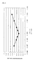
- Fig. 2 is a graph showing the frequency versus the amplitude balancing degree obtained in the configuration of the first embodiment.
- Fig. 3 is a graph showing the phase balancing degree.
- the frequency of the pass band in the DCS reception filter ranges from 1805 MHz to 1880 MHz.
- the maximum phase balancing degree in this range is 9° for the comparison example, and is 6.5° for the first embodiment. That is, the phase balancing degree is improved by 2.5°.
- the amplitude balancing degrees for the comparison example and the first embodiment are not different from each other, that is, 0.8 dB.
- the electrode fingers of the IDT 407 adjacent to the respective IDTs 408 and 409 are grounding electrodes, while the electrode fingers in the IDT 412 adjacent to the respective IDTs 413 and 414 are signal electrodes. This is one of the reasons for which the balancing degrees are deteriorated in the configuration of Fig. 1. Thus, if the following correction is not made, the frequency and phase characteristics of the surface acoustic wave filters 420 and 421 are deviated from each other. As a result, the balancing degrees are deteriorated.
- the pitch ratios of the reflectors 415 and 416 and the respective IDTs 413, 412, and 414 are set to be constant, respectively, and moreover, the pitches in the IDTs 413, 412, and 414 are set to be smaller than those in the IDTs 408, 407, and 409, whereby the deviations between the frequency and phase characteristics of the surface acoustic wave filters 420 and 421 are corrected, and the balancing degrees are improved.
- Figs. 4 and 5 shows the results.
- the ratios of the wavelengths caused by the surface acoustic wave element 402 to those by the surface acoustic wave element 401 determined by the pitches of the IDTs thereof are plotted as abscissa.
- the ratios fI1/fI2 in which fI1(fis) is the frequency determined by the pitch in the IDTs of the surface acoustic wave element 401 and the sound velocity, and fl2 (fir) is the frequency determined by the pitch in the IDTs of the surface acoustic wave element 402 and the sound velocity are plotted as abscissa.
- the amplitude balancing degree and the phase balancing degree is similarly changed as shown in Figs. 4 and 5.
- the amplitude balancing degree is improved when the pitch ratios ( ⁇ I2/ ⁇ I2) of the respective IDTs in the surface acoustic wave elements 401 and 402 or the frequency ratios (fI1/fI2) determined by the pitches and the sound velocity are in the range between about 0.9982 and less than 0.9, preferably, in the range between 0.9985 and less than 0.9995, compared with that obtained when the wavelengths are the same (the pitches are the same) or the frequencies are the same.
- the phase balancing degree becomes minimum at nearly 0.999, and is improved in the range between 0.9982 and less than 1, preferably, in the range between 0.9986 and 0.9996, compared to that obtained when the wavelengths are the same (the pitches are the same) or the frequencies are the same.
- the pitches in the IDTs of the surface acoustic wave element 402 in which the electrode fingers of the center IDT adjacent to the IDTs on the right and left sides, respectively, are signal electrodes, and the electrode fingers of the IDTs on the right and left sides of the center IDT and adjacent to the center IDT are grounding electrodes, respectively, are set to be smaller than the pitches in the IDTs of the surface acoustic wave element 401.
- phase and amplitude characteristics of the surface acoustic wave filter 421 are frequency-shifted so as to be ideally inverted with respect to those of the surface acoustic wave filter 420, since the pitch ratios of the IDTs on the right and left sides are changed.
- the pitch ratio of the reflectors and the IDTs of the element is constant, and only the pitches in the IDTs are changed.
- the pitch ratio is not constant, the same advantages can be obtained, provided that the pitch ratio is changed in the range in which the characteristics are not significantly changed.
- the surface acoustic wave device is formed in such a manner that the pitch in the IDTs of each of the surface acoustic wave elements 401 and 402 is constant. Similar advantages can be also obtained, when the pitch in the IDTs is not constant, that is, the pitch of one pair of electrode fingers in the IDTs is different from the pitch of the other electrode fingers in the IDTs, and the frequency ratio of the surface acoustic wave elements 401 and 402 is set so as to satisfy the above-described conditions.
- no reflectors are provided for the one-terminal-pair surface acoustic wave resonators 403 and 404. Similar advantages can be also obtained, when reflectors are formed to provide surface acoustic wave resonators having a high Q value characteristic.
- Figs. 6 to 8 show modifications of the first embodiment.
- the pitches of the IDTs of the first surface acoustic wave element and the second surface acoustic wave element are set to be different from each other, and thereby, the surface acoustic wave device having improved amplitude and phase balancing degrees can be provided.
- the piezoelectric substrate 20 made of 40 ⁇ 5° Y-cut X-propagation LiTaO3 is used.
- the present invention is not restricted onto the piezoelectric substrate 20.
- the same advantages can be also obtained when piezoelectric substrates made of 64 ⁇ 72° Y-cut X-propagation LiNbO3, 41° Y-cut X-propagation LiNbO3 or the like are used.
- the second embodiment is different from the first embodiment as follows.
- the pitch in the surface acoustic wave element 401 is set to be different from that in the surface acoustic wave element 402.
- the pitch of the one-terminal-pair surface acoustic wave resonator 405 is set to be different from that of the one-terminal-pair surface acoustic wave resonator 406.
- Fig. 9 is a graph showing the frequency versus the amplitude balancing degree obtained in the configuration of the second embodiment.
- Fig. 10 is a graph showing the frequency versus the phase balancing degree.
- the frequency of the pass band in a DCS reception filter ranges from 1805 MHz to 1880 MHz.
- the maximum phase balancing degree in this range is 9° for the comparative example and is 7.5° for the second embodiment. That is, the phase balancing degree is improved by 1.5°.
- the amplitude balancing degree is 0.8 dB for the comparative example and is 1.0 dB for the second embodiment. That is, the amplitude balancing degree is deteriorated by 0.2 dB.
- the pitch of the one-terminal-pair surface acoustic wave resonator 406 is changed based on that of the one-terminal-pair surface acoustic wave resonator 405.
- Fig. 11 shows the change of the maximum amplitude balancing degree in the applicable frequency range (pass band) of the DCS reception filter.
- Fig. 12 shows the change of the phase balancing degree.
- the ratio of the wavelength determined by the pitch of the one-terminal-pair surface acoustic wave resonator 406 based on the wavelength determined by the pitch of the one-terminal-pair surface acoustic wave resonator 405 is plotted as abscissa.
- the frequency ratio fto1/fto2 is plotted as abscissa, in which fto1(fts) represents the frequency determined by the pitch of the one-terminal-pair surface acoustic wave resonator 405 and the sound velocity, and fto2(ftr) represents the frequency determined by the pitch of the one-terminal-pair surface acoustic wave resonator 406 and the sound velocity.
- fto1(fts) represents the frequency determined by the pitch of the one-terminal-pair surface acoustic wave resonator 405 and the sound velocity
- fto2(ftr) represents the frequency determined by the pitch of the one-terminal-pair surface acoustic wave resonator 406 and the sound velocity.
- the amplitude balancing degree and the phase balancing degree present changes similar to those shown in Figs. 11 and 12,
- the amplitude balancing degree is improved by setting the pitch of the one-terminal-pair surface acoustic wave resonator 406 to be smaller than that of the one-terminal-pair surface acoustic wave resonator 405.
- the phase balancing degree is improved by setting the pitch of the one-terminal-pair surface acoustic wave resonator 406 to be larger than that of the one-terminal-pair surface acoustic wave resonator 405.
- both of the amplitude balancing degree and the phase balancing degree are not improved in contrast to the case in which the pitches of the surface acoustic wave elements 401 and 402 are set to be different from each other as described above.
- the second embodiment is effective when one of the amplitude balancing degree and the phase balancing degree is desired to be enhanced even if the other is deteriorated to some degree.
- the ratio is 0.994 or larger.
- the same advantages can be also obtained when the pitches in the one-terminal-pair surface acoustic wave resonators 403 and 404 connected to the unbalanced terminal 417 side are set to be different from each other.
- the surface acoustic wave device of the second embodiment uses the two surface acoustic wave elements.
- the one-terminal-pair surface acoustic wave resonators are connected in series with at least one of the input-output sides of the two surface acoustic wave elements, respectively, and the pitches of the one-terminal-pair surface acoustic wave resonators provided on the right and left sides are set to be different from each other.
- the surface acoustic wave device of which at least one of the amplitude balancing degree and the phase balancing degree caused between the balanced terminals is improved can be provided.
- Fig. 13 shows a modification of the second embodiment.
Landscapes
- Physics & Mathematics (AREA)
- Acoustics & Sound (AREA)
- Surface Acoustic Wave Elements And Circuit Networks Thereof (AREA)
Applications Claiming Priority (4)
| Application Number | Priority Date | Filing Date | Title |
|---|---|---|---|
| JP2001260152 | 2001-08-29 | ||
| JP2001260152 | 2001-08-29 | ||
| JP2002053942 | 2002-02-28 | ||
| JP2002053942A JP3826816B2 (ja) | 2001-08-29 | 2002-02-28 | 弾性表面波装置 |
Publications (3)
| Publication Number | Publication Date |
|---|---|
| EP1289135A2 true EP1289135A2 (fr) | 2003-03-05 |
| EP1289135A3 EP1289135A3 (fr) | 2009-12-30 |
| EP1289135B1 EP1289135B1 (fr) | 2012-07-04 |
Family
ID=26621251
Family Applications (1)
| Application Number | Title | Priority Date | Filing Date |
|---|---|---|---|
| EP02019117A Expired - Lifetime EP1289135B1 (fr) | 2001-08-29 | 2002-08-29 | Dispositif à ondes acoustiques de surface |
Country Status (5)
| Country | Link |
|---|---|
| US (1) | US6771145B2 (fr) |
| EP (1) | EP1289135B1 (fr) |
| JP (1) | JP3826816B2 (fr) |
| KR (1) | KR100489778B1 (fr) |
| CN (1) | CN1178383C (fr) |
Cited By (5)
| Publication number | Priority date | Publication date | Assignee | Title |
|---|---|---|---|---|
| EP1330027A2 (fr) | 2002-01-22 | 2003-07-23 | Murata Manufacturing Co., Ltd. | Dispositif à ondes acoustiques de surface et dispositif de communication le contenant |
| GB2388726A (en) * | 2002-05-15 | 2003-11-19 | Murata Manufacturing Co | Surface acoustic wave balanced-unbalanced converter with modified impedance |
| WO2008104542A1 (fr) * | 2007-03-01 | 2008-09-04 | Epcos Ag | Filtre à résonateurs à ondes de surface |
| US8354897B2 (en) | 2009-04-14 | 2013-01-15 | Murata Manufacturing Co., Ltd. | Elastic wave filter and communication device |
| DE102007063858B3 (de) * | 2007-03-01 | 2016-07-21 | Epcos Ag | Mit Oberflächenwellen arbeitendes Resonator-Filter |
Families Citing this family (12)
| Publication number | Priority date | Publication date | Assignee | Title |
|---|---|---|---|---|
| JP3985717B2 (ja) * | 2003-04-10 | 2007-10-03 | 株式会社村田製作所 | 弾性表面波装置およびそれを用いた通信装置 |
| JP4100249B2 (ja) * | 2003-05-19 | 2008-06-11 | 株式会社村田製作所 | 弾性表面波装置、通信機 |
| JP4438799B2 (ja) | 2004-12-24 | 2010-03-24 | 株式会社村田製作所 | バランス型sawフィルタ |
| JP2007104052A (ja) * | 2005-09-30 | 2007-04-19 | Nippon Dempa Kogyo Co Ltd | 弾性表面波フィルタ |
| JPWO2008038502A1 (ja) * | 2006-09-25 | 2010-01-28 | 株式会社村田製作所 | 弾性境界波フィルタ装置 |
| US8476991B2 (en) * | 2007-11-06 | 2013-07-02 | Panasonic Corporation | Elastic wave resonator, elastic wave filter, and antenna sharing device using the same |
| EP2355348B1 (fr) * | 2008-11-25 | 2018-03-07 | Murata Manufacturing Co., Ltd. | Dispositif de filtre d' onde élastique |
| JP5281489B2 (ja) * | 2009-06-09 | 2013-09-04 | 太陽誘電株式会社 | 弾性表面波デバイス |
| US9041486B2 (en) | 2009-06-18 | 2015-05-26 | Skyworks Panasonic Filter Solutions Japan Co., Ltd | Ladder type surface acoustic wave filter and duplexer using same |
| CN102783021B (zh) * | 2010-03-11 | 2014-12-17 | 株式会社村田制作所 | 弹性波装置 |
| JP6465065B2 (ja) * | 2016-04-25 | 2019-02-06 | 株式会社村田製作所 | 弾性波装置 |
| CN109643985B (zh) * | 2016-08-25 | 2022-11-25 | 株式会社村田制作所 | 弹性波装置 |
Citations (8)
| Publication number | Priority date | Publication date | Assignee | Title |
|---|---|---|---|---|
| EP0644605A1 (fr) * | 1993-09-22 | 1995-03-22 | Motorola, Inc. | Circuit et méthode pour la compensation d'un symétriseur |
| EP0845858A2 (fr) * | 1996-11-28 | 1998-06-03 | Fujitsu Limited | Dispositif à ondes acoustiques de surface |
| DE19818038A1 (de) * | 1998-04-22 | 1999-11-04 | Siemens Matsushita Components | Dualmode-Oberflächenwellenfilter |
| EP1126605A2 (fr) * | 2000-02-14 | 2001-08-22 | Murata Manufacturing Co., Ltd. | Dispositif de filtrage à ondes acoustiques de surface |
| EP1158672A2 (fr) * | 2000-05-22 | 2001-11-28 | Murata Manufacturing Co., Ltd. | Filtre à ondes acoustiques de surface du type à résonateur couplé transversalement |
| EP1330027A2 (fr) * | 2002-01-22 | 2003-07-23 | Murata Manufacturing Co., Ltd. | Dispositif à ondes acoustiques de surface et dispositif de communication le contenant |
| EP1337039A1 (fr) * | 2002-02-15 | 2003-08-20 | Murata Manufacturing Co., Ltd. | Dispositif à ondes acoustiques de surface et dispositif de communication |
| EP1341304A2 (fr) * | 2002-02-28 | 2003-09-03 | Murata Manufacturing Co., Ltd. | Filtre à ondes acoustiques de surface |
Family Cites Families (7)
| Publication number | Priority date | Publication date | Assignee | Title |
|---|---|---|---|---|
| JP3293671B2 (ja) | 1992-12-01 | 2002-06-17 | 日本無線株式会社 | 弾性表面波フィルタ |
| JPH09130203A (ja) * | 1995-11-01 | 1997-05-16 | Toyo Commun Equip Co Ltd | 二段縦続接続縦結合二重モードsawフィルタ |
| JP3113199B2 (ja) * | 1996-01-30 | 2000-11-27 | 株式会社東芝 | 弾性表面波装置 |
| JP3239064B2 (ja) * | 1996-05-28 | 2001-12-17 | 富士通株式会社 | 弾性表面波装置 |
| JP3204112B2 (ja) * | 1996-08-28 | 2001-09-04 | 株式会社村田製作所 | 弾性表面波共振子フィルタ |
| JP2001230659A (ja) * | 1999-12-09 | 2001-08-24 | Sanyo Electric Co Ltd | 弾性表面波素子 |
| JP3687566B2 (ja) * | 2000-07-25 | 2005-08-24 | 株式会社村田製作所 | 縦結合共振子型弾性表面波フィルタ |
-
2002
- 2002-02-28 JP JP2002053942A patent/JP3826816B2/ja not_active Expired - Lifetime
- 2002-08-28 KR KR10-2002-0051109A patent/KR100489778B1/ko active IP Right Grant
- 2002-08-29 US US10/230,038 patent/US6771145B2/en not_active Expired - Lifetime
- 2002-08-29 CN CNB021319898A patent/CN1178383C/zh not_active Expired - Lifetime
- 2002-08-29 EP EP02019117A patent/EP1289135B1/fr not_active Expired - Lifetime
Patent Citations (8)
| Publication number | Priority date | Publication date | Assignee | Title |
|---|---|---|---|---|
| EP0644605A1 (fr) * | 1993-09-22 | 1995-03-22 | Motorola, Inc. | Circuit et méthode pour la compensation d'un symétriseur |
| EP0845858A2 (fr) * | 1996-11-28 | 1998-06-03 | Fujitsu Limited | Dispositif à ondes acoustiques de surface |
| DE19818038A1 (de) * | 1998-04-22 | 1999-11-04 | Siemens Matsushita Components | Dualmode-Oberflächenwellenfilter |
| EP1126605A2 (fr) * | 2000-02-14 | 2001-08-22 | Murata Manufacturing Co., Ltd. | Dispositif de filtrage à ondes acoustiques de surface |
| EP1158672A2 (fr) * | 2000-05-22 | 2001-11-28 | Murata Manufacturing Co., Ltd. | Filtre à ondes acoustiques de surface du type à résonateur couplé transversalement |
| EP1330027A2 (fr) * | 2002-01-22 | 2003-07-23 | Murata Manufacturing Co., Ltd. | Dispositif à ondes acoustiques de surface et dispositif de communication le contenant |
| EP1337039A1 (fr) * | 2002-02-15 | 2003-08-20 | Murata Manufacturing Co., Ltd. | Dispositif à ondes acoustiques de surface et dispositif de communication |
| EP1341304A2 (fr) * | 2002-02-28 | 2003-09-03 | Murata Manufacturing Co., Ltd. | Filtre à ondes acoustiques de surface |
Non-Patent Citations (1)
| Title |
|---|
| V. PLESSKY AND J. KOSKELA: "Coupling-of-modes analysis of SAW devices" INTERNATIONAL JOURNAL OF HIGH SPEED ELECTRONICS AND SYSTEMS, vol. 10, no. 4, 31 December 2000 (2000-12-31), pages 867-947, XP002491166 * |
Cited By (10)
| Publication number | Priority date | Publication date | Assignee | Title |
|---|---|---|---|---|
| EP1330027A2 (fr) | 2002-01-22 | 2003-07-23 | Murata Manufacturing Co., Ltd. | Dispositif à ondes acoustiques de surface et dispositif de communication le contenant |
| EP1330027A3 (fr) * | 2002-01-22 | 2009-01-14 | Murata Manufacturing Co., Ltd. | Dispositif à ondes acoustiques de surface et dispositif de communication le contenant |
| GB2388726A (en) * | 2002-05-15 | 2003-11-19 | Murata Manufacturing Co | Surface acoustic wave balanced-unbalanced converter with modified impedance |
| GB2388726B (en) * | 2002-05-15 | 2004-07-07 | Murata Manufacturing Co | Surface acoustic wave device and communication device containing the same |
| US6876275B2 (en) | 2002-05-15 | 2005-04-05 | Murata Manufacturing Co., Ltd. | Surface acoustic wave device and communication device containing the same |
| WO2008104542A1 (fr) * | 2007-03-01 | 2008-09-04 | Epcos Ag | Filtre à résonateurs à ondes de surface |
| US8026780B2 (en) | 2007-03-01 | 2011-09-27 | Epcos Ag | Resonator filter working with surface acoustic waves |
| DE102007010040B4 (de) * | 2007-03-01 | 2014-08-07 | Epcos Ag | Mit Oberflächenwellen arbeitendes DMS-Filter |
| DE102007063858B3 (de) * | 2007-03-01 | 2016-07-21 | Epcos Ag | Mit Oberflächenwellen arbeitendes Resonator-Filter |
| US8354897B2 (en) | 2009-04-14 | 2013-01-15 | Murata Manufacturing Co., Ltd. | Elastic wave filter and communication device |
Also Published As
| Publication number | Publication date |
|---|---|
| CN1404220A (zh) | 2003-03-19 |
| CN1178383C (zh) | 2004-12-01 |
| US20030062970A1 (en) | 2003-04-03 |
| KR20030019172A (ko) | 2003-03-06 |
| EP1289135A3 (fr) | 2009-12-30 |
| EP1289135B1 (fr) | 2012-07-04 |
| KR100489778B1 (ko) | 2005-05-16 |
| US6771145B2 (en) | 2004-08-03 |
| JP2003152502A (ja) | 2003-05-23 |
| JP3826816B2 (ja) | 2006-09-27 |
Similar Documents
| Publication | Publication Date | Title |
|---|---|---|
| US6815868B2 (en) | Surface acoustic wave apparatus and communication unit | |
| EP1126605B1 (fr) | Dispositif de filtrage à ondes acoustiques de surface | |
| US7034639B2 (en) | Longitudinally coupled resonator type surface acoustic wave filter and communication apparatus incorporating the same | |
| US7902940B2 (en) | Duplexer | |
| EP1289135B1 (fr) | Dispositif à ondes acoustiques de surface | |
| US7378923B2 (en) | Balanced SAW filter | |
| JP3685102B2 (ja) | 弾性表面波フィルタ、通信装置 | |
| US6753641B2 (en) | Surface acoustic wave device and communication device | |
| KR100493215B1 (ko) | 탄성 표면파 필터 | |
| JP4412326B2 (ja) | バランス型sawフィルタ | |
| EP2254244B1 (fr) | Filtre symétriseur et duplexeur | |
| US7042313B2 (en) | Surface acoustic wave device and communication device using the same | |
| US20030035557A1 (en) | Surface acoustic wave device | |
| US6720847B2 (en) | Longitudinally-coupled resonator surface acoustic wave filter and communication apparatus using the same | |
| US7369016B2 (en) | Balanced saw filter | |
| JP3820954B2 (ja) | 弾性表面波装置、通信装置 | |
| JP3478280B2 (ja) | 弾性表面波フィルタ、通信装置 | |
| JP2003179458A (ja) | 弾性表面波装置、通信装置 | |
| JP3454260B2 (ja) | 弾性表面波フィルタ、通信装置 | |
| JP2004112591A (ja) | 弾性表面波フィルタ、通信装置 |
Legal Events
| Date | Code | Title | Description |
|---|---|---|---|
| PUAI | Public reference made under article 153(3) epc to a published international application that has entered the european phase |
Free format text: ORIGINAL CODE: 0009012 |
|
| 17P | Request for examination filed |
Effective date: 20020829 |
|
| AK | Designated contracting states |
Designated state(s): AT BE BG CH CY CZ DE DK EE ES FI FR GB GR IE IT LI LU MC NL PT SE SK TR Kind code of ref document: A2 Designated state(s): AT BE BG CH CY CZ DE DK EE ES FI FR GB GR IE IT LI LU MC NL PT SE SK TR |
|
| AX | Request for extension of the european patent |
Extension state: AL LT LV MK RO SI |
|
| RAP1 | Party data changed (applicant data changed or rights of an application transferred) |
Owner name: MURATA MANUFACTURING CO., LTD. |
|
| RIC1 | Information provided on ipc code assigned before grant |
Ipc: H03H 9/64 20060101AFI20021220BHEP Ipc: H03H 9/00 20060101ALI20081128BHEP |
|
| PUAL | Search report despatched |
Free format text: ORIGINAL CODE: 0009013 |
|
| AK | Designated contracting states |
Kind code of ref document: A3 Designated state(s): AT BE BG CH CY CZ DE DK EE ES FI FR GB GR IE IT LI LU MC NL PT SE SK TR |
|
| AX | Request for extension of the european patent |
Extension state: AL LT LV MK RO SI |
|
| AKX | Designation fees paid |
Designated state(s): DE FR GB |
|
| 17Q | First examination report despatched |
Effective date: 20110228 |
|
| REG | Reference to a national code |
Ref country code: DE Ref legal event code: R079 Ref document number: 60243252 Country of ref document: DE Free format text: PREVIOUS MAIN CLASS: H03H0009640000 Ipc: H03H0009145000 |
|
| GRAP | Despatch of communication of intention to grant a patent |
Free format text: ORIGINAL CODE: EPIDOSNIGR1 |
|
| RIC1 | Information provided on ipc code assigned before grant |
Ipc: H03H 9/64 20060101ALI20111219BHEP Ipc: H03H 9/145 20060101AFI20111219BHEP Ipc: H03H 9/00 20060101ALI20111219BHEP |
|
| GRAS | Grant fee paid |
Free format text: ORIGINAL CODE: EPIDOSNIGR3 |
|
| GRAA | (expected) grant |
Free format text: ORIGINAL CODE: 0009210 |
|
| AK | Designated contracting states |
Kind code of ref document: B1 Designated state(s): DE FR GB |
|
| REG | Reference to a national code |
Ref country code: GB Ref legal event code: FG4D |
|
| REG | Reference to a national code |
Ref country code: DE Ref legal event code: R096 Ref document number: 60243252 Country of ref document: DE Effective date: 20120823 |
|
| PLBE | No opposition filed within time limit |
Free format text: ORIGINAL CODE: 0009261 |
|
| STAA | Information on the status of an ep patent application or granted ep patent |
Free format text: STATUS: NO OPPOSITION FILED WITHIN TIME LIMIT |
|
| REG | Reference to a national code |
Ref country code: FR Ref legal event code: ST Effective date: 20130430 |
|
| 26N | No opposition filed |
Effective date: 20130405 |
|
| GBPC | Gb: european patent ceased through non-payment of renewal fee |
Effective date: 20121004 |
|
| PG25 | Lapsed in a contracting state [announced via postgrant information from national office to epo] |
Ref country code: GB Free format text: LAPSE BECAUSE OF NON-PAYMENT OF DUE FEES Effective date: 20121004 |
|
| REG | Reference to a national code |
Ref country code: DE Ref legal event code: R097 Ref document number: 60243252 Country of ref document: DE Effective date: 20130405 |
|
| PG25 | Lapsed in a contracting state [announced via postgrant information from national office to epo] |
Ref country code: FR Free format text: LAPSE BECAUSE OF NON-PAYMENT OF DUE FEES Effective date: 20120904 |
|
| PGFP | Annual fee paid to national office [announced via postgrant information from national office to epo] |
Ref country code: DE Payment date: 20210819 Year of fee payment: 20 |
|
| REG | Reference to a national code |
Ref country code: DE Ref legal event code: R071 Ref document number: 60243252 Country of ref document: DE |