EP1285755A1 - Beschichtungsmaschine zum Veredeln von Druckbogen - Google Patents
Beschichtungsmaschine zum Veredeln von Druckbogen Download PDFInfo
- Publication number
- EP1285755A1 EP1285755A1 EP02017512A EP02017512A EP1285755A1 EP 1285755 A1 EP1285755 A1 EP 1285755A1 EP 02017512 A EP02017512 A EP 02017512A EP 02017512 A EP02017512 A EP 02017512A EP 1285755 A1 EP1285755 A1 EP 1285755A1
- Authority
- EP
- European Patent Office
- Prior art keywords
- sheet
- coating unit
- unit
- dryer
- coating
- Prior art date
- Legal status (The legal status is an assumption and is not a legal conclusion. Google has not performed a legal analysis and makes no representation as to the accuracy of the status listed.)
- Granted
Links
- 238000000576 coating method Methods 0.000 title claims abstract description 146
- 239000011248 coating agent Substances 0.000 title claims abstract description 141
- 238000001035 drying Methods 0.000 claims abstract description 18
- 238000007639 printing Methods 0.000 claims description 28
- 238000009499 grossing Methods 0.000 claims description 19
- 239000000463 material Substances 0.000 claims description 10
- 238000012546 transfer Methods 0.000 claims description 10
- 239000002826 coolant Substances 0.000 claims description 9
- 230000009969 flowable effect Effects 0.000 claims description 8
- 238000004080 punching Methods 0.000 claims description 7
- 238000004049 embossing Methods 0.000 claims description 5
- 238000005520 cutting process Methods 0.000 claims description 2
- 239000002966 varnish Substances 0.000 description 7
- 238000011161 development Methods 0.000 description 6
- 238000012549 training Methods 0.000 description 6
- 239000010410 layer Substances 0.000 description 5
- 238000010422 painting Methods 0.000 description 5
- 238000012545 processing Methods 0.000 description 4
- 239000006185 dispersion Substances 0.000 description 3
- 230000000694 effects Effects 0.000 description 3
- 238000000034 method Methods 0.000 description 3
- 239000000126 substance Substances 0.000 description 3
- XEEYBQQBJWHFJM-UHFFFAOYSA-N Iron Chemical compound [Fe] XEEYBQQBJWHFJM-UHFFFAOYSA-N 0.000 description 2
- PXHVJJICTQNCMI-UHFFFAOYSA-N Nickel Chemical compound [Ni] PXHVJJICTQNCMI-UHFFFAOYSA-N 0.000 description 2
- 238000010276 construction Methods 0.000 description 2
- 238000005259 measurement Methods 0.000 description 2
- 239000003973 paint Substances 0.000 description 2
- 239000000843 powder Substances 0.000 description 2
- 238000011144 upstream manufacturing Methods 0.000 description 2
- VYZAMTAEIAYCRO-UHFFFAOYSA-N Chromium Chemical compound [Cr] VYZAMTAEIAYCRO-UHFFFAOYSA-N 0.000 description 1
- ZOKXTWBITQBERF-UHFFFAOYSA-N Molybdenum Chemical compound [Mo] ZOKXTWBITQBERF-UHFFFAOYSA-N 0.000 description 1
- 238000005299 abrasion Methods 0.000 description 1
- 239000000956 alloy Substances 0.000 description 1
- 229910045601 alloy Inorganic materials 0.000 description 1
- 239000010941 cobalt Substances 0.000 description 1
- 229910017052 cobalt Inorganic materials 0.000 description 1
- GUTLYIVDDKVIGB-UHFFFAOYSA-N cobalt atom Chemical compound [Co] GUTLYIVDDKVIGB-UHFFFAOYSA-N 0.000 description 1
- 238000001816 cooling Methods 0.000 description 1
- 238000004132 cross linking Methods 0.000 description 1
- 238000013461 design Methods 0.000 description 1
- 238000007598 dipping method Methods 0.000 description 1
- 229910052742 iron Inorganic materials 0.000 description 1
- 238000002372 labelling Methods 0.000 description 1
- 239000004922 lacquer Substances 0.000 description 1
- 239000007788 liquid Substances 0.000 description 1
- 238000005461 lubrication Methods 0.000 description 1
- 238000004519 manufacturing process Methods 0.000 description 1
- 229910052751 metal Inorganic materials 0.000 description 1
- 239000002184 metal Substances 0.000 description 1
- 150000002739 metals Chemical class 0.000 description 1
- 239000000203 mixture Substances 0.000 description 1
- 229910052750 molybdenum Inorganic materials 0.000 description 1
- 239000011733 molybdenum Substances 0.000 description 1
- 229910052759 nickel Inorganic materials 0.000 description 1
- 238000007645 offset printing Methods 0.000 description 1
- 230000001590 oxidative effect Effects 0.000 description 1
- 238000004064 recycling Methods 0.000 description 1
- 238000007789 sealing Methods 0.000 description 1
- 239000002356 single layer Substances 0.000 description 1
- 238000003860 storage Methods 0.000 description 1
- WFKWXMTUELFFGS-UHFFFAOYSA-N tungsten Chemical compound [W] WFKWXMTUELFFGS-UHFFFAOYSA-N 0.000 description 1
- 229910052721 tungsten Inorganic materials 0.000 description 1
- 239000010937 tungsten Substances 0.000 description 1
Images

Classifications
-
- B—PERFORMING OPERATIONS; TRANSPORTING
- B41—PRINTING; LINING MACHINES; TYPEWRITERS; STAMPS
- B41F—PRINTING MACHINES OR PRESSES
- B41F25/00—Devices for pressing sheets or webs against cylinders, e.g. for smoothing purposes
-
- B—PERFORMING OPERATIONS; TRANSPORTING
- B41—PRINTING; LINING MACHINES; TYPEWRITERS; STAMPS
- B41F—PRINTING MACHINES OR PRESSES
- B41F23/00—Devices for treating the surfaces of sheets, webs, or other articles in connection with printing
- B41F23/04—Devices for treating the surfaces of sheets, webs, or other articles in connection with printing by heat drying, by cooling, by applying powders
- B41F23/044—Drying sheets, e.g. between two printing stations
-
- B—PERFORMING OPERATIONS; TRANSPORTING
- B41—PRINTING; LINING MACHINES; TYPEWRITERS; STAMPS
- B41F—PRINTING MACHINES OR PRESSES
- B41F23/00—Devices for treating the surfaces of sheets, webs, or other articles in connection with printing
- B41F23/08—Print finishing devices, e.g. for glossing prints
Definitions
- the invention relates to a coating machine for finishing of printed sheets using a flowable material the preambles of claims 1, 2 and 3.
- a coating machine of this type is known from DE 298 18 148 U1 and is designed with coating units which are constructed in a row and which are preceded by a feeder unit in the conveying direction of the sheet material.
- the feeder unit In the conveying direction, the feeder unit is followed by at least one first coating unit for the sheet front, which is followed by a switchable sheet turning unit.
- the sheet turning unit is followed in the conveying direction by at least one first coating unit for the sheet back, which in turn is followed by a delivery unit.
- Sheet transport can only be carried out using sheet guide cylinders.
- dryer modules are arranged between the coating units, each of which is specifically formed from a transfer drum and a downstream impression cylinder with an assigned dryer system. In terms of process-stable drying, these dryer modules are disadvantageous for certain finishing orders.
- the invention has for its object a coating machine of the kind described in the introduction to create the especially the coating quality of the printed sheets one-sided or double-sided coating increased.
- the task is based on the training features of claims 1, 2 or 3 solved. Further training results itself from the subclaims.
- a first advantage of the coating machine is that that in inline operation a one-sided (front) or a double-sided (front and back) coating of printing sheets in high coating quality in connection with process-stable drying.
- the one-sided and two-sided coating is also as Multiple coating possible.
- the press sheets are before Running into the subsequent coating unit or subsequent sheet turning unit better, especially more even, dried, which is particularly due to the training of Dryer devices is required. Through the process stable Drying is a risk of marks, scratches or Lubrication effects on the printed sheet noticeably reduced and one Increase in production output and higher shift orders are feasible.
- Another advantage is that previously in a processing machine, e.g. an offset printing machine and / or one Rotogravure machine, printed sheets then produced in the created coating machine are refinable or unprinted printed sheets, e.g. Recycling material, right in the Coating machine can be refined.
- a processing machine e.g. an offset printing machine and / or one Rotogravure machine
- Another advantage is that especially with both sides printed sheets the coatings individually on the front or back of the printed sheets - at one Process stable drying - can be applied to the coating quality to increase.
- a printed Front in particular a single-layer coating can be applied and in particular a two-layer for the back Coating can be applied (and vice versa).
- At least the first coating unit for the front is arranged downstream of a dryer device is preferably variable in length.
- a dryer device serves to improve the coating quality the printing sheet through process-stable drying.
- the coated printed sheet remains - depending on what is used flowable material - enough time to knock it off oxidative drying or for crosslinking.
- more flowable Aqueous dispersion varnishes UV varnishes, Flexo paint, opaque white or pigmented paints can be used.
- the printed sheets are therefore noticeably better dried before this in the conveying direction, for example to the next coating device, alternatively a smoothing device or another processing device for the sheet front, be handed over.
- this next Coating / smoothing device in the conveying direction of a sheet turning unit follows and that this at least one coating unit for the back of the sheet follows.
- the latter preferably follows Coating unit a dryer device with dryer systems, which is preferably variable in length, a further coating device or Processing device, or directly a boom unit with dryer systems.
- the forme cylinders universally usable by choosing the forme cylinder a printing / varnish plate (e.g. Planographic printing form, flexible printing form), a punching device, preferably a punching plate, a perforating plate or a perforating knife, an embossing plate, a smoothing plate or carries a grooved plate.
- a printing / varnish plate e.g. Planographic printing form, flexible printing form
- a punching device preferably a punching plate, a perforating plate or a perforating knife, an embossing plate, a smoothing plate or carries a grooved plate.
- the sheet turning unit the coating machine in its operating mode is switchable. So the coating machine is with their coating units for one-sided (straight printing) as well as double-sided coating (perfecting and reverse printing) the printed sheet can be used.
- each coating unit has a forme cylinder with plate clamping means and a plate changing device on. So that is on the coating machine Coating units with a shorter set-up time enabling construction feasible.
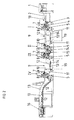
- a coating machine points in the conveying direction 18 the printed sheet on a feeder unit, which by a feeder 1 and a feed table 2, preferably one Suction belt table, is formed.
- the feed table 2 is followed by one first coating unit I for the sheet front, the et al a vibrating device 3, a system drum 4, a Forme cylinder 6 and as a sheet guide cylinder a printing cylinder 5 has.
- the form cylinder 6 is a metering system for a flowable substance, for example a dispersion or UV varnish, a screened applicator roller 7 with a doctor blade 8 assigned.
- the first coating unit I for the sheet front a first dryer device 9 follows in the conveying direction 18.
- This dryer device 9 has an endlessly rotating one Funding means 10 with two deflection elements 11 and horizontally arranged runs and at intervals arranged thereon Sheet holding systems 13.
- Parallel to the lower run of the Funding means 10 is at least one dryer system 12, for example IR dryer, thermal air dryer or UV dryer, arranged above the sheet conveying plane.
- IR dryer thermal air dryer or UV dryer
- a sheet guide device 14 for example pneumatically loaded, arranged.
- the dryer device 9 is any number of Dryer systems 12 in the conveying direction 18 one after the other can be arranged horizontally.
- a sheet guiding device 14 which can be acted upon pneumatically, its guiding surface is in functional connection in particular with a coolant system.
- a coolant system is preferably formed by coolant channels arranged on a surface opposite the guide surface for the sheet guide.
- a coolant which is preferably processed in a cooling circuit, can flow through the coolant channels.
- Such a design is known for example from DE 298 16 734 U1.
- the dryer device 9 is followed in the conveying direction 18 second coating unit II for the sheet front, which, analogous to the first coating unit I, a forme cylinder 6, a rastered application roller 7 with a doctor blade 8 and has a pressure cylinder 5.
- This second coating unit II for the sheet front follows in Conveying direction 18 a sheet turning unit 15.
- the forme cylinder 6 in the conveying direction 18 second coating unit II for the sheet front Dryer system 12 at a distance from the sheet-guiding printing cylinder 5 subordinate.
- a dryer system 12 is for example a UV dryer.
- the second coating unit is alternatively II only with a sheet-guiding pressure cylinder 5 and a forme cylinder 6 acting as a smoothing cylinder operated.
- An alternative to the forme cylinder 6 is at least a smoothing roller can be installed.
- the smoothing cylinder is used for Improvement of the mechanical structure of the surface the printed sheet and to increase the gloss. simultaneously the smoothing cylinder supports the sheet guidance a non-active second coating unit II
- forme cylinder 6 carries a smoothing plate or is itself formed as a smoothing cylinder or by a smoothing cylinder interchangeable.
- the smoothing plate or the smoothing cylinder preferably has one non-stick coating consisting of metals such as chrome, Iron, nickel, cobalt or tungsten, their mixtures or Alloys, on. Another preferred coating is Molybdenum. These coatings also have a sealing layer on, which preferably from the group of Polyorganosiloxanes is formed.
- the metering systems for example chamber doctor blade 8 and applicator roller 7, are from the forme cylinder 6 or smoothing cylinder switched off. Alternatively, the dosing systems are also from the Coating unit II removable.
- the coating unit II is preferably for the use of a smoothing device suitable, but their use also in downstream coating units (III - V) realizable.
- the first deflection element 11 in the conveying direction 18 is preferred in the side walls of a frame 19 of the dryer device 9 stored and the second downstream in the conveying direction 18 Deflection element 11 is in the frame of the second coating unit II stored for the front of the sheet.
- the length of the Side walls of the frame 19 (including funding 10, Bow holding systems 13) is individual to the required Dryer section (multiple arrangement of dryer systems 12) customizable.
- the side walls of the frame 19 are in one piece or can be assembled modularly.
- the deflection elements 11 preferably have the same outer diameter on. Furthermore, the axis centers of the Deflection elements 11 are preferably arranged in one plane. As well are the deflecting elements 11 - based on a simple size Forme cylinder 6 - as well as the sheet-guiding cylinders, impression cylinders 5 and possibly transfer cylinder 17 or turning drum of Sheet turning unit 15, with the same diameter, double size educated.
- the sheet turning unit 15 is a first coating unit III for the back of the sheet and this coating unit III is a cantilever unit 16 subordinate.
- the delivery unit 16 has dryer systems 12, for example IR dryer, thermal air dryer, UV dryer, on and circulating funding 10 with sheet holding systems 13 for placing the printed sheets on a delivery stack.
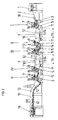
- FIG. 2 in a further development from FIG. 1, the same Machine configuration up to the sheet turning unit 15 - again the first coating unit III for the back of the sheet downstream.
- This is followed by a second dryer device 9, which are identical in construction to that already described, the first coating unit I for the sheet front downstream dryer device 9 (Fig. 1).
- the length the side walls of the frame 19 (including funding 10, sheet holding systems 13) is also individual to the required dryer section (multiple arrangement of Dryer systems 12) customizable.
- the second dryer device 9 thus has endless revolutions Funding means 10, two deflection elements 11 and horizontally arranged runs as well as spaced bow support systems 13, at least one of the lower runs of the Funding 10 assigned above the sheet conveying plane in parallel Dryer system 12 and at least one in the area of Dryer systems 12 parallel below the sheet conveying plane arranged sheet guiding device 14.
- the sheet guide In preferred training, 14 is pneumatic acted upon and the guide surface is preferably with a Coolant system in functional connection.
- the second dryer device 9 is a second coating unit IV for the back of the sheet. It the boom unit 16 closes with dryer systems 12 and sheet guiding devices, which preferably with a Coolant system are in functional connection.
- Figure 3 shows a development of Fig. 2, according to which second coating unit IV for the back of the sheet third coating unit V for the back of the sheet with preferably an intermediate transfer cylinder 17 is subordinate.
- the transfer cylinder is preferably one Sheet guiding device assigned. Instead of the transfer cylinder 17, a dryer device 9 can also be arranged.
- the second coating unit IV for the back of the sheet or the third coating unit V for the back of the sheet optionally have a device for perforating or punching or cutting or numbering or embossing or labeling, for example with security features or coding, the printed sheet on.
- the second coating unit IV is for the Back of sheet can be used for perforating and the third Coating unit V for the back of the sheet is for coating, preferably painting, can be used.
- the printed sheets in third coating unit V for the back of the sheet again coated, preferably painted.
- the Delivery unit 16 with dryer systems 12 and sheet guiding devices, preferably with a coolant system.
- the dosing systems of the coating units I - V are not limited to a doctor blade 8 with applicator roller 7. Much more are two-roll mills with a roll gap from above feedable liquid substance (squeeze roller principle) or Two- and three-roll mills based on the dipping / scoop-roller principle used.
- At least one printing cylinder 5 of a coating device IV and / or of a dryer device 9 is assigned a device for checking the layer thickness or for measuring the gloss.
- a device is preferably arranged at a distance from the sheet-guiding printing cylinder after the contact gap between the forme cylinder 6 and printing cylinder 5 in the conveying direction 18.
- At least one dryer system 12 can additionally be arranged between this contact gap and this device.
- a device for layer thickness measurement or gloss measurement can also be arranged in the dryer device 9 in the conveying direction 18 after the dryer systems 12 at a distance from the conveyed printed sheet.
- the above-described training of the coating machine are not exhausted. Rather, for example in the conveying direction 18 additionally before the first coating unit I another coating unit with at least one sheet-guiding pressure cylinder 5 and one Forme cylinder 6 or a smoothing cylinder or at least one Smoothing roller can be arranged. Such an arrangement is for example advantageous for already printed, with powder pollinated printed sheets. With this upstream coating unit the powder material is smoothable and with the subsequent coatings are the gloss effect and / or the surface smoothness can be improved.
- each coating unit IV has 6 plate clamping means on each forme cylinder.
- the plate clamping means serve to hold the lacquer plate (rubber blanket with a preferably metallic carrier layer, flexible high-pressure mold), the smoothing plate, the perforating, embossing or punching plate and are preferably arranged on the circumferential side of the forme cylinder 6.
- a plate changing device is also assigned to each forme cylinder 6. Such a plate changing device is preferably assigned to each forme cylinder 6 on the side facing the delivery unit 16. Independently of the plate clamping means and the plate changing devices, each forme cylinder 6 is connected to a register setting device.
- the mode of operation is as follows, for example.
- the printed sheets are fed in the conveying direction 18 by means of feeder 1, feed table 2, vibrating device 3, contact drum 4 to the sheet-guiding printing cylinder 5 of the first coating unit I (for the sheet front side).
- the contact gap formed by the forme cylinder 6 (with a rubber blanket; flexible high-pressure mold) and the sheet-guiding printing cylinder 5, painting (full-surface painting; recessed painting) takes place on the front of the printing sheet.
- An aqueous dispersion varnish is used as the flowable substance.
- the printed sheets are then transferred from the printing cylinder 5 to the sheet holding systems 13 of the dryer device 9, guided past the dryer systems 12 in the sheet conveying plane by means of conveying means 10 and transferred to the subsequent printing cylinder 5.
- the forme cylinder 6 is active as a smoothing cylinder and to support the sheet guidance.
- the sheet turning unit 15 the printed sheets are turned according to the principle of trailing edge turning.
- the sheet turning unit 15 can be switched over, so that the function of a transfer cylinder for one-sided coating can also be realized.
- the sheet turning unit 15 is preferably designed as a single-drum or multi-drum with at least one storage drum arranged upstream of the turning drum.
- the sheet turning unit 15 is followed by the first coating unit III (for the back of the sheet).
- the printed sheets are in the first coating unit III (for the back of the sheet), for example with a UV varnish, coated.
- the forme cylinder 6 is a Subordinate UV dryer system 12.
- the printed sheets will be then from the impression cylinder 5 to the sheet holding systems 13 transferred to the dryer device 9 by means of conveying means 10 past the dryer systems 12 in the sheet conveying plane guided and to the subsequent printing cylinder 5 of the second Transfer coating unit IV, coated and then passed to the boom unit 16 and dried.
- the printed sheets in the first coating unit III (for the back of the sheet) with coated with a varnish.
- the printed sheets are then from the printing cylinder 5 to the sheet holding systems 13 of the dryer device 9 passed by means of funding 10 in the Sheet conveying level led past the dryer systems 12 and to the subsequent printing cylinder 5, which is preferred is provided with a counter punching plate, the second coating unit IV passed.
- the forme cylinder 6 carries Perforating / punching sheet and the printing sheets are perforated or punched.
- the printed sheets are sent to the Transfer cylinder 17 and from there to the printing cylinder 5 of the third coating unit V (for the back of the sheet) to hand over.
- the printed sheets are coated again and then transferred to the delivery unit 16 by means of dryer systems 12 dried and placed on the stack.
Landscapes
- Engineering & Computer Science (AREA)
- Mechanical Engineering (AREA)
- Coating Apparatus (AREA)
- Supply, Installation And Extraction Of Printed Sheets Or Plates (AREA)
- Soil Working Implements (AREA)
- Printing Methods (AREA)
Abstract
Description
Unter dem Aspekt der prozeßstabilen Trocknung sind für bestimmte Veredelungsaufträge diese Trocknermodule nachteilig.
- der unterschiedlichen Saugfähigkeit des Materials der Druckbogen, und/oder
- von in oder auf den Druckbogen angeordneten Sujets und/oder Sicherheitsmerkmalen, und/oder
- von Glanzeffekten, und/oder
- des Oberflächenschutzes (Scheuerfestigkeit).
- Fig. 1
- eine Beschichtungsmaschine mit je einer Beschichtungseinheit für die Vorder- und Rückseite von Druckbogen und einer Trocknervorrichtung,
- Fig. 2
- eine Weiterbildung der Beschichtungsmaschine gemäß Fig. 1 mit zwei Trocknervorrichtungen,
- Fig.3
- eine Weiterbildung der Beschichtungsmaschine gemäß Fig. 2 mit einer zusätzlichen Beschichtungseinheit.
Eine derartige Ausbildung ist beispielsweise aus DE 298 16 734 U1 bekannt.
Bevorzugt ist weiterhin in der Trocknervorrichtung 9 in Förderrichtung 18 nach den Trocknersystemen 12 in Abstand zum geförderten Druckbogen eine derartige Einrichtung zur Schichtdickenmessung bzw. Glanzmessung anordenbar.
Unabhängig von den Plattenspannmitteln und den Plattenwechseleinrichtungen ist jeder Formzylinder 6 mit einer Registereinstellvorrichtung verbunden.
Im Kontaktspalt, gebildet von Formzylinder 6 (mit Gummituch; flexibler Hochdruckform) und dem bogenführenden Druckzylinder 5, erfolgt eine Lackierung (vollflächiges Lackieren; ausgespartes Lackieren) auf die Vorderseite der Druckbogen. Als fließfähiger Stoff ist ein wässriger Dispersionslack im Einsatz.
Die Druckbogen werden anschließend vom Druckzylinder 5 an die Bogenhaltesysteme 13 der Trocknervorrichtung 9 übergeben, mittels Fördermittel 10 in der Bogenförderebene an den Trocknersystemen 12 vorbei geführt und an den nachfolgenden Druckzylinder 5 übergeben.
Im Kontaktspalt der nachfolgenden zweiten Beschichtungseinheit II (für die Bogenvorderseite) ist beispielsweise der Formzylinder 6 als Glättzylinder und zur Unterstützung der Bogenführung aktiv.
In der Bogenwendeeinheit 15 werden die Druckbogen nach dem Prinzip der Hinterkantenwendung gewendet. Die Bogenwendeeinheit 15 ist umschaltbar, so dass auch die Funktion eines Transferzylinders für bei einseitiger Beschichtung realisierbar ist. Die Bogenwendeeinheit 15 ist bevorzugt als eine Eintrommelwendung oder eine Mehrtrommelwendung mit wenigstens einer der Wendetrommel vorgeordneten Speichertrommel ausgebildet.
Der Bogenwendeeinheit 15 folgt die erste Beschichtungseinheit III (für die Bogenrückseite). In deren Kontaktspalt, gebildet von Formzylinder 6 (mit flexibler Hochdruckform) und dem bogenführenden Druckzylinder 5, erfolgt eine Spotlackierung (ausgespartes Lackieren) auf die Rückseite der Druckbogen. Danach werden die Druckbogen gemäß Fig. 1 an die Bogenhaltesysteme der Auslegereinheit 16 übergeben und getrocknet.
- 1
- Anleger
- 2
- Zuführtisch
- 3
- Schwingvorrichtung
- 4
- Anlagetrommel
- 5
- Druckzylinder
- 6
- Formzylinder
- 7
- Auftragwalze
- 8
- Kammerrakel
- 9
- Trocknervorrichtung
- 10
- Fördermittel
- 11
- Umlenkelement
- 12
- Trocknersystem
- 13
- Bogenhaltesystem
- 14
- Bogenleiteinrichtung
- 15
- Bogenwendeeinheit
- 16
- Auslegereinheit
- 17
- Transferzylinder
- 18
- Förderrichtung
- 19
- Gestell
- I
- erste Beschichtungseinheit (für die Bogenvorderseite)
- II
- zweite Beschichtungseinheit (für die Bogenvorderseite)
- III
- erste Beschichtungseinheit (für die Bogenrückseite)
- IV
- zweite Beschichtungseinheit (für die Bogenrückseite)
- V
- dritte Beschichtungseinheit (für die Bogenrückseite)
Claims (10)
- Beschichtungsmaschine zum Veredeln von Druckbogen mit einer Anlegereinheit, wenigstens einer nachgeordneten Beschichtungseinheit für die Vorderseite der Druckbogen, einer nachgeordneten Bogenwendeeinheit, wenigstens einer nachgeordneten Beschichtungseinheit für die Rückseite der Druckbogen, wobei jede Beschichtungseinheit einen bogenführenden Gegendruckzylinder, einen Formzylinder und ein eine Auftragwalze enthaltendes Dosiersystem für einen fließfähigen Stoff aufweist, und einer nachgeordneten Auslegereinheit mit Trocknersystemen,
dadurch gekennzeichnet, dass in Förderrichtung (18) der ersten Beschichtungseinheit (I) für die Bogenvorderseite eine Trocknervorrichtung (9) nachgeordnet ist, welche endlos umlaufende Fördermittel (10) mit zwei Umlenkelementen (11) und horizontal angeordneten Trums sowie in Abständen angeordnete Bogenhaltesysteme (13) aufweist,
dass wenigstens ein Trocknersystem (12) oberhalb der Bogenförderebene parallel zu den unteren Trums der Fördermittel (10) angeordnet ist,
dass zumindest im Bereich der Trocknersysteme (12) unterhalb der Bogenförderebene parallel eine Bogenleiteinrichtung (14) angeordnet ist, und
dass dieser Trocknervorrichtung (9) eine zweite Beschichtungseinheit (II) für die Bogenvorderseite nachgeordnet ist und dieser zweiten Beschichtungseinheit (II) für die Bogenvorderseite die Bogenwendeeinheit (15) und wenigstens die erste Beschichtungseinheit (III) für die Bogenrückseite folgt. - Beschichtungsmaschine zum Veredeln von Druckbogen mit einer Anlegereinheit, wenigstens einer nachgeordneten Beschichtungseinheit für die Vorderseite der Druckbogen, einer nachgeordneten Bogenwendeeinheit, wenigstens einer nachgeordneten Beschichtungseinheit für die Rückseite der Druckbogen, wobei jede Beschichtungseinheit einen bogenführenden Gegendruckzylinder, einen Formzylinder und ein eine Auftragwalze enthaltendes Dosiersystem für einen fließfähigen Stoff aufweist, und einer nachgeordneten Auslegereinheit,
dadurch gekennzeichnet, dass in Förderrichtung (18) der ersten Beschichtungseinheit (I) für die Bogenvorderseite eine Trocknervorrichtung (9) nachgeordnet ist, welche endlos umlaufende Fördermittel (10) mit zwei Umlenkelementen (11) und horizontal angeordneten Trums sowie in Abständen angeordnete Bogenhaltesysteme (13) aufweist,
dass wenigstens ein Trocknersystem (12) oberhalb der Bogenförderebene parallel zu den unteren Trums der Fördermittel (10) angeordnet ist,
dass zumindest im Bereich der Trocknersysteme (12) unterhalb der Bogenförderebene parallel eine Bogenleiteinrichtung (14) angeordnet ist, und
dass dieser Trocknervorrichtung (9) eine zweite Beschichtungseinheit (II) für die Bogenvorderseite nachgeordnet ist und dieser zweiten Beschichtungseinheit (II) für die Bogenvorderseite die Bogenwendeeinheit (15) und die erste Beschichtungseinheit (III) für die Bogenrückseite folgen, dass der ersten Beschichtungseinheit (III) für die Bogenrückseite eine Trocknervorrichtung (9) nachgeordnet ist, welche endlos umlaufende Fördermittel (10) mit zwei Umlenkelementen (11) und horizontal angeordneten Trums sowie in Abständen angeordnete Bogenhaltesysteme (13) aufweist,
dass wenigstens ein Trocknersystem (12) oberhalb der Bogenförderebene parallel zu den unteren Trums der Fördermittel (10) angeordnet ist,
dass zumindest im Bereich der Trocknersysteme (12) unterhalb der Bogenförderebene parallel eine Bogenleiteinrichtung (14) angeordnet ist und
dass der Trocknervorrichtung (9) eine zweite Beschichtungseinheit (IV) für die Bogenrückseite nachgeordnet ist. - Beschichtungsmaschine zum Veredeln von Druckbogen mit einer Anlegereinheit, wenigstens einer nachgeordneten Beschichtungseinheit für die Vorderseite der Druckbogen, einer nachgeordneten Bogenwendeeinheit, wenigstens einer nachgeordneten Beschichtungseinheit für die Rückseite der Druckbogen, wobei jede Beschichtungseinheit einen bogenführenden Gegendruckzylinder, einen Formzylinder und ein eine Auftragwalze enthaltendes Dosiersystem für einen fließfähigen Stoff aufweist, und einer nachgeordneten Auslegereinheit mit Trocknersystemen,
dadurch gekennzeichnet, dass in Förderrichtung (18) der ersten Beschichtungseinheit (I) für die Bogenvorderseite eine Trocknervorrichtung (9) nachgeordnet ist, welche endlos umlaufende Fördermittel (10) mit zwei Umlenkelementen (11) und horizontal angeordneten Trums sowie in Abständen angeordnete Bogenhaltesysteme (13) aufweist,
dass wenigstens ein Trocknersystem (12) oberhalb der Bogenförderebene parallel zu den unteren Trums der Fördermittel (10) angeordnet ist,
dass zumindest im Bereich der Trocknersysteme (12) unterhalb der Bogenförderebene parallel eine Bogenleiteinrichtung (14) angeordnet ist, und
dass dieser Trocknervorrichtung (9) eine zweite Beschichtungseinheit (II) für die Bogenvorderseite nachgeordnet ist und dieser zweiten Beschichtungseinheit (II) für die Bogenvorderseite die Bogenwendeeinheit (15) und die erste Beschichtungseinheit (III) für die Bogenrückseite folgen,
dass der ersten Beschichtungseinheit (III) für die Bogenrückseite eine Trocknervorrichtung (9) nachgeordnet ist, welche endlos umlaufende Fördermittel (10) mit zwei Umlenkelementen (11) und horizontal angeordneten Trums sowie in Abständen angeordnete Bogenhaltesysteme (13) aufweist,
dass wenigstens ein Trocknersystem (12) oberhalb der Bogenförderebene parallel zu den unteren Trums der Fördermittel (10) angeordnet ist,
dass zumindest im Bereich der Trocknersysteme (12) unterhalb der Bogenförderebene parallel eine Bogenleiteinrichtung (14) angeordnet ist und
dass der Trocknervorrichtung (9) eine zweite Beschichtungseinheit (IV) für die Bogenrückseite nachgeordnet ist,
dass der zweiten Beschichtungseineinheit (IV) für die Bogenrückseite eine dritte Beschichtungseinheit (V) für die Bogenrückseite mit einem zwischengeschalteten Transferzylinder (17) nachgeordnet ist. - Beschichtungsmaschine nach einem der Ansprüche 1 - 3,
dadurch gekennzeichnet, dass in Förderrichtung (18) das erste Umlenkelement (11) im Gestell (19) der Trocknervorrichtung (9) gelagert ist und das zweite Umlenkelement (11) im Gestell einer Beschichtungseinheit (II, IV) gelagert ist. - Beschichtungsmaschine nach wenigstens einem der Ansprüchen 1 - 3,
dadurch gekennzeichnet, dass die Umlenkelemente (11) einen gleichen Außendurchmesser aufweisen. - Beschichtungsmaschine nach wenigstens einem der Ansprüche 1 - 3,
dadurch gekennzeichnet, dass die Achsmittelpunkte der Umlenkelemente (11) in einer Ebene angeordnet sind. - Beschichtungsmaschine nach wenigstens einem der Ansprüche 1 - 3,
dadurch gekennzeichnet, dass der Formzylinder (6) der zweiten Beschichtungseinheit (II) für die Bogenvorderseite ein Glättzylinder ist. - Beschichtungsmaschine nach wenigstens einem der Ansprüche 1 - 3,
dadurch gekennzeichnet, dass in Förderrichtung (18) dem Formzylinder (6) der zweiten Beschichtungseinheit (II) für die Bogenvorderseite ein Trocknersystem (12) im Abstand zum Druckzylinder (5) nachgeordnet ist. - Beschichtungsmaschine nach wenigstens einem der Ansprüche 1 - 3,
dadurch gekennzeichnet, dass die zweite Beschichtungseinheit (IV) für die Bogenrückseite oder die dritte Beschichtungseinheit (V) für die Bogenrückseite eine Einrichtung zum Perforieren oder Stanzen oder Schneiden oder Nummerieren oder Prägen oder Kennzeichnen der Druckbogen aufweist. - Beschichtungsmaschine nach wenigstens einem der Ansprüche 1 - 3,
dadurch gekennzeichnet, dass die Trocknervorrichtung (9) eine pneumatisch beaufschlagbare Bogenleiteinrichtung (14) aufweist, deren Leitfläche mit einem Kühlmittelsystem in Funktionsverbindung ist.
Priority Applications (2)
| Application Number | Priority Date | Filing Date | Title |
|---|---|---|---|
| EP04004169A EP1422062B1 (de) | 2001-08-17 | 2002-08-06 | Beschichtungsmaschine zum Veredeln von Druckbogen |
| AT04004169T ATE464184T1 (de) | 2001-08-17 | 2002-08-06 | Beschichtungsmaschine zum veredeln von druckbogen |
Applications Claiming Priority (2)
| Application Number | Priority Date | Filing Date | Title |
|---|---|---|---|
| DE20113639U DE20113639U1 (de) | 2001-08-17 | 2001-08-17 | Beschichtungsmaschine zum Veredeln von Druckbogen |
| DE20113639U | 2001-08-17 |
Related Child Applications (2)
| Application Number | Title | Priority Date | Filing Date |
|---|---|---|---|
| EP04004169A Division EP1422062B1 (de) | 2001-08-17 | 2002-08-06 | Beschichtungsmaschine zum Veredeln von Druckbogen |
| EP04004169.1 Division-Into | 2004-02-25 |
Publications (2)
| Publication Number | Publication Date |
|---|---|
| EP1285755A1 true EP1285755A1 (de) | 2003-02-26 |
| EP1285755B1 EP1285755B1 (de) | 2010-03-31 |
Family
ID=7960629
Family Applications (2)
| Application Number | Title | Priority Date | Filing Date |
|---|---|---|---|
| EP02017512A Expired - Lifetime EP1285755B1 (de) | 2001-08-17 | 2002-08-06 | Beschichtungsmaschine zum Veredeln von Druckbogen |
| EP04004169A Expired - Lifetime EP1422062B1 (de) | 2001-08-17 | 2002-08-06 | Beschichtungsmaschine zum Veredeln von Druckbogen |
Family Applications After (1)
| Application Number | Title | Priority Date | Filing Date |
|---|---|---|---|
| EP04004169A Expired - Lifetime EP1422062B1 (de) | 2001-08-17 | 2002-08-06 | Beschichtungsmaschine zum Veredeln von Druckbogen |
Country Status (3)
| Country | Link |
|---|---|
| EP (2) | EP1285755B1 (de) |
| AT (2) | ATE462566T1 (de) |
| DE (3) | DE20113639U1 (de) |
Cited By (3)
| Publication number | Priority date | Publication date | Assignee | Title |
|---|---|---|---|---|
| EP1950037A3 (de) * | 2007-01-25 | 2009-12-23 | Komori Corporation | Überschalt-Verarbeitungsverfahren und Vorrichtung |
| CN101310978B (zh) * | 2007-01-25 | 2011-04-20 | 小森公司 | 转换加工方法和装置 |
| CN115362064A (zh) * | 2020-03-26 | 2022-11-18 | 东丽株式会社 | 印刷物的制造方法和印刷物 |
Families Citing this family (6)
| Publication number | Priority date | Publication date | Assignee | Title |
|---|---|---|---|---|
| DE102006056499B3 (de) | 2006-11-30 | 2008-01-24 | Man Roland Druckmaschinen Ag | Fördereinrichtung für Bogenmaterial in einer Verarbeitungsmaschine |
| US20100132570A1 (en) * | 2007-04-27 | 2010-06-03 | Mitsubishi Heavy Industries, Ltd. | Printing method by offset printing press and offset printing press |
| JP2008302650A (ja) * | 2007-06-11 | 2008-12-18 | Mitsubishi Heavy Ind Ltd | オフセット印刷機による印刷方法及びオフセット印刷機 |
| DE102007039125A1 (de) * | 2007-08-18 | 2009-02-19 | Manroland Ag | Druckmaschine für den Mehrfarbendruck mit einer vorgeordneten Beschichtungseinrichtung |
| MX2012013330A (es) * | 2010-05-19 | 2013-02-01 | Kba Notasys Sa | Prensa de impresion para numerar y barnizar documentos de seguridad incluyendo billetes de banco. |
| DE102015208046B4 (de) * | 2015-04-30 | 2019-04-18 | Koenig & Bauer Ag | Maschinenanordnung mit mehreren Bearbeitungsstationen zur Bearbeitung von Bogen |
Citations (4)
| Publication number | Priority date | Publication date | Assignee | Title |
|---|---|---|---|---|
| DE4105952A1 (de) * | 1991-02-26 | 1992-08-27 | Planeta Druckmaschinenwerk Ag | Vorrichtung zur nachbehandlung inline lackierter druckbogen |
| DE4213024A1 (de) * | 1992-04-21 | 1993-10-28 | Heidelberger Druckmasch Ag | Bogendruckmaschine |
| DE29818148U1 (de) | 1998-10-10 | 2000-02-17 | MAN Roland Druckmaschinen AG, 63075 Offenbach | Beschichtungsmaschine zum Veredeln von Bogenmaterial |
| DE20006513U1 (de) | 2000-04-08 | 2000-07-13 | MAN Roland Druckmaschinen AG, 63075 Offenbach | Bogen-Rotationsdruckmaschine |
Family Cites Families (2)
| Publication number | Priority date | Publication date | Assignee | Title |
|---|---|---|---|---|
| DE224349C (de) * | ||||
| CA2188074C (en) * | 1995-11-13 | 2000-12-05 | Dieter Kurth | Process for converting and printing on webs, and a printing machine for carrying out this process |
-
2001
- 2001-08-17 DE DE20113639U patent/DE20113639U1/de not_active Expired - Lifetime
-
2002
- 2002-08-06 EP EP02017512A patent/EP1285755B1/de not_active Expired - Lifetime
- 2002-08-06 AT AT02017512T patent/ATE462566T1/de not_active IP Right Cessation
- 2002-08-06 DE DE50214308T patent/DE50214308D1/de not_active Expired - Lifetime
- 2002-08-06 DE DE50214364T patent/DE50214364D1/de not_active Expired - Lifetime
- 2002-08-06 EP EP04004169A patent/EP1422062B1/de not_active Expired - Lifetime
- 2002-08-06 AT AT04004169T patent/ATE464184T1/de not_active IP Right Cessation
Patent Citations (4)
| Publication number | Priority date | Publication date | Assignee | Title |
|---|---|---|---|---|
| DE4105952A1 (de) * | 1991-02-26 | 1992-08-27 | Planeta Druckmaschinenwerk Ag | Vorrichtung zur nachbehandlung inline lackierter druckbogen |
| DE4213024A1 (de) * | 1992-04-21 | 1993-10-28 | Heidelberger Druckmasch Ag | Bogendruckmaschine |
| DE29818148U1 (de) | 1998-10-10 | 2000-02-17 | MAN Roland Druckmaschinen AG, 63075 Offenbach | Beschichtungsmaschine zum Veredeln von Bogenmaterial |
| DE20006513U1 (de) | 2000-04-08 | 2000-07-13 | MAN Roland Druckmaschinen AG, 63075 Offenbach | Bogen-Rotationsdruckmaschine |
Cited By (4)
| Publication number | Priority date | Publication date | Assignee | Title |
|---|---|---|---|---|
| EP1950037A3 (de) * | 2007-01-25 | 2009-12-23 | Komori Corporation | Überschalt-Verarbeitungsverfahren und Vorrichtung |
| CN101310978B (zh) * | 2007-01-25 | 2011-04-20 | 小森公司 | 转换加工方法和装置 |
| US8210102B2 (en) | 2007-01-25 | 2012-07-03 | Komori Corporation | Switch-over processing method and apparatus |
| CN115362064A (zh) * | 2020-03-26 | 2022-11-18 | 东丽株式会社 | 印刷物的制造方法和印刷物 |
Also Published As
| Publication number | Publication date |
|---|---|
| EP1422062B1 (de) | 2010-04-14 |
| EP1422062A3 (de) | 2006-04-19 |
| ATE462566T1 (de) | 2010-04-15 |
| EP1422062A2 (de) | 2004-05-26 |
| DE50214308D1 (de) | 2010-05-12 |
| DE50214364D1 (de) | 2010-05-27 |
| EP1285755B1 (de) | 2010-03-31 |
| DE20113639U1 (de) | 2001-10-11 |
| ATE464184T1 (de) | 2010-04-15 |
Similar Documents
| Publication | Publication Date | Title |
|---|---|---|
| EP3392040B1 (de) | Maschinenanordnung mit mehreren stationen zum sequentiellen bearbeiten bogenförmiger substrate | |
| EP2982510B1 (de) | Modulare inkjeteinheit in einer hybriddruckmaschine | |
| DE102009002580A1 (de) | Druckmaschine, insbesondere Bogenoffsetdruckmaschine | |
| DE102016200544B4 (de) | Vorrichtung zur Behandlung von bogenförmigem Substrat | |
| DE102010003435A1 (de) | Verfahren und Verarbeitungsmaschine mit einer Vorrichtung zum Veredeln von Bogenmaterial | |
| EP1117487B1 (de) | Beschichtungsmaschine zum veredeln von bogenmaterial | |
| DE102019118568A1 (de) | Bogenverarbeitende Maschine mit einer Wendeeinrichtung und Verfahren zum Fördern von Bogen | |
| DE10351305A1 (de) | Kombinierte Druckmaschine | |
| EP1422062B1 (de) | Beschichtungsmaschine zum Veredeln von Druckbogen | |
| EP2216174B1 (de) | Verfahren und Vorrichtung zum Beschichten und Prägen eines Bedruckstoffes in einer Druckmaschine | |
| DE10149009B4 (de) | Verfahren zum Verarbeiten einer Inhibitoren und Oligomere enthaltenden Druckfarbe in einem Druckwerk einer Rotationsdruckmaschine | |
| EP2106346A1 (de) | Mehrfarbendruckmaschine mit folientransfereinrichtung | |
| DE102015121398A1 (de) | Formatvariable Rollendruckmaschine | |
| DE102016214904B4 (de) | Maschinenanordnung zum sequentiellen Bearbeiten bogenförmiger Substrate | |
| EP1341669B1 (de) | Lackiervorrichtung für eine rotationsdruckmaschine | |
| WO2010089215A1 (de) | Verfahren und vorrichtung zur veredelung eines bedruckstoffes in einer verarbeitungsmaschine | |
| EP3863855B1 (de) | Vorrichtung, verfahren und druckmaschine zum mehrfachen bedrucken von bedruckstoffbogen | |
| DE102016200545B4 (de) | Vorrichtung zur Behandlung von bogenförmigem Substrat | |
| DE102016200546B4 (de) | Vorrichtung zur Behandlung von bogenförmigem Substrat | |
| EP4457095B1 (de) | Druckeinheit mit zwei basismodulen und non impact druckstelle | |
| EP4457097B1 (de) | Druckeinheit mit ausrichteinrichtung, non impact druckstelle sowie aushärteeinrichtung | |
| EP1314557A1 (de) | Verfahren und Vorrichtung zum Abkühlen eines Bedruckstoffes in einer Rotationsdruckmaschine | |
| EP4457096B1 (de) | Druckeinheit mit ausrichteinrichtung, non impact druckstelle sowie aushärteeinrichtung | |
| DE202006019280U1 (de) | Verarbeitungsmaschine für Bogenmaterial | |
| DE102016214902B4 (de) | Maschinenanordnung zum sequentiellen Bearbeiten bogenförmiger Substrate |
Legal Events
| Date | Code | Title | Description |
|---|---|---|---|
| PUAI | Public reference made under article 153(3) epc to a published international application that has entered the european phase |
Free format text: ORIGINAL CODE: 0009012 |
|
| 17P | Request for examination filed |
Effective date: 20021107 |
|
| AK | Designated contracting states |
Kind code of ref document: A1 Designated state(s): AT BE BG CH CY CZ DE DK EE ES FI FR GB GR IE IT LI LU MC NL PT SE SK TR |
|
| AX | Request for extension of the european patent |
Extension state: AL LT LV MK RO SI |
|
| AKX | Designation fees paid |
Designated state(s): AT BE BG CH CY CZ DE DK EE ES FI FR GB GR IE IT LI LU MC NL PT SE SK TR |
|
| 17Q | First examination report despatched |
Effective date: 20070316 |
|
| RAP1 | Party data changed (applicant data changed or rights of an application transferred) |
Owner name: MANROLAND AG |
|
| GRAP | Despatch of communication of intention to grant a patent |
Free format text: ORIGINAL CODE: EPIDOSNIGR1 |
|
| GRAS | Grant fee paid |
Free format text: ORIGINAL CODE: EPIDOSNIGR3 |
|
| GRAA | (expected) grant |
Free format text: ORIGINAL CODE: 0009210 |
|
| AK | Designated contracting states |
Kind code of ref document: B1 Designated state(s): AT BE BG CH CY CZ DE DK EE ES FI FR GB GR IE IT LI LU MC NL PT SE SK TR |
|
| REG | Reference to a national code |
Ref country code: CH Ref legal event code: EP Ref country code: GB Ref legal event code: FG4D Free format text: NOT ENGLISH |
|
| REG | Reference to a national code |
Ref country code: IE Ref legal event code: FG4D |
|
| REF | Corresponds to: |
Ref document number: 50214308 Country of ref document: DE Date of ref document: 20100512 Kind code of ref document: P |
|
| REG | Reference to a national code |
Ref country code: NL Ref legal event code: VDEP Effective date: 20100331 |
|
| PG25 | Lapsed in a contracting state [announced via postgrant information from national office to epo] |
Ref country code: FI Free format text: LAPSE BECAUSE OF FAILURE TO SUBMIT A TRANSLATION OF THE DESCRIPTION OR TO PAY THE FEE WITHIN THE PRESCRIBED TIME-LIMIT Effective date: 20100331 |
|
| REG | Reference to a national code |
Ref country code: IE Ref legal event code: FD4D |
|
| PG25 | Lapsed in a contracting state [announced via postgrant information from national office to epo] |
Ref country code: NL Free format text: LAPSE BECAUSE OF FAILURE TO SUBMIT A TRANSLATION OF THE DESCRIPTION OR TO PAY THE FEE WITHIN THE PRESCRIBED TIME-LIMIT Effective date: 20100331 Ref country code: CY Free format text: LAPSE BECAUSE OF FAILURE TO SUBMIT A TRANSLATION OF THE DESCRIPTION OR TO PAY THE FEE WITHIN THE PRESCRIBED TIME-LIMIT Effective date: 20100331 Ref country code: EE Free format text: LAPSE BECAUSE OF FAILURE TO SUBMIT A TRANSLATION OF THE DESCRIPTION OR TO PAY THE FEE WITHIN THE PRESCRIBED TIME-LIMIT Effective date: 20100331 Ref country code: ES Free format text: LAPSE BECAUSE OF FAILURE TO SUBMIT A TRANSLATION OF THE DESCRIPTION OR TO PAY THE FEE WITHIN THE PRESCRIBED TIME-LIMIT Effective date: 20100712 Ref country code: SE Free format text: LAPSE BECAUSE OF FAILURE TO SUBMIT A TRANSLATION OF THE DESCRIPTION OR TO PAY THE FEE WITHIN THE PRESCRIBED TIME-LIMIT Effective date: 20100331 |
|
| PG25 | Lapsed in a contracting state [announced via postgrant information from national office to epo] |
Ref country code: SK Free format text: LAPSE BECAUSE OF FAILURE TO SUBMIT A TRANSLATION OF THE DESCRIPTION OR TO PAY THE FEE WITHIN THE PRESCRIBED TIME-LIMIT Effective date: 20100331 Ref country code: CZ Free format text: LAPSE BECAUSE OF FAILURE TO SUBMIT A TRANSLATION OF THE DESCRIPTION OR TO PAY THE FEE WITHIN THE PRESCRIBED TIME-LIMIT Effective date: 20100331 |
|
| PG25 | Lapsed in a contracting state [announced via postgrant information from national office to epo] |
Ref country code: PT Free format text: LAPSE BECAUSE OF FAILURE TO SUBMIT A TRANSLATION OF THE DESCRIPTION OR TO PAY THE FEE WITHIN THE PRESCRIBED TIME-LIMIT Effective date: 20100802 Ref country code: IE Free format text: LAPSE BECAUSE OF FAILURE TO SUBMIT A TRANSLATION OF THE DESCRIPTION OR TO PAY THE FEE WITHIN THE PRESCRIBED TIME-LIMIT Effective date: 20100331 Ref country code: DK Free format text: LAPSE BECAUSE OF FAILURE TO SUBMIT A TRANSLATION OF THE DESCRIPTION OR TO PAY THE FEE WITHIN THE PRESCRIBED TIME-LIMIT Effective date: 20100331 |
|
| PLBE | No opposition filed within time limit |
Free format text: ORIGINAL CODE: 0009261 |
|
| STAA | Information on the status of an ep patent application or granted ep patent |
Free format text: STATUS: NO OPPOSITION FILED WITHIN TIME LIMIT |
|
| BERE | Be: lapsed |
Owner name: MANROLAND A.G. Effective date: 20100831 |
|
| 26N | No opposition filed |
Effective date: 20110104 |
|
| PG25 | Lapsed in a contracting state [announced via postgrant information from national office to epo] |
Ref country code: IT Free format text: LAPSE BECAUSE OF FAILURE TO SUBMIT A TRANSLATION OF THE DESCRIPTION OR TO PAY THE FEE WITHIN THE PRESCRIBED TIME-LIMIT Effective date: 20100331 Ref country code: MC Free format text: LAPSE BECAUSE OF NON-PAYMENT OF DUE FEES Effective date: 20100831 |
|
| REG | Reference to a national code |
Ref country code: CH Ref legal event code: PL |
|
| GBPC | Gb: european patent ceased through non-payment of renewal fee |
Effective date: 20100806 |
|
| PG25 | Lapsed in a contracting state [announced via postgrant information from national office to epo] |
Ref country code: CH Free format text: LAPSE BECAUSE OF NON-PAYMENT OF DUE FEES Effective date: 20100831 Ref country code: LI Free format text: LAPSE BECAUSE OF NON-PAYMENT OF DUE FEES Effective date: 20100831 |
|
| REG | Reference to a national code |
Ref country code: FR Ref legal event code: ST Effective date: 20110502 |
|
| PG25 | Lapsed in a contracting state [announced via postgrant information from national office to epo] |
Ref country code: FR Free format text: LAPSE BECAUSE OF NON-PAYMENT OF DUE FEES Effective date: 20100831 Ref country code: BE Free format text: LAPSE BECAUSE OF NON-PAYMENT OF DUE FEES Effective date: 20100831 |
|
| PG25 | Lapsed in a contracting state [announced via postgrant information from national office to epo] |
Ref country code: GB Free format text: LAPSE BECAUSE OF NON-PAYMENT OF DUE FEES Effective date: 20100806 |
|
| PG25 | Lapsed in a contracting state [announced via postgrant information from national office to epo] |
Ref country code: AT Free format text: LAPSE BECAUSE OF NON-PAYMENT OF DUE FEES Effective date: 20100806 |
|
| REG | Reference to a national code |
Ref country code: DE Ref legal event code: R081 Ref document number: 50214308 Country of ref document: DE Owner name: MANROLAND SHEETFED GMBH, DE Free format text: FORMER OWNER: MANROLAND AG, 63075 OFFENBACH, DE Effective date: 20120509 |
|
| PG25 | Lapsed in a contracting state [announced via postgrant information from national office to epo] |
Ref country code: LU Free format text: LAPSE BECAUSE OF NON-PAYMENT OF DUE FEES Effective date: 20100806 Ref country code: BG Free format text: LAPSE BECAUSE OF FAILURE TO SUBMIT A TRANSLATION OF THE DESCRIPTION OR TO PAY THE FEE WITHIN THE PRESCRIBED TIME-LIMIT Effective date: 20100331 |
|
| PG25 | Lapsed in a contracting state [announced via postgrant information from national office to epo] |
Ref country code: TR Free format text: LAPSE BECAUSE OF FAILURE TO SUBMIT A TRANSLATION OF THE DESCRIPTION OR TO PAY THE FEE WITHIN THE PRESCRIBED TIME-LIMIT Effective date: 20100331 |
|
| PG25 | Lapsed in a contracting state [announced via postgrant information from national office to epo] |
Ref country code: BG Free format text: LAPSE BECAUSE OF FAILURE TO SUBMIT A TRANSLATION OF THE DESCRIPTION OR TO PAY THE FEE WITHIN THE PRESCRIBED TIME-LIMIT Effective date: 20100630 |
|
| PG25 | Lapsed in a contracting state [announced via postgrant information from national office to epo] |
Ref country code: GR Free format text: LAPSE BECAUSE OF FAILURE TO SUBMIT A TRANSLATION OF THE DESCRIPTION OR TO PAY THE FEE WITHIN THE PRESCRIBED TIME-LIMIT Effective date: 20100331 |
|
| PGFP | Annual fee paid to national office [announced via postgrant information from national office to epo] |
Ref country code: DE Payment date: 20150821 Year of fee payment: 14 |
|
| REG | Reference to a national code |
Ref country code: DE Ref legal event code: R119 Ref document number: 50214308 Country of ref document: DE |
|
| PG25 | Lapsed in a contracting state [announced via postgrant information from national office to epo] |
Ref country code: DE Free format text: LAPSE BECAUSE OF NON-PAYMENT OF DUE FEES Effective date: 20170301 |