EP1285166B1 - Appareil a clapet de refoulement pour compresseur volumetrique a pistons - Google Patents
Appareil a clapet de refoulement pour compresseur volumetrique a pistons Download PDFInfo
- Publication number
- EP1285166B1 EP1285166B1 EP20010932372 EP01932372A EP1285166B1 EP 1285166 B1 EP1285166 B1 EP 1285166B1 EP 20010932372 EP20010932372 EP 20010932372 EP 01932372 A EP01932372 A EP 01932372A EP 1285166 B1 EP1285166 B1 EP 1285166B1
- Authority
- EP
- European Patent Office
- Prior art keywords
- discharge
- valve
- discharge valve
- spring
- unit
- Prior art date
- Legal status (The legal status is an assumption and is not a legal conclusion. Google has not performed a legal analysis and makes no representation as to the accuracy of the status listed.)
- Expired - Lifetime
Links
Images


Classifications
-
- F—MECHANICAL ENGINEERING; LIGHTING; HEATING; WEAPONS; BLASTING
- F04—POSITIVE - DISPLACEMENT MACHINES FOR LIQUIDS; PUMPS FOR LIQUIDS OR ELASTIC FLUIDS
- F04B—POSITIVE-DISPLACEMENT MACHINES FOR LIQUIDS; PUMPS
- F04B17/00—Pumps characterised by combination with, or adaptation to, specific driving engines or motors
-
- F—MECHANICAL ENGINEERING; LIGHTING; HEATING; WEAPONS; BLASTING
- F04—POSITIVE - DISPLACEMENT MACHINES FOR LIQUIDS; PUMPS FOR LIQUIDS OR ELASTIC FLUIDS
- F04B—POSITIVE-DISPLACEMENT MACHINES FOR LIQUIDS; PUMPS
- F04B39/00—Component parts, details, or accessories, of pumps or pumping systems specially adapted for elastic fluids, not otherwise provided for in, or of interest apart from, groups F04B25/00 - F04B37/00
- F04B39/10—Adaptations or arrangements of distribution members
- F04B39/102—Adaptations or arrangements of distribution members the members being disc valves
-
- Y—GENERAL TAGGING OF NEW TECHNOLOGICAL DEVELOPMENTS; GENERAL TAGGING OF CROSS-SECTIONAL TECHNOLOGIES SPANNING OVER SEVERAL SECTIONS OF THE IPC; TECHNICAL SUBJECTS COVERED BY FORMER USPC CROSS-REFERENCE ART COLLECTIONS [XRACs] AND DIGESTS
- Y10—TECHNICAL SUBJECTS COVERED BY FORMER USPC
- Y10T—TECHNICAL SUBJECTS COVERED BY FORMER US CLASSIFICATION
- Y10T137/00—Fluid handling
- Y10T137/7722—Line condition change responsive valves
- Y10T137/7837—Direct response valves [i.e., check valve type]
- Y10T137/7904—Reciprocating valves
- Y10T137/7922—Spring biased
- Y10T137/7929—Spring coaxial with valve
- Y10T137/7936—Spring guides valve head
Definitions
- the present invention relates to a discharge valve apparatus for a reciprocating compressor comprising a discharge cover having built-in volume so as to cover front end surface of a cylinder, a discharge valve disposed so as to be contacted/separated to/from the front end surface of the cylinder by a piston which undergoes a reciprocating movement inside the cylinder, and a valve spring having both ends respectively adhered to a rear surface of the discharge valve and an inner surface of the discharge cover which is facing the rear surface of the discharge valve so as to elastically supporting the rear surface of the discharge valve, wherein the valve spring is formed as a conical shape in which a rotation radius is gradually reduced or increased so as to prevent a part from impacting to other parts during compression
- an axial direction discharge valve assembly among valve assemblies of a general reciprocating compressor is a device in which a piston installed as a single body with an armature of a motor undergoes a linear reciprocating movement inside a cylinder, sucks a refrigerant gas, and compresses and discharges the refrigerant gas to moving direction of the piston.
- opening/closing speed of the discharge valve which is opened/closed when the piston undergoes the reciprocating movement is closely related to a function of the entire discharge valve assembly.
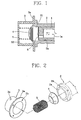
- Figures 1 and 2 are a perspective view and a longitudinal crosssectional view showing an embodiment of the axial discharge valve assembly (hereinafter, referred to as discharge valve assembly) described above.
- the discharge valve assembly comprises: a discharge cover 3 fixedly coupled to front end surface of the cylinder 2 for forming a certain discharge space S2; a discharge valve 4 of hemisphere shape which is installed in the discharge cover 3 for controlling the discharge of the compressed gas by opening/ closing the cylinder 2 ascontacted/separated to/from the front end surface of the cylinder 2 in the discharge cover 3 while the reciprocating movement of the piston 1; and a valve spring 5 supported between the discharge cover 3 and the discharge valve 4 for elastically supporting the reciprocating movement of the discharge valve 3.
- the valve spring 5 is a cylindrical compressed coil spring wound so as to have same spring constant and same rotation radius from starting portion to ending portion, and its one end is adhered to inner bottom surface of the discharge cover 3, and the other end is adhered to rear end of the discharge valve 4.
- Unexplained reference numerals 1a designates a refrigerant gas passage
- 2a is a coupling hole
- 3a is a flange unit
- 3b is a discharge hole
- 6 is a suction valve
- S1 is a compression space.
- valve spring 5 is pushed together with the discharge valve 4 during the discharge strokes of the piston 1 and compressed, and then makes the discharge valve 4 return by being stretched at a certain degree during the suction stroke of the piston 1.
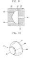
- the discharge valve 5 is fabricated using a diecasting method which injects an appropriate medium into a fixed first metal mold 7 and into a movable second metal mold 8 and presses.
- a gate through which the medium is injected is a side gate 9 or a center gate 10 formed on side unit of the discharge valve 5.
- a parting line 11 which is generated after the product is molded is formed on surface on which the first metal mold 7 and the second metal mold 8 are contacted each other.
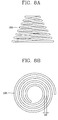
- Figure 5 is a perspective view showing the conventional discharge valve 5 formed by the above fabrication method.
- the reference numeral 12 designates a pressure face unit contacting with the cylinder 2
- the reference numeral 14 designates a pressure back face unit facing to the pressure face unit and closely supporting the one end of the valve spring 5.
- valve spring 5 is pushed to the discharge cover 3 direction with the discharge valve 4 when the compression and discharge strokes of the piston 1 are made because the cylindrical valve spring is used, and entire parts of the valve spring 5 are compressed as closely contacted with each other, whereby a part of the valve spring 5 impacts with next part and impact noise is generated.
- the coupled part of the valve spring 5 and the discharge cover 3 is free end state, an eccentric force of the valve spring 5 is generated between the inner side surface of the discharge cover 3 and the valve spring 5 having flowability in moving, and therefore the movement of the discharge valve is not concentric with the axial line or a local abrasion is generated between the two members.
- the discharge valve touches with inner wall surface of the discharge cover when the compression stroke is made, and therefore a noise and abrasion are generated.
- the discharge valve 5 is fabricated by a press method using a metal mold, and the parting line 11 is formed on the pressure face unit 12 which contacts to the front end surface of the cylinder 2. And the parting line 11 may generates a burr, and then it is contacted to the inner side surface of the discharge cover 3 when the discharge valve 5 is operated. Therefore, a noise is generated or the movement of the discharge valve 5 is not stable.
- the gate of metal mold is formed on side surface of the discharge valve 5
- the molded product may be distorted because of flowing characteristics of the injected medium and the movement of the discharge valve is not stable because of inequality in the medium density after molding, whereby the discharge noise is made.
- the gate is formed on the pressure face unit 14 direction, there is no machining allowance for post-fabrication, and therefore it is difficult to fabricate.
- US 3,5456,684 discloses a discharge valve apparatus similar to the one described before which is also suitable for a reciprocating compressor, the discharge valve apparatus comprising a discharge cover, a discharge valve and a valve spring having both ends respectively adhered to the rear surface of the discharge valve and an inner surface of the discharge cover which is facing the rear surface of the discharge valve so as to elastically supporting the rear surface of the discharge valve.
- the valve spring is formed as a conical shape in which a rotation radius is gradually reduced or increased so as to prevent a part from impacting the other parts during compression.
- a discharge valve apparatus for a reciprocating compressor comprising a discharge cover having built-in volume so as to cover front end surface of a cylinder, a discharge valve disposed so as to be contacted/separated to/from the front end surface of the cylinder by a piston which undergoes a reciprocating movement inside the cylinder, and a valve spring having both ends respectively adhered to a rear surface of the discharge valve and an inner surface of the discharge cover which is facing the rear surface of the discharge valve so as to elastically supporting the rear surface of the discharge valve, wherein the valve spring is formed as a conical shape in which a rotation radius is gradually reduced or increased so as to prevent a part from impacting to other parts during compression wherein at least one stepped unit is formed inside the discharge cover, and therefore the front end of the valve spring is not contacted to the inner wall of the discharge cover, whereby abrasion generation is prevented, wherein the discharge valve comprises a plane pressure face unit which is adhered to the front end surface of the cylinder
- a discharge valve apparatus for a reciprocating compressor comprises: a discharge cover 103 fixedly installed on a certain discharge space S2 which is disposed on front end surface of a cylinder 2 so as to cover the front end surface of the cylinder 2 in which a piston 1 is inserted; a discharge valve 104 disposed inner side of the discharge cove 103 for opening/closing the cylinder 2 by being contacted/separated to/from the front end surface of the cylinder 2 when the piston 1 undergoes a reciprocating movement; and a valve spring 105 having both ends supported by inner surface of the discharge cover 103 and by rear surface of the discharge valve 104 facing to the inner surface of the discharge cover 103.
- the discharge cover 103 is formed as a hat having a flange unit 103a including a coupling hole 103b on an opened side so as to be coupled to a flange unit 2a on the front end surface of the cylinder 2 using a bolt, and includes a discharge space S2 larger than a diameter of the discharge valve 104 so that the discharge valve 104 can freely undergo the reciprocating movement with a certain gap d1 between the outer circumferential surface of the discharge valve 104.
- a first stepped unit 103d is formed on a part where the inner side surface 103f and the inner wall surface 103g of the discharge cover 103 are closed together in the discharge cover 103, and therefore an abrasion which may be generated by impact of the front end of the valve spring 105 to the inner wall surface 103g of the discharge cover 103 can be prevented.
- a second stepped unit 103e next to the first stepped unit 103d is formed, and end of the valve spring 105 is inserted therein.
- the discharge valve 104 is formed as a hemisphere. And a pressure face unit 104a in the discharge valve 104 is contacted/separated to/from the front end surface of the cylinder 2, and one end of the valve spring 105 is adhered to a spring insert unit 104c of the pressure back face unit 104b.
- the spring insert unit 104c has a vertical portion 104d and a horizontal portion 104e, and thereby the spring insert unit 104c is forcedly inserted into the front end of the valve spring 105 when the discharge valve 104 is operated. Therefore, a structure of not escaping from the valve spring 105 is made.
- an under cutting surface unit 104f of taper shape next to the pressure face unit 104a is formed on the pressure back face unit 104b.
- the ejecting of the discharge valve molding is easy when the discharge valve is fabricated, and a damage on the metal mold can be prevented.
- the outer diameter of the discharge valve 104 smaller than the inner diameter of the discharge cover 103 by more than1 mm. Then, a flowing resistance during the linear reciprocating movement of the discharge valve 104 and the abrasion by the contact with the discharge cover 103 caused by the eccentric force of the valve spring 105 can be prevented.
- valve spring 105 is a compressed coil spring of conical shape having one end closely supported by the second stepped unit 103d formed on inner side surface of the discharge cover 103, and the other end inserted into the spring insert unit 104c of the discharge valve 104.
- valve spring 105 is formed as a conical type in which the rotation radius is gradually reduced or increased so as to prevent a part from impacting to next parts during compression.
- winding number of the wire which is an important element in deciding elastic force is decided according to a noise characteristic and a pressure dispersion inside the discharge cover.
- the wire is wound more than twice in order to prevent the generation of the eccentric force caused by biased application of the elastic force to opened end direction of the valve spring 105, and in order to make the elastic force be applied equally.
- it is desirable that the wire is wound 2.3 times in real application. And accordingly, the moving instability of the discharge valve 104 can be solved.
- valve spring 105 is formed to have a certain gap d2 between the respective wire of the valve spring 105 when the valve spring 105 is projected on the inner wall surface 103g of the discharge cover.
- a wound rotation center of the valve spring 105 and the center of the discharge valve 104 are on same axial line.
- a broad end part of the valve spring 105 may be supported by the inner side of the discharge cover 3, and a small end part of the valve spring may be supported by the discharge valve 104.
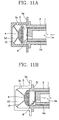
- the discharge valve 104 is injection molded through a fixed first metal mold 107 on which a contour making the pressure face unit 112 of the discharge valve 104 is formed, and a second metal mold 108 on which a contour making the pressure back face unit 114 of the discharge valve 104 and the cutting surface unit 116 is formed.
- a parting line 111 is formed between the pressure face unit 112 and the pressure back face unit 114 of the discharge valve 104.
- a part where the contour of the pressure back face unit 114 meets the parting line 111 becomes an under cutting surface 116 which is slightly slanted, and therefore the discharge valve molding is separated as adhering to the movable second metal mold 108 when the metal molds are separated.
- the discharge valve molding is ejected by a plurality of eject pins 115 formed on inside of the second metal mold 108.
- a gate through which the medium is injected is formed on the first metal mold 107 having the contour of the pressure surface unit 112 of the discharge valve 104.
- the unexplained reference numerals 1 a designates a refrigerant gas passage
- 2a is a penetrating hole
- 2b is a coupling hole
- a S1 designates a compression space.
- a new refrigerant gas is sucked through the refrigerant gas passage 1 a in the piston 1, compressed in the compression space S1 as pushing the suction valve 6 installed on the front end surface of the piston 1, and discharged to the discharge space S2 at a certain time point during the suction stroke of the piston 1.
- the sucked gas filled in the compression space S1 of the cylinder 2 is compressed by being pushed by the piston 1, and discharged to the discharge space S2 as pushing the discharge valve 104 during the compression and discharge strokes of the piston 1.
- the compressed gas filled in the discharge space S2 is discharged out of the discharge valve assembly being pushed by newly sucked gas during the next compression and discharge strokes of the piston 1.
- the pressure in the compression space S1 is smaller than the elastic force of the valve spring 105 during the suction stroke of the piston 1, and therefore the valve spring is returned and the discharge valve 104 is adhered to the front end surface of the cylinder 2.
- the pressure in the compression space S1 is larger than the elastic force of the valve spring 105 during the compression and discharge strokes of the piston1, and therefore the discharge valve 104 is pushed and the valve spring 105 is compressed.
- the rotation radius of the valve spring 105 is gradually reduced from the discharge cover 103 toward the discharge valve 104 so that a part is not contacted to the other parts, and therefore the noise caused by impacts of respective parts during compression can be prevented.
- the rotation radius of the valve spring is set to be gradually reduced or increased, and then impacts of a part to the other parts is prevented by using or stepped unit (103d ; 103e) inside the discharge cover, whereby the impact noise caused by the impacts of the respective during the compression of the valve spring in accordance with the compression and discharge strokes of the piston can be prevented.
- one or more stepped units are formed on the discharge cover side where the valve spring is coupled, and therefore the valve spring is closely supported. And then, the eccentric force which may be generated by the continued reciprocating movements of the valve spring can be prevented.
- the parting line is formed on center part of the discharge valve and the gate is formed on fixed metal mold which used for fabricating the discharge valve, and therefore the ejecting of the discharge valve becomes easy and the post-fabrication becomes easy because of the characteristic of the discharge valve shape.
- a life span of the metal mold is increased, and generation of the burr can be prevented.
- the fabrication metal mold is easy to be ejected when the discharge valve is fabricated by forming an undercutting surface which is tapered. And, the vertical portion and the horizontal portion of same diameter as the inner diameter of the spring are formed on the spring insert unit, whereby the abrasion of the discharge valve caused by the repeated movements can be prevented.
Claims (12)
- Appareil à clapet de refoulement pour un compresseur volumétrique à pistons comprenant:un couvercle de refoulement (103) ayant un volume intégré de manière à recouvrir la surface d'extrémité frontale d'un cylindre (2);un clapet de refoulement (104) disposé de manière à entrer en contact avec/être séparé de la surface d'extrémité frontale du cylindre (2) par un piston (1) qui subit un mouvement alternatif à l'intérieur du cylindre (2); etun ressort de clapet (105) ayant les deux extrémités adhérant respectivement à une surface arrière du clapet de refoulement (104) et à une surface interne du couvercle de refoulement (103) qui est en face de la surface arrière du clapet de refoulement (104) de manière à supporter élastiquement la surface arrière du clapet de refoulement (104), dans lequel le ressort de clapet (105) est réalisé de forme conique dans laquelle un rayon de rotation est réduit ou augmenté graduellement pour éviter une partie de faire impact avec les autres parties pendant la compression, caractérisé en ce que au moins une unité étagée (103d; 103e) est ménagée à l'intérieur du couvercle de refoulement (103) et par conséquent, l'extrémité frontale du ressort de clapet (105) n'est pas en contact avec la paroi interne du couvercle de refoulement (103), la génération de l'abrasion étant évitée, dans lequel le clapet de refoulement (104) comprend:une unité plane de face de pression (104a) qui adhère à la surface frontale d'extrémité du cylindre (2); etune unité de face de contre-pression (104b) qui est réalisée saillante sur le côté opposé à l'unité de face de pression (104a) de sorte que son diamètre est réduit graduellement depuis le bord en direction centrée.
- Appareil de la revendication 1, dans lequel le ressort de clapet (105) est entouré plus que deux fois.
- Appareil de la revendication 1, dans lequel une unité étagée (103e) dans laquelle une extrémité du ressort de clapet (105) est insérée, est formée dans la continuité de l'unité étagée (103d).
- Appareil de la revendication 1, dans lequel un certain intervalle (d2) est formé entre des fils du ressort de clapet (105) quand le ressort de clapet (105) est projeté sur la paroi interne du couvercle de refoulement (103).
- Appareil de la revendication 1, dans lequel un centre de ressort de clapet (105) et un centre du clapet de refoulement (104) sont sur la même ligne axiale.
- Appareil de la revendication 1, dans lequel un intervalle (d1) entre un diamètre externe du clapet de refoulement (104) et un diamètre interne de couvercle de refoulement (103) est supérieur à 1 mm.
- Appareil de la revendication 1, dans lequel une ligne de joint (111) est formée à une position où la face de pression (112) rencontre la face de contre-pression (114).
- Appareil de la revendication 1, dans lequel le clapet de refoulement (104) comprend une unité de surface de dégagement (116) formée en biais par rapport à au moins l'une des faces de pression (112) et de contre-pression (114).
- Appareil de la revendication 1, dans lequel l'unité de face de contre-pression (104b) comprend en outre une unité d'insertion de ressort (104c) de manière à être insérée de force dans le ressort de clapet (105).
- Appareil de la revendication 9, dans lequel l'unité d'insertion de ressort (104c) comprend une portion verticale (104d) et une portion horizontale (104e).
- Appareil de la revendication 1, dans lequel une passerelle (110) est formée sur un moule métallique fixe (107) sur lequel l'unité de face de pression (112) est moulée quand le clapet de refoulement (104) est fabriqué par un procédé de moulage par injection.
- Appareil de la revendication 1, dans lequel une pluralité de broches d'éjection (115) sont formées sur un moule de métal mobile (108) sur laquelle l'unité de face de contre-pression (114) est formée quand le clapet de refoulement (104) est fabriqué par un procédé de moulage par injection.
Applications Claiming Priority (3)
| Application Number | Priority Date | Filing Date | Title |
|---|---|---|---|
| KR1020000029045A KR100341477B1 (ko) | 2000-05-29 | 2000-05-29 | 토출밸브 조립체의 소음 저감구조 |
| KR2000029045 | 2000-05-29 | ||
| PCT/KR2001/000827 WO2001092722A1 (fr) | 2000-05-29 | 2001-05-19 | Appareil a clapet de refoulement pour compresseur volumetrique a pistons |
Publications (3)
| Publication Number | Publication Date |
|---|---|
| EP1285166A1 EP1285166A1 (fr) | 2003-02-26 |
| EP1285166A4 EP1285166A4 (fr) | 2005-10-26 |
| EP1285166B1 true EP1285166B1 (fr) | 2010-02-24 |
Family
ID=19670706
Family Applications (1)
| Application Number | Title | Priority Date | Filing Date |
|---|---|---|---|
| EP20010932372 Expired - Lifetime EP1285166B1 (fr) | 2000-05-29 | 2001-05-19 | Appareil a clapet de refoulement pour compresseur volumetrique a pistons |
Country Status (9)
| Country | Link |
|---|---|
| US (1) | US7056106B2 (fr) |
| EP (1) | EP1285166B1 (fr) |
| JP (1) | JP2003535270A (fr) |
| KR (1) | KR100341477B1 (fr) |
| CN (1) | CN1246584C (fr) |
| AU (1) | AU5890101A (fr) |
| BR (1) | BR0106706B1 (fr) |
| DE (1) | DE60141394D1 (fr) |
| WO (1) | WO2001092722A1 (fr) |
Families Citing this family (15)
| Publication number | Priority date | Publication date | Assignee | Title |
|---|---|---|---|---|
| CN100375839C (zh) * | 2003-05-20 | 2008-03-19 | 乐金电子(天津)电器有限公司 | 往复式压缩机的排出装置 |
| CN100424349C (zh) * | 2003-06-17 | 2008-10-08 | 乐金电子(天津)电器有限公司 | 往复式压缩机的排出阀组件 |
| US7275561B2 (en) * | 2003-10-31 | 2007-10-02 | Lg Electronics Inc. | Discharging valve assembly of reciprocating compressor |
| CN100414105C (zh) * | 2003-11-27 | 2008-08-27 | Lg电子株式会社 | 往复式压缩机的排气阀组件 |
| KR100613514B1 (ko) * | 2004-10-07 | 2006-08-17 | 엘지전자 주식회사 | 리니어 압축기의 토출부 구조 |
| US7766036B2 (en) * | 2004-11-12 | 2010-08-03 | Lg Electronics Inc. | Discharge valve and valve assembly of reciprocating compressor having the same |
| AR053113A1 (es) * | 2006-01-04 | 2007-04-25 | Juan G Kippes | Motor a vapor con caldera por conveccion. |
| KR100714577B1 (ko) * | 2006-01-16 | 2007-05-07 | 엘지전자 주식회사 | 리니어 압축기의 토출밸브 어셈블리 |
| JP5617402B2 (ja) * | 2010-07-15 | 2014-11-05 | パナソニック株式会社 | 往復式圧縮機およびこれを用いた冷蔵庫 |
| CN102644582A (zh) * | 2011-02-16 | 2012-08-22 | 广东美芝制冷设备有限公司 | 压缩机的排气装置 |
| BRPI1103447A2 (pt) * | 2011-07-19 | 2013-07-09 | Whirlpool Sa | feixe de molas para compressor e compressor provido de feixe de molas |
| CN103672061A (zh) * | 2012-09-03 | 2014-03-26 | 珠海格力节能环保制冷技术研究中心有限公司 | 排气阀 |
| CN106481534B (zh) * | 2015-08-24 | 2019-04-02 | 珠海格力节能环保制冷技术研究中心有限公司 | 空调器、压缩机及其排气机构 |
| CN107795461A (zh) * | 2017-10-20 | 2018-03-13 | 珠海凌达压缩机有限公司 | 压缩机的排气结构及压缩机 |
| CN115591139A (zh) * | 2021-12-29 | 2023-01-13 | 罗钢(Cn) | 高原辅助呼吸装置 |
Family Cites Families (30)
| Publication number | Priority date | Publication date | Assignee | Title |
|---|---|---|---|---|
| US851358A (en) * | 1905-12-08 | 1907-04-23 | Clemens Kiesselbach | Valve. |
| US1951215A (en) * | 1932-01-21 | 1934-03-13 | Bryce Ltd | Fuel pump |
| US2258426A (en) * | 1938-10-26 | 1941-10-07 | Gen Motors Corp | Refrigerating apparatus |
| US2600554A (en) * | 1949-09-16 | 1952-06-17 | Allan J Lyons | Sprinkler |
| AT239426B (de) * | 1963-07-04 | 1965-04-12 | Enfo Grundlagen Forschungs Ag | Selbsttätiges Ventil, insbesondere für Kolbenverdichter |
| US3406715A (en) * | 1965-10-04 | 1968-10-22 | Rain Jet Corp | Drain valve |
| US3811470A (en) * | 1971-06-01 | 1974-05-21 | J Schaefer | Fluid control device |
| US4212316A (en) * | 1978-03-13 | 1980-07-15 | Acf Industries, Incorporated | Control valve |
| JPS5917305B2 (ja) * | 1978-12-19 | 1984-04-20 | 日信工業株式会社 | 逆止弁付ホ−ス |
| JPS5951177A (ja) * | 1982-09-17 | 1984-03-24 | Matsushita Electric Ind Co Ltd | 圧縮機の給油装置 |
| JPS5954785A (ja) * | 1982-09-20 | 1984-03-29 | Matsushita Electric Ind Co Ltd | 圧縮機の給油装置 |
| JPS63183278A (ja) * | 1987-01-26 | 1988-07-28 | Matsushita Electric Ind Co Ltd | 圧縮機 |
| JPH04134192A (ja) * | 1990-09-27 | 1992-05-08 | Brother Ind Ltd | 往復動圧縮機 |
| KR0136611Y1 (ko) * | 1995-08-16 | 1999-03-20 | 구자홍 | 리니어 압축기의 밸브장치 |
| KR0176827B1 (ko) * | 1995-08-21 | 1999-10-01 | 구자홍 | 리니어 압축기의 흡입 밸브 고정구조 |
| CN1066246C (zh) * | 1995-08-21 | 2001-05-23 | Lg电子株式会社 | 线性压缩机用的轴向流动阀系统 |
| KR200141770Y1 (ko) * | 1995-08-31 | 1999-05-15 | 이형도 | 모터의 자기저항소자 조정장치 |
| KR0176911B1 (ko) * | 1996-05-08 | 1999-10-01 | 구자홍 | 리니어 압축기의 헤드커버 마멸방지장치 |
| KR0176913B1 (ko) * | 1996-05-08 | 1999-10-01 | 구자홍 | 리니어 압축기의 실린더 충격흡수장치 |
| US5984652A (en) * | 1997-06-17 | 1999-11-16 | Oil-Rite Corporation | Single-piece piston with central bore for use in a pneumatically-activated pump |
| KR19990016945A (ko) | 1997-08-20 | 1999-03-15 | 구자홍 | 리니어 압축기의 토출장치 |
| KR100284429B1 (ko) | 1998-11-11 | 2001-04-02 | 구자홍 | 밸브 조립체 |
| KR100273452B1 (ko) | 1998-12-05 | 2000-12-15 | 구자홍 | 토출밸브 조립체 |
| KR20000038301A (ko) | 1998-12-05 | 2000-07-05 | 구자홍 | 토출밸브 조립체의 밸브스프링 지지구조 |
| KR100311377B1 (ko) | 1998-12-05 | 2001-12-20 | 구자홍 | 밸브조립체의가스댐핑구조 |
| KR100292513B1 (ko) | 1998-12-05 | 2001-11-15 | 구자홍 | 토출밸브조립체 |
| KR100311379B1 (ko) | 1998-12-09 | 2001-12-12 | 구자홍 | 밸브조립체의댐핑장치 |
| KR100311378B1 (ko) | 1998-12-09 | 2001-12-12 | 구자홍 | 토출밸브조립체 |
| KR100273462B1 (ko) | 1998-12-31 | 2000-12-15 | 구자홍 | 토출밸브 조립체 |
| KR100314062B1 (ko) | 1999-09-08 | 2001-11-15 | 구자홍 | 토출밸브 조립체 |
-
2000
- 2000-05-29 KR KR1020000029045A patent/KR100341477B1/ko active IP Right Grant
-
2001
- 2001-05-19 US US10/048,020 patent/US7056106B2/en not_active Expired - Lifetime
- 2001-05-19 JP JP2002500103A patent/JP2003535270A/ja active Pending
- 2001-05-19 EP EP20010932372 patent/EP1285166B1/fr not_active Expired - Lifetime
- 2001-05-19 WO PCT/KR2001/000827 patent/WO2001092722A1/fr active Application Filing
- 2001-05-19 CN CNB018014577A patent/CN1246584C/zh not_active Expired - Lifetime
- 2001-05-19 AU AU58901/01A patent/AU5890101A/en not_active Abandoned
- 2001-05-19 BR BRPI0106706-0A patent/BR0106706B1/pt not_active IP Right Cessation
- 2001-05-19 DE DE60141394T patent/DE60141394D1/de not_active Expired - Lifetime
Also Published As
| Publication number | Publication date |
|---|---|
| US7056106B2 (en) | 2006-06-06 |
| EP1285166A1 (fr) | 2003-02-26 |
| BR0106706A (pt) | 2002-04-30 |
| US20020150488A1 (en) | 2002-10-17 |
| JP2003535270A (ja) | 2003-11-25 |
| EP1285166A4 (fr) | 2005-10-26 |
| CN1246584C (zh) | 2006-03-22 |
| KR20010108562A (ko) | 2001-12-08 |
| BR0106706B1 (pt) | 2009-08-11 |
| DE60141394D1 (fr) | 2010-04-08 |
| AU5890101A (en) | 2001-12-11 |
| KR100341477B1 (ko) | 2002-06-21 |
| CN1380945A (zh) | 2002-11-20 |
| WO2001092722A1 (fr) | 2001-12-06 |
Similar Documents
| Publication | Publication Date | Title |
|---|---|---|
| EP1285166B1 (fr) | Appareil a clapet de refoulement pour compresseur volumetrique a pistons | |
| EP1923143B1 (fr) | Dispositif de décharge de liquides de type gâchette | |
| KR100752745B1 (ko) | 인서트 천 사출금형 장치 | |
| JP3111015B2 (ja) | 射出・圧縮成形用金型 | |
| CN219600295U (zh) | 应用于具有倒钩部产品的镶件回位装置及模具 | |
| US11794393B2 (en) | Abrupt ejector plate stop | |
| CN116160626B (zh) | 一种洗衣机旋钮的注塑模具 | |
| JP2000102953A (ja) | 射出成形用金型 | |
| CN220031042U (zh) | 一种三头滑块 | |
| CN109774080B (zh) | 一种模具组件 | |
| CN219944573U (zh) | 结构简单且可方便调节推出力度的推出结构及压铸模具 | |
| CN217270782U (zh) | 一种高压清洗机柱塞泵 | |
| CN219402273U (zh) | 压铸模具顶出机构及铸造模具 | |
| CN218906183U (zh) | 一种注塑模用油缸抽芯结构 | |
| CN219543924U (zh) | 一种注塑顶出结构 | |
| CN220372208U (zh) | 一种钛合金粉末射出成型模具脱模机构 | |
| CN217881264U (zh) | 一种防冲击装置及行程开关 | |
| CN217415019U (zh) | 物料压制设备上模组件 | |
| CN218080266U (zh) | 一种水套型芯模具 | |
| KR100292506B1 (ko) | 리니어압축기 | |
| KR20240022096A (ko) | 다이 캐스팅용 이젝팅 장치 | |
| JPH10141231A (ja) | 圧縮機用バルブアセンブリー | |
| KR100503775B1 (ko) | 스위치용푸쉬로드성형방법 | |
| CN113146976A (zh) | 一种蓄电池电池盖注塑模具顶杆配合结构 | |
| KR100504855B1 (ko) | 압축기용 밸브 |
Legal Events
| Date | Code | Title | Description |
|---|---|---|---|
| PUAI | Public reference made under article 153(3) epc to a published international application that has entered the european phase |
Free format text: ORIGINAL CODE: 0009012 |
|
| 17P | Request for examination filed |
Effective date: 20020221 |
|
| AK | Designated contracting states |
Kind code of ref document: A1 Designated state(s): AT BE CH CY DE DK ES FI FR GB GR IE IT LI LU MC NL PT SE TR |
|
| AX | Request for extension of the european patent |
Extension state: AL LT LV MK RO SI |
|
| RBV | Designated contracting states (corrected) |
Designated state(s): DE IT |
|
| A4 | Supplementary search report drawn up and despatched |
Effective date: 20050909 |
|
| RIC1 | Information provided on ipc code assigned before grant |
Ipc: 7F 04B 39/10 B Ipc: 7F 04B 17/04 A |
|
| 17Q | First examination report despatched |
Effective date: 20060201 |
|
| GRAP | Despatch of communication of intention to grant a patent |
Free format text: ORIGINAL CODE: EPIDOSNIGR1 |
|
| GRAS | Grant fee paid |
Free format text: ORIGINAL CODE: EPIDOSNIGR3 |
|
| GRAA | (expected) grant |
Free format text: ORIGINAL CODE: 0009210 |
|
| AK | Designated contracting states |
Kind code of ref document: B1 Designated state(s): DE IT |
|
| REF | Corresponds to: |
Ref document number: 60141394 Country of ref document: DE Date of ref document: 20100408 Kind code of ref document: P |
|
| PLBE | No opposition filed within time limit |
Free format text: ORIGINAL CODE: 0009261 |
|
| STAA | Information on the status of an ep patent application or granted ep patent |
Free format text: STATUS: NO OPPOSITION FILED WITHIN TIME LIMIT |
|
| 26N | No opposition filed |
Effective date: 20101125 |
|
| PG25 | Lapsed in a contracting state [announced via postgrant information from national office to epo] |
Ref country code: IT Free format text: LAPSE BECAUSE OF FAILURE TO SUBMIT A TRANSLATION OF THE DESCRIPTION OR TO PAY THE FEE WITHIN THE PRESCRIBED TIME-LIMIT Effective date: 20100224 |
|
| PGFP | Annual fee paid to national office [announced via postgrant information from national office to epo] |
Ref country code: DE Payment date: 20200406 Year of fee payment: 20 |
|
| REG | Reference to a national code |
Ref country code: DE Ref legal event code: R071 Ref document number: 60141394 Country of ref document: DE |