EP1283507A1 - Warenschleuse und Verfahren zum Betrieb einer solchen Warenschleuse - Google Patents
Warenschleuse und Verfahren zum Betrieb einer solchen Warenschleuse Download PDFInfo
- Publication number
- EP1283507A1 EP1283507A1 EP01810765A EP01810765A EP1283507A1 EP 1283507 A1 EP1283507 A1 EP 1283507A1 EP 01810765 A EP01810765 A EP 01810765A EP 01810765 A EP01810765 A EP 01810765A EP 1283507 A1 EP1283507 A1 EP 1283507A1
- Authority
- EP
- European Patent Office
- Prior art keywords
- opening
- goods
- goods lock
- lock according
- conveying space
- Prior art date
- Legal status (The legal status is an assumption and is not a legal conclusion. Google has not performed a legal analysis and makes no representation as to the accuracy of the status listed.)
- Granted
Links
- 238000000034 method Methods 0.000 title claims description 13
- 230000001681 protective effect Effects 0.000 claims description 3
- 238000007599 discharging Methods 0.000 claims description 2
- 238000011017 operating method Methods 0.000 abstract description 3
- 238000004519 manufacturing process Methods 0.000 description 3
- 235000013361 beverage Nutrition 0.000 description 2
- 230000033001 locomotion Effects 0.000 description 2
- 238000005192 partition Methods 0.000 description 2
- 241001465754 Metazoa Species 0.000 description 1
- 208000027418 Wounds and injury Diseases 0.000 description 1
- 238000010276 construction Methods 0.000 description 1
- 230000006378 damage Effects 0.000 description 1
- 230000003247 decreasing effect Effects 0.000 description 1
- 230000001419 dependent effect Effects 0.000 description 1
- 238000011161 development Methods 0.000 description 1
- 230000018109 developmental process Effects 0.000 description 1
- 230000008595 infiltration Effects 0.000 description 1
- 238000001764 infiltration Methods 0.000 description 1
- 208000014674 injury Diseases 0.000 description 1
- 238000004806 packaging method and process Methods 0.000 description 1
- 230000035515 penetration Effects 0.000 description 1
- 238000005086 pumping Methods 0.000 description 1
- 238000000926 separation method Methods 0.000 description 1
Images



Classifications
-
- G—PHYSICS
- G07—CHECKING-DEVICES
- G07F—COIN-FREED OR LIKE APPARATUS
- G07F11/00—Coin-freed apparatus for dispensing, or the like, discrete articles
- G07F11/46—Coin-freed apparatus for dispensing, or the like, discrete articles from movable storage containers or supports
- G07F11/50—Coin-freed apparatus for dispensing, or the like, discrete articles from movable storage containers or supports the storage containers or supports being rotatably mounted
- G07F11/54—Coin-freed apparatus for dispensing, or the like, discrete articles from movable storage containers or supports the storage containers or supports being rotatably mounted about vertical axes
-
- G—PHYSICS
- G07—CHECKING-DEVICES
- G07F—COIN-FREED OR LIKE APPARATUS
- G07F11/00—Coin-freed apparatus for dispensing, or the like, discrete articles
- G07F11/02—Coin-freed apparatus for dispensing, or the like, discrete articles from non-movable magazines
- G07F11/04—Coin-freed apparatus for dispensing, or the like, discrete articles from non-movable magazines in which magazines the articles are stored one vertically above the other
- G07F11/16—Delivery means
- G07F11/24—Rotary or oscillatory members
-
- E—FIXED CONSTRUCTIONS
- E05—LOCKS; KEYS; WINDOW OR DOOR FITTINGS; SAFES
- E05G—SAFES OR STRONG-ROOMS FOR VALUABLES; BANK PROTECTION DEVICES; SAFETY TRANSACTION PARTITIONS
- E05G7/00—Safety transaction partitions, e.g. movable pay-plates; Bank drive-up windows
- E05G7/002—Security barriers for bank teller windows
- E05G7/005—Pass-boxes therefor, e.g. with stationary bottoms
- E05G7/007—Pass-boxes therefor, e.g. with stationary bottoms with rotatable bottoms
Definitions
- the invention relates to a goods lock and a Method for operating such a goods lock according to claims 1 and 13, respectively.
- DE 23 45 177 describes a lock for the automatic delivery of goods, in particular Bottle crates.
- the lock has a lock channel that can be closed on both sides by gates. During the Removing goods is one of the gates closed.
- the well-known lock has several Disadvantages.
- the separation device and that Lock principle are not suitable for a broad Spectrum of different sizes as well differently packaged goods. There are Pinching risks for the user. After all, it is possible from the outside into the lock room and through the Lock channel to get to the goods magazine.
- the output device described in DE 36 06 268 is designed for a goods shaft.
- the underlying Principle is only for size and Suitable for packaging standardized goods.
- the Locking the dispensing opening is relatively complicated and thus prone to interference and possibly Vandalism.
- the invention is therefore based on the object Goods lock and an operating method therefor To make available with the objects of all kinds, especially voluminous or fragile goods quickly, easily and in a controlled manner can.
- the process flow for the user be harmless (handling safety), simple, run quickly and reliably (operational safety) and Possible external influences on the storage area can be reduced, in particular penetration into the Storage area can be prevented (abuse resistance).
- the goods lock according to the invention comprises at least one Output window and at least one funding area, preferably to increase the clock frequency two or more Delivery spaces.
- the output window is in a Wall that usually covers the storage area to be secured separates public output area.
- the conveying space between a loading position and one Unloading position movable.
- the funding room has at least an opening that can be discharged into the area of a Output window is brought (unloading position). She is preferably largely with a closing element completely lockable and will be after discharge and closed before moving the delivery room. This will reduce the risk of getting into the outside Intervention area is intervened and that the user injured when removing the pumping chamber.
- the closing element preferably provides one movable wall of the delivery space, e.g. whose the Opening opposite rear wall. When discharging the volume of the delivery space gradually decreased to one Objects remain in the delivery area or penetrate to prevent in the delivery room.
- the closing element is preferably in one direction essentially movable perpendicular to the opening, e.g. longitudinal a delivery room designed as a delivery channel.
- a conveyor mechanism e.g. on Conveyor belt on the floor of the conveyor room. This can also be formed by the closing element itself, which the For example, pushes out object.
- the closing element can Funding area can be directly assigned, e.g. by a slidable rear wall may be formed, or capable be to serve several funding rooms.
- the closing element engages in the unloading position Funding area and closes its opening after the Discharged.
- the movement of the conveying spaces preferably takes place between the loading and unloading position in horizontal Direction, since no weight forces are overcome have to.
- the at least one is particularly preferred By rotating between the different Move positions. He can do this on or in one Rotary body may be arranged, preferably around a vertical axis is rotated.
- the inventive method for operating such Goods lock provides that a conveyor room in the area positioned at a loading position and there with few an object is loaded into a Unloading position is moved where the at least one Object, for example by means of the closing element or an additional conveyor mechanism for unloading the delivery room is ejected.
- the at least one Object for example by means of the closing element or an additional conveyor mechanism for unloading the delivery room is ejected.
- the goods lock according to the invention and the one according to the invention Procedure for intrusion resistant dispensing of Objects offers a technical solution for the cases where a wide range of different, in particular also from voluminous objects a closed or not freely accessible area spent, intrusion and access options, however should be prevented at the same time. That is relevant Problem mainly, but not only, with Vending machines.
- the sale or issue of Objects by a vending machine or the like Device is automatic and not human supervised. But it is also conceivable to turn on the goods lock operated output terminals to install.
- Figure 1 shows a three-dimensional view of a goods lock 1
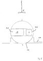
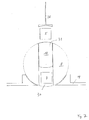
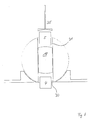
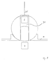
- FIGS. 2 to 9 show sectional views same goods lock 1 in different positions at Entry and / or exit of objects 4.
- the goods lock 1 forms the connecting element between a protected or closed, i.e. for the Buyer or recipient or buyer of items to be issued inaccessible inner area 2 and one for the buyers or recipients or buyers are freely accessible Outside area 6. Both areas are separated by a partition 14 separated in the area of a transfer point 7 for the goods to be discharged has an output window 12. in the inner area 2 is at least one loading position 3, on the objects to be discharged 4, 5 the goods lock 1 are handed over. you will be for example with a belt conveyor, not shown here brought into the loading position 3.
- the goods lock 1 has a wheel-like rotating body 8 a continuous, horizontal, cross-section rectangular lock channel 15, the ends of which Form funding rooms 30, 31.
- the axis of the rotating body 8 runs vertically.
- the rotating body can also be used on others Formed in a manner as exemplified in FIG. 10 is shown.
- the two opposite openings 9, 10 of the lock channel 15 are used for the introduction and discharge of objects into and out of the assigned funding space 30, 31.
- the rotating body 8 includes one except for the openings 9, 10 full-surface lateral surface 11, partially through the output window 12 protrudes.
- the output window 12 is laterally provided with wipers 13.
- the lock channel 15 runs through the center of the rotating body 8. Seine lateral boundary is formed by surfaces 16, 17.
- a piston element 18 in the Lock channel 15 is a piston element 18, the by means of a suitable drive, not shown here in the Lock channel 15 slidable in the horizontal direction is.
- the piston element 18 has the function of the lock channel 15 permanent, but at variable positions block and so the funding rooms 30, 31 for admission to release an object or to the outside complete and if necessary the subject eject.
- the two arranged in the channel direction Sides of the piston member 18 have the function of Closing elements 32, 33.
- the lock channel 15 is not continuous Approved. In the simplest variant, that separates Piston element 18 the lock channel in two delivery rooms 30, 31, each depending on its position Volume from 0 to 100 percent of the lock channel minus the space requirement of the piston element 18 can.
- the openings 9, 10 facing as Closing elements 32, 33 functioning sides are corresponding the radius of the rotating body curved to the Openings in the lateral surface 11 of the rotating body 8 to be able to close as perfectly as possible.
- the piston member 18 has a length that is slightly is greater than the radius of the rotating body 8. This has the Advantage that the piston element 18 with a single, protected within the piston element 18 in the area of Center of rotation arranged drive can be moved which among other things the handling and operational safety is increased.
- the drive includes, for example a gear that is integrated in a piston element 18 Toothed rack engages.
- the piston element is as narrow as possible. This has the advantage that with a rotating body with a given larger radius, a larger delivery space is formed.
- the partition wall 14 has protective walls 36 which extend laterally starting from the output window 13 to the lateral surface 11 of the rotating body. Through this essentially wedge-shaped or circular segment-like shape of the Protective walls 36 is the risk of injury when turning the Avoided rotating body, which otherwise when gripping through the output window exists.
- the goods lock 1 is preferred operated as follows: In the standby position (Fig. 3) is one of the conveying spaces 30 at the loading position 3 and the opposite delivery area on the Unloading position 7.
- the delivery space 31 is shown in the Example completely by the piston element 18 filled in, its opening 10 is closed.
- piston element 18 can also be the opposite one Close opening 9 and the delivery chamber 31 completely release.
- the position shown in Fig. 3 is particularly useful if the person to be smuggled in Item 4 with a conveyor mechanism in the channel direction is moved, regardless of the drive of the piston element 18 is.
- a slide 35 pushes the Item 4 in the funding room 30.
- the Piston element 18 connected to conveyor belts 29 and are driven by these.
- the conveyor belts 29 can integrated into the walls of the lock channel, for example be and simultaneously in and out support. Moved when inserting the object 4 the piston element 18 to the center of rotation and there gradually the funding room 30 free. In this case is the piston element 18 in the Ready position on the opposite side of the Rotary body, the delivery chamber 31 is initially free.
- the rotating body 8 is rotated so that the conveying space 30 is the intermediate position shown in FIG. 6 arrives at the output window 12 (FIG. 7). If this position of the rotating body 8 is reached, it will Piston element 18 through the lock channel 15 on the other side moves. Item 4 or items in the relevant funding area 30 are removed and the Opening 9 of the delivery chamber 30 closed. simultaneously can already the next in the other funding room 31 Goods 5 'to be discharged into the lock channel 15 brought (Fig. 8 and 9). If no other goods can be discharged, the rotating body 8 in one Rest position are rotated so that the outer surface of the Revolving body blocked the output window 12 (Fig. 2).
- the funding areas are not necessarily by one continuous lock channel formed, but can also through individual, not necessarily connected to each other Recesses in the rotating body or by crossing Channels can be realized. Along the circumference of the rotating body can also be arranged three or more production rooms his. More than two funding areas allow an increase in Number of cycles and the discharge variants.
- FIG. 10 An example of a goods lock with four conveyor rooms 19, 20, 21, 22 shows FIG. 10.
- the closing elements 23, 24, 25, 26 close the funding areas 19, 20, 21, 22 either in the area of the outer surface of the rotating body 8 or the back of the conveyor area facing the turning center. Objects can thus depending on the position of the locking elements 23, 24, 25, 26 in a conveying space 19, 20, 21, 22 get, but no further in the rotating body into it.
- the closing elements 23, 24, 25, 26 opposite Delivery rooms are preferably with each other connected, e.g. by rods 27, 28, and are in pairs moved by the same drive. However, it is also possible the closing elements 23, 24, 25, 26 independently of one another to make it movable. There are also several Unloading positions possible (Fig. 10). Also one Can change direction between loading and unloading will be realized.
- the rotating body designed in a ring shape and a fixed one in the center Closing element arranged on each of the in the To access unloading brought brought conveying spaces is able.
- the conveying spaces preferably have two openings, one for loading and the other for unloading serves.
- the goods lock according to the invention can also have several different loading positions to the Clock further increase.
- the advantages of the goods lock according to the invention are one reduced expenditure of time per entry and exit process as well as the possibility of several entry and exit processes to process at the same time.
- the closing element also serves as a front door that the Secure the funding area against external interference. On structurally and functionally complex separate element can be omitted. Furthermore, it has to be introduced serving conveyor mechanism goods only over short distances move, in particular just push it into the delivery area. It can therefore be a simple and lightweight construction be chosen, the short distances allow a higher Clock sequence.
- the goods lock according to the invention has a high operational reliability because the dispensing opening through the Closing element is closed before the rotating body rotates. This increases the risk of getting caught reduced.
Landscapes
- Physics & Mathematics (AREA)
- General Physics & Mathematics (AREA)
- Vending Machines For Individual Products (AREA)
- Control Of Vending Devices And Auxiliary Devices For Vending Devices (AREA)
- Special Conveying (AREA)
Abstract
Description
- Fig. 1
- eine dreidimensionale Ansicht einer erfindungsgemässe Warenschleuse mit einem in eine aufgeschnittene Wand eingebauten Ausgabefenster;
- Fig. 2
- einen Schnitt durch eine Warenschleuse mit zwei drehbaren Förderräumen in Ruhestellung;
- Fig. 3
- einen Schnitt durch die Warenschleuse nach Fig. 2 in Bereitschaftsstellung;
- Fig. 4, 5
- einen Schnitt durch die Warenschleuse nach Fig. 2 während der Einschleusung eines Gegenstands;
- Fig. 6
- einen Schnitt durch die Warenschleuse nach Fig. 2 im Verlauf der Drehung in die Entladeposition;
- Fig. 7
- einen Schnitt durch die Warenschleuse nach Fig. 2 während der Ausschleusung eines Gegenstandes;
- Fig. 8, 9
- einen Schnitt durch eine Warenschleuse während der Aus- und gleichzeitigen Einschleusung eines Gegenstands;
- Fig. 10
- einen Schnitt durch eine Warenschleuse mit vier Förderräumen.
Claims (15)
- Warenschleuse (1) zum Ausschleusen von Gegenständen (4, 5) mit wenigstens einem Ausgabefenster 812), wenigstens einem Förderraum (19, 20, 21, 22, 30, 31) und wenigstens einem Schliesselement (23, 24, 25, 26, 32, 33), wobei der Förderraum wenigstens eine Öffnung (9, 10) aufweist, durch die ein Gegenstand (4, 5) aus dem Förderraum (19, 20, 21, 22, 30, 31)ausschleusbar ist, wobei der Förderraum (19, 20, 21, 22, 30, 31) zwischen wenigstens einer Entladeposition (7) und wenigstens einer Beladeposition (3) beweglich ist, wobei sich seine Öffnung (9, 10) in der Entladeposition (7) im Bereich eines Ausgabefensters (12) befindet und wobei die Öffnung zumindest in der Enladeposition durch das Schliesselement verschliessbar ist.
- Warenschleuse nach Anspruch 1, dadurch gekennzeichnet, dass das Schliesselement innerhalb des Förderraums (19, 20, 21, 22, 30, 31) in einer Richtung im wesentlichen senkrecht zur Öffnung (9, 10) beweglich ist.
- Warenschleuse nach Anspruch 1 oder 2, dadurch gekennzeichnet, dass der Förderraum (19, 20, 21, 22, 30, 31) in der Entladeposition und vor der Ausschleusung höchstens mit Ausnahme einer Öffnung (9, 10) geschlossen ist, dass der Gegenstand durch diese Öffnung (9, 10) aus dem Förderraum (19, 20, 21, 22, 30, 31) ausschleusbar ist und dass das Schliesselement (23, 24, 25, 26, 32, 33) zumindest vor der Ausschleusung die der Öffnung (9, 10) gegenüberliegende Seite des Förderraums (19, 20, 21, 22, 30, 31) bildet und die Öffnung (9, 10) verschliesst, nachdem der Gegenstand ausgeschleust und bevor die Öffnung (9, 10) aus dem betreffenden Ausgabefenster entfernt wurde.
- Warenschleuse nach einem der vorangegangenen Ansprüche, dadurch gekennzeichnet, dass ein- und dieselbe Öffnung (9, 10) zum Einschleusen und Ausschleusen wenigstens eines Gegenstands in den bzw. aus dem Förderraum dient.
- Warenschleuse nach einem der vorangegangenen Ansprüche, gekennzeichnet durch einem Drehkörper (8), in dem oder auf dem der wenigstens eine Förderraum (19, 20, 21, 22, 30, 31) angeordnet ist und der mittels eines Antriebs um eine vorzugsweise vertikale Achse drehbar ist.
- Warenschleuse nach Anspruch 5, dadurch gekennzeichnet, dass wenigstens zwei Förderräume (19, 20, 21, 22, 30, 31) vorhanden sind, die durch die Enden eines im Drehkörper angeordneten Schleusenkanals (15) gebildet sind.
- Warenschleuse nach Anspruch 6, dadurch gekennzeichnet, dass die Schliesselemente (23, 24, 25, 26, 32, 33) durch zwei Seiten eines im Schleusenkanal (15) beweglich angeordneten Kolbenelements (18) gebildet sind.
- Warenschleuse nach Anspruch 7, dadurch gekennzeichnet, dass das Kolbenelement (18) mit einer im Schleusenkanal (15) angeordneten Antriebseinheit zusammenwirkt, durch die es linear in Richtung des Schleusenkanals (15) bewegbar ist.
- Warenschleuse nach einem der vorangegangenen Ansprüche, dadurch gekennzeichnet, dass das Schliesselement (23, 24, 25, 26, 32, 33) die Öffnung des Förderraums (19, 20, 21, 22, 30, 31) derart zu verschliessen imstande ist, dass ein Eingriff von aussen in den Förderraum nicht möglich ist, wobei das Schliesselement vorzugsweise eine an die Form der Öffnung angepasste Öffnung hat.
- Warenschleuse nach einem der vorangegangenen Ansprüche, dadurch gekennzeichnet, dass im Bereich der Beladeposition (3) wenigstens ein Förderelement (35) vorhanden ist, welches einen Gegenstand in den Förderraum (19, 20, 21, 22, 30, 31) zu befördern imstande ist.
- Warenschleuse nach einem der Ansprüche 5 bis 10, dadurch gekennzeichnet, dass der dem Inneren der Warenschleuse zugewandte Bereich des Ausgabefensters Schutzwände (36) aufweist, deren Form vorzugsweise passgenau an den Drehkörper angepasst ist.
- Warenschleuse nach einem der vorangegangenen Ansprüche, dadurch gekennzeichnet, dass der Boden des Förderraums mit einem Förderband (29) bestückt ist.
- Verfahren zum Betrieb einer Warenschleuse nach einem der vorangegangenen Ansprüche, wobei wenigstens ein Förderraum (19, 20, 21, 22, 30, 31) im Bereich einer Beladeposition (3) positioniert und dort mit wenigsten einem Gegenstand beladen wird, anschliessend mit seiner Öffnung zum Ausgabefenster (12) bewegt wird, wo der wenigstens eine Gegenstand aus dem Förderraum (19, 20, 21, 22, 30, 31) ausgeschleust wird, wobei die Öffnung nach dem Ausschleusen durch das Schliesselement verschlossen wird und anschliessend der Förderraum mit verschlossener Öffnung vom Ausgabefenster wegbewegt wird.
- Verfahren nach Anspruch 13, dadurch gekennzeichnet, dass zwei Förderräume (19, 20, 21, 22, 30, 31) vorhanden sind, die synchron bewegt werden.
- Verfahren nach Anspruch 14, dadurch gekennzeichnet, dass die den Förderräumen (19, 20, 21, 22, 30, 31) zugeordneten Schliesselemente (23, 24, 25, 26, 32, 33) synchron bewegt werden.
Priority Applications (6)
| Application Number | Priority Date | Filing Date | Title |
|---|---|---|---|
| AT01810765T ATE400861T1 (de) | 2001-08-08 | 2001-08-08 | Warenschleuse und verfahren zum betrieb einer solchen warenschleuse |
| DE50114097T DE50114097D1 (de) | 2001-08-08 | 2001-08-08 | Warenschleuse und Verfahren zum Betrieb einer solchen Warenschleuse |
| EP01810765A EP1283507B1 (de) | 2001-08-08 | 2001-08-08 | Warenschleuse und Verfahren zum Betrieb einer solchen Warenschleuse |
| JP2002216587A JP2003063641A (ja) | 2001-08-08 | 2002-07-25 | 物品移送ステーションおよびその作動方法 |
| CA002396443A CA2396443A1 (en) | 2001-08-08 | 2002-07-29 | Goods transfer station and process for operating such a goods transfer station |
| US10/214,321 US6748879B2 (en) | 2001-08-08 | 2002-08-08 | Goods transfer station and process for operating such a goods transfer station |
Applications Claiming Priority (1)
| Application Number | Priority Date | Filing Date | Title |
|---|---|---|---|
| EP01810765A EP1283507B1 (de) | 2001-08-08 | 2001-08-08 | Warenschleuse und Verfahren zum Betrieb einer solchen Warenschleuse |
Publications (2)
| Publication Number | Publication Date |
|---|---|
| EP1283507A1 true EP1283507A1 (de) | 2003-02-12 |
| EP1283507B1 EP1283507B1 (de) | 2008-07-09 |
Family
ID=8184076
Family Applications (1)
| Application Number | Title | Priority Date | Filing Date |
|---|---|---|---|
| EP01810765A Expired - Lifetime EP1283507B1 (de) | 2001-08-08 | 2001-08-08 | Warenschleuse und Verfahren zum Betrieb einer solchen Warenschleuse |
Country Status (6)
| Country | Link |
|---|---|
| US (1) | US6748879B2 (de) |
| EP (1) | EP1283507B1 (de) |
| JP (1) | JP2003063641A (de) |
| AT (1) | ATE400861T1 (de) |
| CA (1) | CA2396443A1 (de) |
| DE (1) | DE50114097D1 (de) |
Families Citing this family (8)
| Publication number | Priority date | Publication date | Assignee | Title |
|---|---|---|---|---|
| WO2005093674A1 (en) * | 2004-03-29 | 2005-10-06 | Water Vending Australia Pty Ltd | A vending machine including a security enclosure |
| US8393280B2 (en) * | 2010-01-16 | 2013-03-12 | David W. Bartel | Lockable enclosure |
| CN105279849B (zh) * | 2013-10-21 | 2017-12-15 | 殷逢宝 | 一种自动售货机货物传动控制系统及其控制方法 |
| US10697237B1 (en) * | 2017-12-14 | 2020-06-30 | Thomas P. Carpenter | Turntable between secured and unsecured areas |
| US11369223B2 (en) * | 2019-12-12 | 2022-06-28 | Glasscraft Door Company | Antitheft parcel delivery door system |
| US11927054B2 (en) * | 2020-09-17 | 2024-03-12 | Tony Tannoury | Isolating dispenser apparatus |
| DE102021210632A1 (de) | 2021-09-23 | 2023-03-23 | Volkswagen Aktiengesellschaft | Warenschleuse für ein Kraftfahrzeug, Warenschleusenanordnung und Kraftfahrzeug |
| KR102851174B1 (ko) * | 2023-06-29 | 2025-08-27 | 주식회사 레인보우로보틱스 | 무인 카페 플랫폼 부스 |
Citations (9)
| Publication number | Priority date | Publication date | Assignee | Title |
|---|---|---|---|---|
| CH132A (de) | 1889-01-15 | Otto Steuer | Schreibmaschine | |
| GB322088A (en) * | 1928-11-24 | 1929-11-28 | David Petrie | Improved machine for vending cigarette and like packets |
| US2378284A (en) * | 1941-05-06 | 1945-06-12 | Frank C Burge | Vending machine |
| DE2345177A1 (de) | 1973-09-07 | 1975-03-20 | Heinrich Vogel Kg | Verkaufsautomat, insbesondere fuer grosspackungen wie flaschenkaesten |
| DE8509298U1 (de) * | 1985-03-28 | 1985-05-23 | Walter Wurster GmbH, 7022 Leinfelden-Echterdingen | Schleuse, insbesondere für ein Geldinstitut |
| US4637325A (en) * | 1985-08-07 | 1987-01-20 | Hong Chung Yieh | Security case used on counter |
| DE3606268A1 (de) | 1986-02-27 | 1987-09-03 | Georg Pruemm | Ausgabevorrichtung fuer einen warenschacht |
| WO1996007993A1 (de) | 1994-09-07 | 1996-03-14 | Cordula Heumann | Automatisches getränketerminal |
| WO2001016904A1 (en) * | 1999-07-01 | 2001-03-08 | Food Service Technology Ltd. | Hot food vending machines |
Family Cites Families (9)
| Publication number | Priority date | Publication date | Assignee | Title |
|---|---|---|---|---|
| US575705A (en) * | 1897-01-26 | Closure for safes or vaults | ||
| US2480685A (en) * | 1946-03-01 | 1949-08-30 | Herring Hall Marvin Safe Compa | Bank depository |
| US3031133A (en) * | 1960-07-08 | 1962-04-24 | Prot Equipment Company Inc | Bank night depository entrance |
| GB1184923A (en) * | 1967-04-03 | 1970-03-18 | James Dougal | Improvements in or relating to Security Arrangements for the Transfer of Articles |
| DE1708481A1 (de) * | 1967-06-16 | 1970-07-02 | Kopperschmidt & Co Carl W | Zahlteller fuer einen schusssicheren Kassenschalter |
| US3474745A (en) * | 1967-08-15 | 1969-10-28 | Hans Schlaefli | Revolving pay plate for banks and ticket offices |
| US3702101A (en) * | 1970-12-28 | 1972-11-07 | Watson Mfg Co | Teller mechanism |
| US4351247A (en) * | 1980-08-18 | 1982-09-28 | Clark Larry G | Pass-through for drive-up window |
| JPS58192168A (ja) * | 1982-05-06 | 1983-11-09 | Toshiba Corp | 自動取引装置 |
-
2001
- 2001-08-08 EP EP01810765A patent/EP1283507B1/de not_active Expired - Lifetime
- 2001-08-08 AT AT01810765T patent/ATE400861T1/de active
- 2001-08-08 DE DE50114097T patent/DE50114097D1/de not_active Expired - Lifetime
-
2002
- 2002-07-25 JP JP2002216587A patent/JP2003063641A/ja active Pending
- 2002-07-29 CA CA002396443A patent/CA2396443A1/en not_active Abandoned
- 2002-08-08 US US10/214,321 patent/US6748879B2/en not_active Expired - Fee Related
Patent Citations (9)
| Publication number | Priority date | Publication date | Assignee | Title |
|---|---|---|---|---|
| CH132A (de) | 1889-01-15 | Otto Steuer | Schreibmaschine | |
| GB322088A (en) * | 1928-11-24 | 1929-11-28 | David Petrie | Improved machine for vending cigarette and like packets |
| US2378284A (en) * | 1941-05-06 | 1945-06-12 | Frank C Burge | Vending machine |
| DE2345177A1 (de) | 1973-09-07 | 1975-03-20 | Heinrich Vogel Kg | Verkaufsautomat, insbesondere fuer grosspackungen wie flaschenkaesten |
| DE8509298U1 (de) * | 1985-03-28 | 1985-05-23 | Walter Wurster GmbH, 7022 Leinfelden-Echterdingen | Schleuse, insbesondere für ein Geldinstitut |
| US4637325A (en) * | 1985-08-07 | 1987-01-20 | Hong Chung Yieh | Security case used on counter |
| DE3606268A1 (de) | 1986-02-27 | 1987-09-03 | Georg Pruemm | Ausgabevorrichtung fuer einen warenschacht |
| WO1996007993A1 (de) | 1994-09-07 | 1996-03-14 | Cordula Heumann | Automatisches getränketerminal |
| WO2001016904A1 (en) * | 1999-07-01 | 2001-03-08 | Food Service Technology Ltd. | Hot food vending machines |
Also Published As
| Publication number | Publication date |
|---|---|
| ATE400861T1 (de) | 2008-07-15 |
| CA2396443A1 (en) | 2003-02-08 |
| US6748879B2 (en) | 2004-06-15 |
| EP1283507B1 (de) | 2008-07-09 |
| DE50114097D1 (de) | 2008-08-21 |
| JP2003063641A (ja) | 2003-03-05 |
| US20030029695A1 (en) | 2003-02-13 |
Similar Documents
| Publication | Publication Date | Title |
|---|---|---|
| EP1087346B1 (de) | Modulare Warenausgabeeinheit für einen Warenautomaten | |
| DE68920906T2 (de) | Automatische Fruchtsaftausgabevorrichtung. | |
| DE60307386T2 (de) | Verfahren und Vorrichtung zur Zuführung von Pillen zu einem Behälter | |
| EP1159913B1 (de) | Dosiereinrichtung für Geschirrspülreinigertabletten | |
| DE69406753T2 (de) | Verkaufsautomat und eine Verkaufstüranlage | |
| EP1283507B1 (de) | Warenschleuse und Verfahren zum Betrieb einer solchen Warenschleuse | |
| DE2624049A1 (de) | Selbstverkaeufer | |
| EP1423314B1 (de) | Regallager mit schiebern in den regalfächern | |
| EP1486121A2 (de) | Beschickungsvorrichtung für einen Backofen sowie Backanlage mit einer derartigen Beschickungsvorrichtung und einem Backofen | |
| EP2979256B1 (de) | Beförderung von speisen innerhalb verkaufsautomat mit integrierter mikrowelle | |
| DE69225617T2 (de) | Vorrichtung und Verfahren zur Freigabe von Artikeln | |
| DE102013012763B4 (de) | Warenautomat | |
| EP1565064B1 (de) | Beschichtungs-vorrichtung mit integrierter reinigungseinrichtung | |
| EP3557541A1 (de) | Flaschenaufsteller, rücknahmeautomat und sortieranlage | |
| DE69401641T2 (de) | Eine Maschine zum Sammeln von Wegwerfbechern | |
| DE3028744C2 (de) | ||
| DE69425302T2 (de) | Volumetrische Dosiervorrichtung insbesondere für körniges Gut, Pulver oder Schüttgut im allgemeinen | |
| DE10358540A1 (de) | Vereinzelungsvorrichtung für Backgut | |
| EP1486120B1 (de) | Vereinzelungsvorrichtung für Backgut | |
| EP1577848B1 (de) | Ausgabeeinheit für Waren, insbesondere Backwaren | |
| DE4444791A1 (de) | Verkaufsautomat | |
| DE4126176A1 (de) | Verkaufsautomat | |
| EP1192609B1 (de) | Warenschleuse und verfahren zum ausschleusen von gegenständen | |
| DE847085C (de) | Verkaufsautomat | |
| EP3318518B1 (de) | Aufgabevorrichtung für behälterverschlüsse |
Legal Events
| Date | Code | Title | Description |
|---|---|---|---|
| PUAI | Public reference made under article 153(3) epc to a published international application that has entered the european phase |
Free format text: ORIGINAL CODE: 0009012 |
|
| AK | Designated contracting states |
Designated state(s): AT BE CH CY DE DK ES FI FR GB GR IE IT LI LU MC NL PT SE TR |
|
| AX | Request for extension of the european patent |
Extension state: AL LT LV MK RO SI |
|
| 17P | Request for examination filed |
Effective date: 20030604 |
|
| AKX | Designation fees paid |
Designated state(s): AT BE CH CY DE DK ES FI FR GB GR IE IT LI LU MC NL PT SE TR |
|
| GRAP | Despatch of communication of intention to grant a patent |
Free format text: ORIGINAL CODE: EPIDOSNIGR1 |
|
| GRAS | Grant fee paid |
Free format text: ORIGINAL CODE: EPIDOSNIGR3 |
|
| GRAA | (expected) grant |
Free format text: ORIGINAL CODE: 0009210 |
|
| AK | Designated contracting states |
Kind code of ref document: B1 Designated state(s): AT BE CH CY DE DK ES FI FR GB GR IE IT LI LU MC NL PT SE TR |
|
| REG | Reference to a national code |
Ref country code: GB Ref legal event code: FG4D Free format text: NOT ENGLISH |
|
| REG | Reference to a national code |
Ref country code: CH Ref legal event code: NV Representative=s name: PATENTANWAELTE SCHAAD, BALASS, MENZL & PARTNER AG Ref country code: CH Ref legal event code: EP |
|
| REF | Corresponds to: |
Ref document number: 50114097 Country of ref document: DE Date of ref document: 20080821 Kind code of ref document: P |
|
| REG | Reference to a national code |
Ref country code: IE Ref legal event code: FG4D Free format text: LANGUAGE OF EP DOCUMENT: GERMAN |
|
| NLV1 | Nl: lapsed or annulled due to failure to fulfill the requirements of art. 29p and 29m of the patents act | ||
| PG25 | Lapsed in a contracting state [announced via postgrant information from national office to epo] |
Ref country code: PT Free format text: LAPSE BECAUSE OF FAILURE TO SUBMIT A TRANSLATION OF THE DESCRIPTION OR TO PAY THE FEE WITHIN THE PRESCRIBED TIME-LIMIT Effective date: 20081209 Ref country code: NL Free format text: LAPSE BECAUSE OF FAILURE TO SUBMIT A TRANSLATION OF THE DESCRIPTION OR TO PAY THE FEE WITHIN THE PRESCRIBED TIME-LIMIT Effective date: 20080709 Ref country code: ES Free format text: LAPSE BECAUSE OF FAILURE TO SUBMIT A TRANSLATION OF THE DESCRIPTION OR TO PAY THE FEE WITHIN THE PRESCRIBED TIME-LIMIT Effective date: 20081020 |
|
| PG25 | Lapsed in a contracting state [announced via postgrant information from national office to epo] |
Ref country code: FI Free format text: LAPSE BECAUSE OF FAILURE TO SUBMIT A TRANSLATION OF THE DESCRIPTION OR TO PAY THE FEE WITHIN THE PRESCRIBED TIME-LIMIT Effective date: 20080709 |
|
| REG | Reference to a national code |
Ref country code: IE Ref legal event code: FD4D |
|
| PG25 | Lapsed in a contracting state [announced via postgrant information from national office to epo] |
Ref country code: MC Free format text: LAPSE BECAUSE OF NON-PAYMENT OF DUE FEES Effective date: 20080831 |
|
| PG25 | Lapsed in a contracting state [announced via postgrant information from national office to epo] |
Ref country code: DK Free format text: LAPSE BECAUSE OF FAILURE TO SUBMIT A TRANSLATION OF THE DESCRIPTION OR TO PAY THE FEE WITHIN THE PRESCRIBED TIME-LIMIT Effective date: 20080709 Ref country code: IE Free format text: LAPSE BECAUSE OF FAILURE TO SUBMIT A TRANSLATION OF THE DESCRIPTION OR TO PAY THE FEE WITHIN THE PRESCRIBED TIME-LIMIT Effective date: 20080709 |
|
| PLBE | No opposition filed within time limit |
Free format text: ORIGINAL CODE: 0009261 |
|
| STAA | Information on the status of an ep patent application or granted ep patent |
Free format text: STATUS: NO OPPOSITION FILED WITHIN TIME LIMIT |
|
| 26N | No opposition filed |
Effective date: 20090414 |
|
| PG25 | Lapsed in a contracting state [announced via postgrant information from national office to epo] |
Ref country code: BE Free format text: LAPSE BECAUSE OF NON-PAYMENT OF DUE FEES Effective date: 20080831 |
|
| PG25 | Lapsed in a contracting state [announced via postgrant information from national office to epo] |
Ref country code: IT Free format text: LAPSE BECAUSE OF FAILURE TO SUBMIT A TRANSLATION OF THE DESCRIPTION OR TO PAY THE FEE WITHIN THE PRESCRIBED TIME-LIMIT Effective date: 20080709 |
|
| PG25 | Lapsed in a contracting state [announced via postgrant information from national office to epo] |
Ref country code: SE Free format text: LAPSE BECAUSE OF FAILURE TO SUBMIT A TRANSLATION OF THE DESCRIPTION OR TO PAY THE FEE WITHIN THE PRESCRIBED TIME-LIMIT Effective date: 20081009 |
|
| PG25 | Lapsed in a contracting state [announced via postgrant information from national office to epo] |
Ref country code: CY Free format text: LAPSE BECAUSE OF FAILURE TO SUBMIT A TRANSLATION OF THE DESCRIPTION OR TO PAY THE FEE WITHIN THE PRESCRIBED TIME-LIMIT Effective date: 20080709 Ref country code: LU Free format text: LAPSE BECAUSE OF NON-PAYMENT OF DUE FEES Effective date: 20080808 |
|
| PG25 | Lapsed in a contracting state [announced via postgrant information from national office to epo] |
Ref country code: TR Free format text: LAPSE BECAUSE OF FAILURE TO SUBMIT A TRANSLATION OF THE DESCRIPTION OR TO PAY THE FEE WITHIN THE PRESCRIBED TIME-LIMIT Effective date: 20080709 |
|
| PG25 | Lapsed in a contracting state [announced via postgrant information from national office to epo] |
Ref country code: GR Free format text: LAPSE BECAUSE OF FAILURE TO SUBMIT A TRANSLATION OF THE DESCRIPTION OR TO PAY THE FEE WITHIN THE PRESCRIBED TIME-LIMIT Effective date: 20081010 |
|
| PGFP | Annual fee paid to national office [announced via postgrant information from national office to epo] |
Ref country code: CH Payment date: 20100823 Year of fee payment: 10 |
|
| PGFP | Annual fee paid to national office [announced via postgrant information from national office to epo] |
Ref country code: AT Payment date: 20100812 Year of fee payment: 10 Ref country code: FR Payment date: 20100901 Year of fee payment: 10 Ref country code: DE Payment date: 20100823 Year of fee payment: 10 |
|
| PGFP | Annual fee paid to national office [announced via postgrant information from national office to epo] |
Ref country code: GB Payment date: 20100819 Year of fee payment: 10 |
|
| REG | Reference to a national code |
Ref country code: CH Ref legal event code: PL |
|
| GBPC | Gb: european patent ceased through non-payment of renewal fee |
Effective date: 20110808 |
|
| PG25 | Lapsed in a contracting state [announced via postgrant information from national office to epo] |
Ref country code: CH Free format text: LAPSE BECAUSE OF NON-PAYMENT OF DUE FEES Effective date: 20110831 Ref country code: LI Free format text: LAPSE BECAUSE OF NON-PAYMENT OF DUE FEES Effective date: 20110831 |
|
| REG | Reference to a national code |
Ref country code: FR Ref legal event code: ST Effective date: 20120430 |
|
| REG | Reference to a national code |
Ref country code: DE Ref legal event code: R119 Ref document number: 50114097 Country of ref document: DE Effective date: 20120301 |
|
| PG25 | Lapsed in a contracting state [announced via postgrant information from national office to epo] |
Ref country code: FR Free format text: LAPSE BECAUSE OF NON-PAYMENT OF DUE FEES Effective date: 20110831 Ref country code: GB Free format text: LAPSE BECAUSE OF NON-PAYMENT OF DUE FEES Effective date: 20110808 |
|
| REG | Reference to a national code |
Ref country code: AT Ref legal event code: MM01 Ref document number: 400861 Country of ref document: AT Kind code of ref document: T Effective date: 20110808 |
|
| PG25 | Lapsed in a contracting state [announced via postgrant information from national office to epo] |
Ref country code: AT Free format text: LAPSE BECAUSE OF NON-PAYMENT OF DUE FEES Effective date: 20110808 |
|
| PG25 | Lapsed in a contracting state [announced via postgrant information from national office to epo] |
Ref country code: DE Free format text: LAPSE BECAUSE OF NON-PAYMENT OF DUE FEES Effective date: 20120301 |