EP1283340A2 - Boitier de dispositif d'étranglement avec éléments de compensation pour moteurs à combustion interne - Google Patents
Boitier de dispositif d'étranglement avec éléments de compensation pour moteurs à combustion interne Download PDFInfo
- Publication number
- EP1283340A2 EP1283340A2 EP02015314A EP02015314A EP1283340A2 EP 1283340 A2 EP1283340 A2 EP 1283340A2 EP 02015314 A EP02015314 A EP 02015314A EP 02015314 A EP02015314 A EP 02015314A EP 1283340 A2 EP1283340 A2 EP 1283340A2
- Authority
- EP
- European Patent Office
- Prior art keywords
- sealing
- housing
- throttle device
- section
- compensating element
- Prior art date
- Legal status (The legal status is an assumption and is not a legal conclusion. Google has not performed a legal analysis and makes no representation as to the accuracy of the status listed.)
- Granted
Links
Images

Classifications
-
- F—MECHANICAL ENGINEERING; LIGHTING; HEATING; WEAPONS; BLASTING
- F02—COMBUSTION ENGINES; HOT-GAS OR COMBUSTION-PRODUCT ENGINE PLANTS
- F02D—CONTROLLING COMBUSTION ENGINES
- F02D9/00—Controlling engines by throttling air or fuel-and-air induction conduits or exhaust conduits
- F02D9/08—Throttle valves specially adapted therefor; Arrangements of such valves in conduits
- F02D9/10—Throttle valves specially adapted therefor; Arrangements of such valves in conduits having pivotally-mounted flaps
- F02D9/1035—Details of the valve housing
- F02D9/106—Sealing of the valve shaft in the housing, e.g. details of the bearings
-
- F—MECHANICAL ENGINEERING; LIGHTING; HEATING; WEAPONS; BLASTING
- F02—COMBUSTION ENGINES; HOT-GAS OR COMBUSTION-PRODUCT ENGINE PLANTS
- F02D—CONTROLLING COMBUSTION ENGINES
- F02D9/00—Controlling engines by throttling air or fuel-and-air induction conduits or exhaust conduits
- F02D9/08—Throttle valves specially adapted therefor; Arrangements of such valves in conduits
- F02D9/10—Throttle valves specially adapted therefor; Arrangements of such valves in conduits having pivotally-mounted flaps
- F02D9/1035—Details of the valve housing
- F02D9/104—Shaping of the flow path in the vicinity of the flap, e.g. having inserts in the housing
-
- F—MECHANICAL ENGINEERING; LIGHTING; HEATING; WEAPONS; BLASTING
- F05—INDEXING SCHEMES RELATING TO ENGINES OR PUMPS IN VARIOUS SUBCLASSES OF CLASSES F01-F04
- F05C—INDEXING SCHEME RELATING TO MATERIALS, MATERIAL PROPERTIES OR MATERIAL CHARACTERISTICS FOR MACHINES, ENGINES OR PUMPS OTHER THAN NON-POSITIVE-DISPLACEMENT MACHINES OR ENGINES
- F05C2201/00—Metals
- F05C2201/02—Light metals
- F05C2201/021—Aluminium
Definitions
- a throttle device In internal combustion engines used in vehicles, a throttle device is used today, which is generally designed as a circular flap, is accommodated in the intake tract of the internal combustion engine and doses the volume flow of fresh air that is to be sucked in for combustion. Due to the high flow velocities of the residual air flow in the intake tract and at low outside temperatures, the H 2 O contained in the fresh air can condense on the wall of the pipe; if it cools further, ice can form inside the fresh air line, which can significantly impair the smooth operation of a throttle valve. Furthermore, in the case of split throttle plate housings, care must be taken to ensure that no extraneous air can enter the intake tract behind the throttle valve on the side facing the internal combustion engine in the region of the dividing joints of the housing halves.
- DE 33 46 167 Al relates to a throttle valve assembly.
- a throttle valve is arranged on a shaft which in turn can be fixed on both sides in the socket housing using plain bearings.
- This plain bearing are each pressed into a shaft bore and have a throttle valve side End faces that are curved according to the wall of the housing bore and form part of this wall.
- the leakage rate is due to this design of the plain bearing this throttle body according to DE 33 46 167 A1 extremely low.
- DE 198 43 771 A1 relates to an electromotive actuator, in particular with a throttle valve.
- An electromotive actuator with a housing is disclosed and an electric motor arranged on a drive side within the housing for driving a movable element arranged in the housing.
- this movable element is in particular a throttle valve, provided is that on the housing a separate electronics housing for receiving a control and / or Evaluation electronics can be attached.
- this allows in particular Avoid electromagnetic interference and on the other hand can be standard Manufactured and no control device required electronic actuators continue to be used are required without changes to the shape for the manufacture of the actuator are.
- a heater for mixture preparation in mixture formers is known. According to this solution, it is a heater for mixture preparation Internal combustion engine mixture formers with a pipe wall delimiting a main flow and with a main throttle element downstream and a fuel metering device in the upstream part of a mixing chamber. This is over part of this Longitudinal extension as a double wall heat exchanger with an annular Heating water room formed, at one end a water inlet pipe and on has a water drainage nozzle at its other end.
- the heat exchanger is over one thermally controlled connection valve with a valve that opens from higher temperatures Cooling water circuit connectable. It is located when the connecting valve is blocked and at switched off cooling water circuit above the cooling water level.
- the Andes Main flow path of the mixture generator adjacent inner wall of the heat exchanger consists of an electrical heating resistor material and is dependent on one thermally controlled from the cooling water temperature, from a certain higher water temperature opening electrical switching element electrically connected to a voltage source.
- the advantages of the solution proposed according to the invention can be seen above all in that now with a single insert element between the housing halves Throttle housing, which is composed of an upper shell and a lower shell, both a seal of the housing element against external air intake is given during on the other hand, the insertion element compensates for tolerances on the division joint of the two housing halves, which is configured, for example, as an aluminum injection molded component Throttle body. This allows reworking operations that are carried out in the Usually be made by machining, when joining the housing halves avoid the throttle body. With the in the dividing line of the two Half of the integrated insert can also be inserted in the throttle body Seal the integrated heater.
- the insert element can effectively seal them.
- the insert element can have differences in diameter in the flow cross section equalize the throttle body halves so that there are no jumps in diameter occur and consequently no dead water areas arise in which there is in the intake air Accumulate contained media over the operating time of the internal combustion engine.
- the insert element can be designed as a prefabricated molded part with a tapered inner wall; on the other hand, it can also be hardened Form material so that the two throttle body halves after assembly are fixed for later use.
- Both the design of the sealing element as a prefabricated preformed elastomer ring as well as the design of the sealing element made of a formable material that hardens after processing allows compensation of manufacturing inaccuracies on the end faces of the upper one to be joined or lower throttle body halves. Compensation for manufacturing inaccuracies i.e., e.g. Out-of-roundness and runout were so far mostly due to one on the machining path, complex and expensive post-processing of each other throttle valve halves to be joined possible.
- sealing element which is procured as an elastomer insert ring or as a hardening molding compound can by appropriate shaping of the flow cross section facing Wall of the sealing element, in particular over a molded angled Outlet, in the flow direction a better flow guidance of the intake air flow in of the suction line in the intake tract of an internal combustion engine.
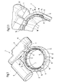
- FIG. 1 is a top perspective view of an integrated throttle body To take flow channels for a temperature control medium.
- a throttle device 1 the housing of which is constructed in several parts, includes, among other things a lower housing half 2. On the lower housing half 2 there is a lower shell 3 molded on, which is closed by an upper shell 4, in which by the lower shell 3 and the upper shell 4 limited cavity drive elements are added. The drive elements are received in a drive housing 5 Actuator driven, operate a not shown in the illustration of FIG. 1 Throttle.
- the throttle valve or the throttle valve shaft is in bearing shells 6 the other half of the housing.
- the lower housing half 2 comprises an inner wall 8, which has the flow cross section a fluid flow through the throttle device 1 limited.
- ribs 9 configured in the form of a rib in the direction of a surrounding the inner wall 8 outer wall 11 of the lower housing half 2.
- Rib-shaped between the individual configured webs 9 cavities 10 are formed, which are used to control the temperature of the Inner wall 8 limiting the flow cross section of a heating medium, such as e.g. tempered Water or tempered air can be flowed through.
- a heating medium such as e.g. tempered Water or tempered air can be flowed through.
- an end face is provided, on which the throttle valve arrangement 37 (not shown here) (see FIG.
- the outer wall 11 on the lower housing half 2 is raised above the inner wall 8 of the lower housing half 2, so that a bearing surface 7 for one in FIG. 1 is not shown sealing and compensating element is formed.
- the outer wall 11 fixes the radial position of a sealing and compensating element, which is formed with a sleeve-shaped section nestles against the inner wall of the lower housing half 2.
- 1.1 shows a partially cut-open representation of the flow channels for a temperature control medium within the lower half of the throttle body.
- the lower shell receiving the drive component lies along a dividing joint 13 3 of the lower half of the housing and the upper shell 4 which can be accommodated thereon on.
- 1.1 are between the inner wall 8 and the outer wall 11 can be removed in an annular manner around cavities 10 extending around inner wall 8, which are each delimited by rib-shaped webs 9.
- the Contact area i.e.
- a second end face 16 is formed on the underside of the lower housing part 2.
- Fig. 2 shows the top view of a throttle device.
- the lower housing half 2 of a throttle device 1 drive components accommodating one above the other in the drawing plane includes lower and upper shells 3, 4.
- a drive housing is molded onto these 5, which on the lower or upper shells 3, 4 opposite Side is closed by a closure element 23.
- the closure element 23 can be e.g. by means of snap closures 24 on the open end face of the drive housing 5 of the Fix lower housing part 2.
- a throttle valve shaft 20 is a first wing 21.1 and a second wing 21.2 assigned to the throttle valve surface 21.
- the throttle valve shaft 20 on the throttle device 1 is the throttle valve shaft 20 on the throttle device 1 and thus those on the throttle valve shaft 20 first wing 21.1 and 21.2 rotated.
- the housing components of the throttle device 1 can, for example, by insert screws 22 can be connected to one another, on which the plan view according to FIG Front is shown.
- 2.1 shows a section through the throttle device according to the section course B-B in Fig. 2.
- FIG. 2.1 shows that the throttle device 1 or its lower housing half 2 a throttle valve arrangement comprising the throttle valve shaft 20 37 can be inserted.
- the throttle valve shaft Comprising 20, e.g. a drive element 35 can be molded directly, which in assembled state of the throttle device 1 from the lower shell 3 of the lower housing part 2 and the upper shell 4 covering this can be connected.
- the throttle valve shaft 20 can in turn be enclosed by storage elements 33, 34, which in the in 1 and Fig. 1.1 bearing shells 6 for the throttle valve shaft 20 and in the lower housing half 2 insertable and fixable by mounting the upper housing half is.
- a positive locking section 32 can be provided for fixing an air connection hose.
- the throttle valve shaft 20 of the throttle valve assembly 37 is from shaft seals 33, 34 for Enclosed ease of movement in the bearing shells 6 of the lower housing half 2.
- a first sealing and compensating element 30 is in the lower housing half 2 of the Throttle device 1 arranged that a contact surface extending in the radial direction 43, which seals the cavities 10 in the lower housing half 2.
- the inner wall 46 of the first sealing and compensating element 30 has no conically running inlet area 45, the widest cross section 42 of which on the throttle valve arrangement 37 is the opposite side and its narrowest cross section 41 the diameter of the Throttle valve shaft 20 corresponds to the throttle valve wing 21.1 or 21.2.
- Sealing and compensating element 30, which is designed as an elastomer molded part, can this can also be obtained from a deformable and hardenable material, the final one Shaping when installing the other half of the housing on the lower half of the housing 2 is done.
- Designed with either a hardenable and deformable material or as a separate sealing and insert element designed as an elastomer molded part 30 can be made of die-cast aluminum throttle body components Manufacturing inaccuracies occurring in the area of the contact surfaces compensate without rework, since the compensation of the manufacturing inaccuracies by the radially extending contact surface facing the throttle valve arrangement 37 43 is effected.
- Throttle device 1 can be a corresponding to the first sealing and compensating element 30 additional sealing and compensating element 31 may be inserted.
- the two sealing and Compensating elements 30, 31, in the sectional view of FIG. 2.1 on the shaft seals 33 or 34 of the throttle valve shafts 20 rest against the lower housing half 2 and the further housing half along their end faces, not shown in FIG. 2.1 from.
- Also on the further sealing and compensating element 31 is due to the contour Inner wall 46 extending from the widest cross section 42, a conical inlet funnel 45 trained.
- a drive housing 5 is formed on the lower housing half 2, into which a drive shown here as a solid material is included in a sectional view.
- the drive acts on the drive components enclosed by the lower shell 3 and upper shell 4 35 a, the throttle valve shaft 20 of the throttle valve assembly 37 within of the flow cross section that is passed by the fluid flow.
- the throttle valve assembly 37 which offsets the throttle valve shaft 20 and on it first wing 21.1 which is accommodated exactly opposite one another or opposite one another and comprises the second wing 21.2, can be obtained, for example, as an insert component 37 be what butt joints 38 with the also in the flow cross section of the Fluid flow fitted first sealing and compensating element 30 and the other Form sealing and compensating element 31.
- an insert component 37 be what butt joints 38 with the also in the flow cross section of the Fluid flow fitted first sealing and compensating element 30 and the other Form sealing and compensating element 31.
- shoulders 36 are formed in the area of the narrowest cross section his. A formation of shoulders 36 on the procured as insert 37 Throttle valve arrangement is not absolutely necessary.
- the narrowest cross section which on the first or the further sealing and compensating element 30, 31 the flow cross-section can flow through the fluid channel of the throttle device 1 different throttle valve diameters can be adjusted.
- the invention allows Solution the installation of different sized throttle valve assemblies 37 in one and the same housing, the ones shown in FIG. 2.2 in a sectional view Sealing and compensating elements 30 and 31 as reducing elements of the flow cross section serve.
- the sealing and Compensating elements 30, 31 as shown in Fig. 2.1 from a temperature control medium flowed through cavities 10 in a housing half 2 formed cavities 10 close;
- the contact surface that extends in the radial direction serves 43 as a compensation surface to compensate for manufacturing inaccuracies in the aluminum die casting process manufactured throttle body components.
- the components acting as sealing and compensating elements 30 and 31 in FIG. 2.2 can in addition to their design as separate elastomer insert rings also made of curable, formable materials exist, their final shape when mounting the housing halves the throttle device 1 and the insert module in the assembled state 37 of the throttle valve element and fix the parting line against the housing half Seal external air inlet from the outside.
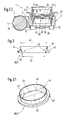
- Fig. 3 shows the section through a sealing and compensating element.
- FIG. 3 shows that this is a separate, flexible elastomer material manufactured insert 30 and 31 a narrowest cross section 41 and one widest cross section 42. Due to the cross-sectional difference, an inlet funnel, i.e. a conical frusto-conical inlet area 45 is formed, which is the narrowest Cross section 41 is provided with an angled outlet 40. In the direction of flow of the fluid flow passing through the throttle device 1 is seen at passage of the narrowest cross section 41 through the angled outlet 40 arranged there a homogeneous Flow profile imprinted. The reproduced in Fig.
- Sealing and compensating element 30 and 31 comprises a extending in the radial direction Contact surface 43 and a molded onto it, with a constant diameter trained sleeve-shaped section 44. With the sleeve-shaped section 44 lies the sealing and compensating element 30 and 31 on the inner wall 8 of the throttle device 1 on.
- One side that closes in the radial direction extending contact surface 43 (see illustration according to FIG. 2.1) cavities 10 for temperature control of the housing of the throttle device 1 while the other side of the radially extending contact surface 43 a compensation function with regard to manufacturing inaccuracies on the balances with the lower housing half 2 to be joined further housing half without the Machining rework on housing components manufactured using the aluminum die casting process required are.
- FIG. 3.1 is a top perspective view of the sealing and compensating element according to FIG the sectional views in Fig. 3 can be seen.
- the inner wall 46 Depending on the diameter difference of the narrowest Cross-section 41 or the widest cross-section 42 arises on the inner wall 46 a conical inlet funnel with respect to the narrowest cross section 41 of the sealing and Compensating element 30 or 31.
- the inner wall 46 essentially runs smooth, so that the narrowest cross-section 41 of the sealing and compensating element 30 or 31 emerging fluid flow through the angled outlet 40 over the cross section homogeneous flow profile can be impressed, in which eddies and dead water areas are avoided.
- Cross-section 41 By choosing the closest Cross-section 41 can be the proposed one, both as a discrete elastomer molded part as well as sealing and compensating element made of curable, deformable material 30 or 31 can also be used as a reducer, so that in one example a component serving as a standard housing type of a throttle device 1 Throttle valve assembly 37 can be installed, the throttle valve surface diameter is less than the free flow cross section.
- Throttle valve assembly 37 can be installed, the throttle valve surface diameter is less than the free flow cross section.
- the first and the Another sealing and compensating element 30, 31 formed inlet funnel 45 can the flow in the area of the narrowest cross-section, i.e. where the insert 37 procured throttle valve device in the free flow cross section of the throttle device 1 is arranged to accelerate.
Landscapes
- Engineering & Computer Science (AREA)
- Chemical & Material Sciences (AREA)
- Combustion & Propulsion (AREA)
- Mechanical Engineering (AREA)
- General Engineering & Computer Science (AREA)
- Control Of Throttle Valves Provided In The Intake System Or In The Exhaust System (AREA)
Applications Claiming Priority (2)
| Application Number | Priority Date | Filing Date | Title |
|---|---|---|---|
| DE10138931 | 2001-08-08 | ||
| DE10138931A DE10138931A1 (de) | 2001-08-08 | 2001-08-08 | Drosselvorrichtungsgehäuse mit flexiblen Ausgleichselementen für Brennkraftmaschinen |
Publications (3)
| Publication Number | Publication Date |
|---|---|
| EP1283340A2 true EP1283340A2 (fr) | 2003-02-12 |
| EP1283340A3 EP1283340A3 (fr) | 2003-12-10 |
| EP1283340B1 EP1283340B1 (fr) | 2005-05-04 |
Family
ID=7694793
Family Applications (1)
| Application Number | Title | Priority Date | Filing Date |
|---|---|---|---|
| EP02015314A Expired - Lifetime EP1283340B1 (fr) | 2001-08-08 | 2002-07-10 | Boitier de dispositif d'étranglement avec éléments de compensation pour moteurs à combustion interne |
Country Status (4)
| Country | Link |
|---|---|
| US (1) | US6761348B2 (fr) |
| EP (1) | EP1283340B1 (fr) |
| JP (1) | JP2003056373A (fr) |
| DE (2) | DE10138931A1 (fr) |
Cited By (1)
| Publication number | Priority date | Publication date | Assignee | Title |
|---|---|---|---|---|
| EP1832512A3 (fr) * | 2006-03-06 | 2009-03-04 | Honeywell International Inc. | Vanne d'échappement à papillon de circuit de régulation de pression de cabine compacte, légère avec des caractéristiques de redondance |
Families Citing this family (21)
| Publication number | Priority date | Publication date | Assignee | Title |
|---|---|---|---|---|
| EP1167724B1 (fr) * | 1999-03-29 | 2004-05-26 | Hitachi, Ltd. | Dispositif d'etranglement commande de maniere electronique |
| DE10147333A1 (de) * | 2001-09-26 | 2003-04-24 | Bosch Gmbh Robert | Variantenreduzierte Drosseleinrichtung mit austauschbaren Gehäuseteilen |
| DE10156213A1 (de) * | 2001-11-15 | 2003-06-05 | Siemens Ag | Drosselklappenstutzen |
| DE10254616A1 (de) * | 2002-11-22 | 2004-06-17 | Siemens Ag | Verfarhen zur Herstellung eines Drosselklappenstutzens |
| US20090291112A1 (en) * | 2003-05-16 | 2009-11-26 | Truncale Katherine G | Allograft osteochondral plug combined with cartilage particle mixture |
| US7004138B2 (en) * | 2003-07-15 | 2006-02-28 | Eaton Corporation | Pressure pulse communication in an engine intake manifold |
| EP1498596B1 (fr) * | 2003-07-17 | 2006-10-18 | Arno Hofmann | Joint d'étanchéité à fente étrangleur pour soupapes |
| JP4376017B2 (ja) * | 2003-08-01 | 2009-12-02 | 株式会社デンソー | 電子制御式スロットル制御装置 |
| JP2006017080A (ja) * | 2004-07-05 | 2006-01-19 | Denso Corp | 内燃機関用吸気制御装置 |
| US7571742B2 (en) * | 2005-03-23 | 2009-08-11 | Honeywell International Inc. | Butterfly outflow valve |
| KR100666136B1 (ko) * | 2006-03-08 | 2007-01-09 | 백완기 | 가변 풍량 조절장치 |
| JP4551351B2 (ja) * | 2006-04-18 | 2010-09-29 | 株式会社デンソー | スロットル弁装置 |
| JP4739128B2 (ja) * | 2006-06-28 | 2011-08-03 | 愛三工業株式会社 | 吸気制御弁 |
| JP2008063959A (ja) * | 2006-09-05 | 2008-03-21 | Aisan Ind Co Ltd | スロットル装置 |
| US8091862B2 (en) * | 2006-09-29 | 2012-01-10 | Sikorsky Aircraft Corporation | Butterfly valves having sleeve inserts |
| US10488074B2 (en) | 2011-09-09 | 2019-11-26 | Capital Hardware Supply, Inc. | Airtight bushing for ductwork damper and the like and ductwork damper unit incorporating same |
| DE102012211631A1 (de) | 2012-07-04 | 2014-01-09 | Robert Bosch Gmbh | Drosselvorrichtung mit zusätzlichen Wellenlagerabdichtungen |
| ITBO20130676A1 (it) * | 2013-12-04 | 2015-06-05 | Magneti Marelli Spa | Valvola a farfalla per un motore a combustione interna provvista di una sede valvola metallica costampata all'interno di un corpo valvola in materiale plastico |
| JP6354577B2 (ja) * | 2014-12-25 | 2018-07-11 | 株式会社デンソー | バルブ装置 |
| CN205225467U (zh) * | 2015-11-19 | 2016-05-11 | 大陆汽车电子(芜湖)有限公司 | 一种电子节气门 |
| IT202100004703A1 (it) * | 2021-03-01 | 2022-09-01 | Marelli Europe Spa | Valvola a farfalla motorizzata per un condotto di scarico |
Citations (4)
| Publication number | Priority date | Publication date | Assignee | Title |
|---|---|---|---|---|
| DE2949041B1 (de) | 1979-12-06 | 1981-06-04 | Bosch und Pierburg System oHG, 4040 Neuss | Heizung zur Gemischaufbereitung bei Gemischbildnern |
| DE3346167A1 (de) | 1983-12-21 | 1985-07-04 | Vdo Adolf Schindling Ag, 6000 Frankfurt | Drosselklappenstutzen |
| DE19843771A1 (de) | 1998-09-24 | 2000-03-30 | Mannesmann Vdo Ag | Elektromotorisches Stellglied, insbesondere mit einer Drosselklappe |
| DE10114221A1 (de) | 2001-03-23 | 2002-10-02 | Bosch Gmbh Robert | Beheizbare Drosselvorrichtung für Brennkraftmaschinen |
Family Cites Families (22)
| Publication number | Priority date | Publication date | Assignee | Title |
|---|---|---|---|---|
| US1083317A (en) * | 1913-04-19 | 1914-01-06 | Internat Nitrogen And Power Company Ltd | Treatment of peat and the like. |
| US2643966A (en) * | 1925-01-16 | 1953-06-30 | Us Sec War | Vesicant composition for and method of rendering water hazardous |
| US2949041A (en) * | 1957-04-24 | 1960-08-16 | Wildhaber Ernest | Angular gear drive |
| US3986699A (en) * | 1974-07-02 | 1976-10-19 | Posi-Seal International, Inc. | Positive shut-off seal |
| FR2326235A1 (fr) * | 1975-10-01 | 1977-04-29 | Renault | Buse elastique a debit variable |
| US4202437A (en) * | 1977-10-06 | 1980-05-13 | Gordon James R | Scraper assembly for a conveyor belt |
| US4348006A (en) * | 1979-07-19 | 1982-09-07 | Kerotest Manufacturing Corp. | Plastic valve assembly |
| US4329522A (en) * | 1980-10-14 | 1982-05-11 | The United States Of America As Represented By The Secretary Of The Army | 1,3,5,7-Tetranitroadamantane and process for preparing same |
| US4401690A (en) * | 1982-02-01 | 1983-08-30 | Ppg Industries, Inc. | Thermochromic vanadium oxide with depressed switching temperature |
| JP2612099B2 (ja) * | 1991-01-29 | 1997-05-21 | 株式会社日立製作所 | 絞り弁組立体 |
| DE4310901C2 (de) * | 1993-04-02 | 1995-10-12 | Mtu Friedrichshafen Gmbh | Klappenabsperrventil |
| AT410245B (de) | 1993-07-14 | 2003-03-25 | Bosch Gmbh Robert | Aus kunststoff bestehender formkörper |
| DE4329522A1 (de) | 1993-09-02 | 1995-03-09 | Mann & Hummel Filter | Drosseleinrichtung |
| DE4401690A1 (de) | 1994-01-21 | 1995-07-27 | Bosch Gmbh Robert | Saugrohr |
| DE19525510B4 (de) | 1995-07-13 | 2008-05-08 | Robert Bosch Gmbh | Drosselklappenstelleinheit |
| US5876015A (en) * | 1995-08-03 | 1999-03-02 | Schaeffer; J. Michael | Butterfly damper |
| US6451238B1 (en) | 1998-04-07 | 2002-09-17 | Honda Giken Kogyo Kabushiki Kaisha | Process for producing intake member of resin, and intake member of resin |
| JP2000297661A (ja) * | 1999-04-14 | 2000-10-24 | Aisan Ind Co Ltd | 内燃機関の吸気装置 |
| DE19936457A1 (de) * | 1999-08-03 | 2001-02-08 | Mann & Hummel Filter | Drosseleinrichtung mit einer Klappe zum Einbau in eine Flanschverbindung |
| EP1083317A3 (fr) * | 1999-09-08 | 2001-09-05 | Siemens Canada limited | Elément de corps de papillon pour collecteur d'admission |
| US6354267B1 (en) | 2000-03-28 | 2002-03-12 | Borgwarner Inc. | Injection molded throttle body |
| JP2002297661A (ja) | 2001-03-30 | 2002-10-11 | Tokyo Electric Power Co Inc:The | Web検索装置 |
-
2001
- 2001-08-08 DE DE10138931A patent/DE10138931A1/de not_active Ceased
-
2002
- 2002-07-10 DE DE50202977T patent/DE50202977D1/de not_active Expired - Lifetime
- 2002-07-10 EP EP02015314A patent/EP1283340B1/fr not_active Expired - Lifetime
- 2002-08-05 JP JP2002227566A patent/JP2003056373A/ja active Pending
- 2002-08-08 US US10/214,159 patent/US6761348B2/en not_active Expired - Fee Related
Patent Citations (4)
| Publication number | Priority date | Publication date | Assignee | Title |
|---|---|---|---|---|
| DE2949041B1 (de) | 1979-12-06 | 1981-06-04 | Bosch und Pierburg System oHG, 4040 Neuss | Heizung zur Gemischaufbereitung bei Gemischbildnern |
| DE3346167A1 (de) | 1983-12-21 | 1985-07-04 | Vdo Adolf Schindling Ag, 6000 Frankfurt | Drosselklappenstutzen |
| DE19843771A1 (de) | 1998-09-24 | 2000-03-30 | Mannesmann Vdo Ag | Elektromotorisches Stellglied, insbesondere mit einer Drosselklappe |
| DE10114221A1 (de) | 2001-03-23 | 2002-10-02 | Bosch Gmbh Robert | Beheizbare Drosselvorrichtung für Brennkraftmaschinen |
Cited By (1)
| Publication number | Priority date | Publication date | Assignee | Title |
|---|---|---|---|---|
| EP1832512A3 (fr) * | 2006-03-06 | 2009-03-04 | Honeywell International Inc. | Vanne d'échappement à papillon de circuit de régulation de pression de cabine compacte, légère avec des caractéristiques de redondance |
Also Published As
| Publication number | Publication date |
|---|---|
| JP2003056373A (ja) | 2003-02-26 |
| DE50202977D1 (de) | 2005-06-09 |
| US20030030022A1 (en) | 2003-02-13 |
| EP1283340A3 (fr) | 2003-12-10 |
| DE10138931A1 (de) | 2003-03-06 |
| US6761348B2 (en) | 2004-07-13 |
| EP1283340B1 (fr) | 2005-05-04 |
Similar Documents
| Publication | Publication Date | Title |
|---|---|---|
| EP1283340B1 (fr) | Boitier de dispositif d'étranglement avec éléments de compensation pour moteurs à combustion interne | |
| DE112005001222B4 (de) | Verfahren zur Herstellung eines Drosselkörpers und Drosselkörper | |
| EP0717815B1 (fr) | Dispositif d'etranglement | |
| EP1243774B1 (fr) | Dispositif d'étranglement chauffant pour moteurs à combustion interne | |
| DE69012150T2 (de) | Wellenprallplatte aus einem stück für das einlasssystem einer brennkraftmaschine. | |
| EP1200718B1 (fr) | Ensemble collecteur d'admission | |
| DE60029598T2 (de) | Einrichtung zur Durchflusssteuerung in einem Leitungsabschnitt oder einem Durchgang und Ansaugvorrichtung mit einer solchen Einrichtung | |
| WO2000065214A1 (fr) | Ensemble volets de commande constitue de volets de commande, moules par injection au moment du montage, ou de modules a volets | |
| DE102004056764B4 (de) | Drosselkörper und Verfahren zum Herstellen solcher Drosselkörper | |
| EP1591641A2 (fr) | Ensemble de vanne dans le système d'admission d'un moteur | |
| EP0726388A1 (fr) | Dispositif d'admission | |
| DE10105526B4 (de) | Verfahren zur Herstellung einer Klappenanordnung | |
| EP1200721B1 (fr) | Soupape | |
| DE102009025341A1 (de) | Regelventil | |
| WO2021250176A1 (fr) | Distributeur et cage pour un distributeur | |
| EP1298299A2 (fr) | Dispositif d'étranglement avec des éléments de boítiers échangeables | |
| EP1281849A2 (fr) | Dispositif d'étranglement avec un réceptacle et des contacts électriques pour l'unité motrice | |
| EP1200722B1 (fr) | Dispositif d'etranglement a volet destine au montage dans une jonction a brides | |
| DE10235997A1 (de) | Medienmassen-Steuerelement und Ansaugvorrichtung für Verbrennungsmotoren | |
| WO1995006809A1 (fr) | Dispositif d'etranglement | |
| EP4311961A1 (fr) | Robinet à tournant sphérique | |
| EP1355057B1 (fr) | Dispositif pour la recirculation des gaz d'échappement d'un moteur à combustion interne | |
| EP1350020B1 (fr) | Soupape a clapet | |
| DE19813024A1 (de) | Hubkolbenmotor mit geteilter Zylinderkopfhaube | |
| EP1559937A1 (fr) | Tiroir de soupape pour une vanne à voies multiples |
Legal Events
| Date | Code | Title | Description |
|---|---|---|---|
| PUAI | Public reference made under article 153(3) epc to a published international application that has entered the european phase |
Free format text: ORIGINAL CODE: 0009012 |
|
| AK | Designated contracting states |
Designated state(s): AT BE BG CH CY CZ DE DK EE ES FI FR GB GR IE IT LI LU MC NL PT SE SK TR |
|
| AX | Request for extension of the european patent |
Extension state: AL LT LV MK RO SI |
|
| PUAL | Search report despatched |
Free format text: ORIGINAL CODE: 0009013 |
|
| AK | Designated contracting states |
Kind code of ref document: A3 Designated state(s): AT BE BG CH CY CZ DE DK EE ES FI FR GB GR IE IT LI LU MC NL PT SE SK TR |
|
| AX | Request for extension of the european patent |
Extension state: AL LT LV MK RO SI |
|
| 17P | Request for examination filed |
Effective date: 20040611 |
|
| AKX | Designation fees paid |
Designated state(s): DE FR IT |
|
| GRAP | Despatch of communication of intention to grant a patent |
Free format text: ORIGINAL CODE: EPIDOSNIGR1 |
|
| GRAS | Grant fee paid |
Free format text: ORIGINAL CODE: EPIDOSNIGR3 |
|
| GRAA | (expected) grant |
Free format text: ORIGINAL CODE: 0009210 |
|
| AK | Designated contracting states |
Kind code of ref document: B1 Designated state(s): DE FR IT |
|
| REG | Reference to a national code |
Ref country code: IE Ref legal event code: FG4D Free format text: LANGUAGE OF EP DOCUMENT: GERMAN |
|
| REF | Corresponds to: |
Ref document number: 50202977 Country of ref document: DE Date of ref document: 20050609 Kind code of ref document: P |
|
| PLBE | No opposition filed within time limit |
Free format text: ORIGINAL CODE: 0009261 |
|
| STAA | Information on the status of an ep patent application or granted ep patent |
Free format text: STATUS: NO OPPOSITION FILED WITHIN TIME LIMIT |
|
| 26N | No opposition filed |
Effective date: 20060207 |
|
| EN | Fr: translation not filed | ||
| PG25 | Lapsed in a contracting state [announced via postgrant information from national office to epo] |
Ref country code: FR Free format text: LAPSE BECAUSE OF NON-PAYMENT OF DUE FEES Effective date: 20050731 |
|
| PG25 | Lapsed in a contracting state [announced via postgrant information from national office to epo] |
Ref country code: FR Free format text: LAPSE BECAUSE OF NON-PAYMENT OF DUE FEES Effective date: 20050504 |
|
| PGFP | Annual fee paid to national office [announced via postgrant information from national office to epo] |
Ref country code: IT Payment date: 20130729 Year of fee payment: 12 |
|
| PGFP | Annual fee paid to national office [announced via postgrant information from national office to epo] |
Ref country code: DE Payment date: 20140925 Year of fee payment: 13 |
|
| PG25 | Lapsed in a contracting state [announced via postgrant information from national office to epo] |
Ref country code: IT Free format text: LAPSE BECAUSE OF NON-PAYMENT OF DUE FEES Effective date: 20140710 |
|
| REG | Reference to a national code |
Ref country code: DE Ref legal event code: R119 Ref document number: 50202977 Country of ref document: DE |
|
| PG25 | Lapsed in a contracting state [announced via postgrant information from national office to epo] |
Ref country code: DE Free format text: LAPSE BECAUSE OF NON-PAYMENT OF DUE FEES Effective date: 20160202 |