EP1283340A2 - Throttle apparatus housing with flexible compensating elements for internal combustion engines - Google Patents
Throttle apparatus housing with flexible compensating elements for internal combustion engines Download PDFInfo
- Publication number
- EP1283340A2 EP1283340A2 EP02015314A EP02015314A EP1283340A2 EP 1283340 A2 EP1283340 A2 EP 1283340A2 EP 02015314 A EP02015314 A EP 02015314A EP 02015314 A EP02015314 A EP 02015314A EP 1283340 A2 EP1283340 A2 EP 1283340A2
- Authority
- EP
- European Patent Office
- Prior art keywords
- sealing
- housing
- throttle device
- section
- compensating element
- Prior art date
- Legal status (The legal status is an assumption and is not a legal conclusion. Google has not performed a legal analysis and makes no representation as to the accuracy of the status listed.)
- Granted
Links
Images

Classifications
-
- F—MECHANICAL ENGINEERING; LIGHTING; HEATING; WEAPONS; BLASTING
- F02—COMBUSTION ENGINES; HOT-GAS OR COMBUSTION-PRODUCT ENGINE PLANTS
- F02D—CONTROLLING COMBUSTION ENGINES
- F02D9/00—Controlling engines by throttling air or fuel-and-air induction conduits or exhaust conduits
- F02D9/08—Throttle valves specially adapted therefor; Arrangements of such valves in conduits
- F02D9/10—Throttle valves specially adapted therefor; Arrangements of such valves in conduits having pivotally-mounted flaps
- F02D9/1035—Details of the valve housing
- F02D9/106—Sealing of the valve shaft in the housing, e.g. details of the bearings
-
- F—MECHANICAL ENGINEERING; LIGHTING; HEATING; WEAPONS; BLASTING
- F02—COMBUSTION ENGINES; HOT-GAS OR COMBUSTION-PRODUCT ENGINE PLANTS
- F02D—CONTROLLING COMBUSTION ENGINES
- F02D9/00—Controlling engines by throttling air or fuel-and-air induction conduits or exhaust conduits
- F02D9/08—Throttle valves specially adapted therefor; Arrangements of such valves in conduits
- F02D9/10—Throttle valves specially adapted therefor; Arrangements of such valves in conduits having pivotally-mounted flaps
- F02D9/1035—Details of the valve housing
- F02D9/104—Shaping of the flow path in the vicinity of the flap, e.g. having inserts in the housing
-
- F—MECHANICAL ENGINEERING; LIGHTING; HEATING; WEAPONS; BLASTING
- F05—INDEXING SCHEMES RELATING TO ENGINES OR PUMPS IN VARIOUS SUBCLASSES OF CLASSES F01-F04
- F05C—INDEXING SCHEME RELATING TO MATERIALS, MATERIAL PROPERTIES OR MATERIAL CHARACTERISTICS FOR MACHINES, ENGINES OR PUMPS OTHER THAN NON-POSITIVE-DISPLACEMENT MACHINES OR ENGINES
- F05C2201/00—Metals
- F05C2201/02—Light metals
- F05C2201/021—Aluminium
Definitions
- a throttle device In internal combustion engines used in vehicles, a throttle device is used today, which is generally designed as a circular flap, is accommodated in the intake tract of the internal combustion engine and doses the volume flow of fresh air that is to be sucked in for combustion. Due to the high flow velocities of the residual air flow in the intake tract and at low outside temperatures, the H 2 O contained in the fresh air can condense on the wall of the pipe; if it cools further, ice can form inside the fresh air line, which can significantly impair the smooth operation of a throttle valve. Furthermore, in the case of split throttle plate housings, care must be taken to ensure that no extraneous air can enter the intake tract behind the throttle valve on the side facing the internal combustion engine in the region of the dividing joints of the housing halves.
- DE 33 46 167 Al relates to a throttle valve assembly.
- a throttle valve is arranged on a shaft which in turn can be fixed on both sides in the socket housing using plain bearings.
- This plain bearing are each pressed into a shaft bore and have a throttle valve side End faces that are curved according to the wall of the housing bore and form part of this wall.
- the leakage rate is due to this design of the plain bearing this throttle body according to DE 33 46 167 A1 extremely low.
- DE 198 43 771 A1 relates to an electromotive actuator, in particular with a throttle valve.
- An electromotive actuator with a housing is disclosed and an electric motor arranged on a drive side within the housing for driving a movable element arranged in the housing.
- this movable element is in particular a throttle valve, provided is that on the housing a separate electronics housing for receiving a control and / or Evaluation electronics can be attached.
- this allows in particular Avoid electromagnetic interference and on the other hand can be standard Manufactured and no control device required electronic actuators continue to be used are required without changes to the shape for the manufacture of the actuator are.
- a heater for mixture preparation in mixture formers is known. According to this solution, it is a heater for mixture preparation Internal combustion engine mixture formers with a pipe wall delimiting a main flow and with a main throttle element downstream and a fuel metering device in the upstream part of a mixing chamber. This is over part of this Longitudinal extension as a double wall heat exchanger with an annular Heating water room formed, at one end a water inlet pipe and on has a water drainage nozzle at its other end.
- the heat exchanger is over one thermally controlled connection valve with a valve that opens from higher temperatures Cooling water circuit connectable. It is located when the connecting valve is blocked and at switched off cooling water circuit above the cooling water level.
- the Andes Main flow path of the mixture generator adjacent inner wall of the heat exchanger consists of an electrical heating resistor material and is dependent on one thermally controlled from the cooling water temperature, from a certain higher water temperature opening electrical switching element electrically connected to a voltage source.
- the advantages of the solution proposed according to the invention can be seen above all in that now with a single insert element between the housing halves Throttle housing, which is composed of an upper shell and a lower shell, both a seal of the housing element against external air intake is given during on the other hand, the insertion element compensates for tolerances on the division joint of the two housing halves, which is configured, for example, as an aluminum injection molded component Throttle body. This allows reworking operations that are carried out in the Usually be made by machining, when joining the housing halves avoid the throttle body. With the in the dividing line of the two Half of the integrated insert can also be inserted in the throttle body Seal the integrated heater.
- the insert element can effectively seal them.
- the insert element can have differences in diameter in the flow cross section equalize the throttle body halves so that there are no jumps in diameter occur and consequently no dead water areas arise in which there is in the intake air Accumulate contained media over the operating time of the internal combustion engine.
- the insert element can be designed as a prefabricated molded part with a tapered inner wall; on the other hand, it can also be hardened Form material so that the two throttle body halves after assembly are fixed for later use.
- Both the design of the sealing element as a prefabricated preformed elastomer ring as well as the design of the sealing element made of a formable material that hardens after processing allows compensation of manufacturing inaccuracies on the end faces of the upper one to be joined or lower throttle body halves. Compensation for manufacturing inaccuracies i.e., e.g. Out-of-roundness and runout were so far mostly due to one on the machining path, complex and expensive post-processing of each other throttle valve halves to be joined possible.
- sealing element which is procured as an elastomer insert ring or as a hardening molding compound can by appropriate shaping of the flow cross section facing Wall of the sealing element, in particular over a molded angled Outlet, in the flow direction a better flow guidance of the intake air flow in of the suction line in the intake tract of an internal combustion engine.
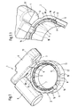
- FIG. 1 is a top perspective view of an integrated throttle body To take flow channels for a temperature control medium.
- a throttle device 1 the housing of which is constructed in several parts, includes, among other things a lower housing half 2. On the lower housing half 2 there is a lower shell 3 molded on, which is closed by an upper shell 4, in which by the lower shell 3 and the upper shell 4 limited cavity drive elements are added. The drive elements are received in a drive housing 5 Actuator driven, operate a not shown in the illustration of FIG. 1 Throttle.
- the throttle valve or the throttle valve shaft is in bearing shells 6 the other half of the housing.
- the lower housing half 2 comprises an inner wall 8, which has the flow cross section a fluid flow through the throttle device 1 limited.
- ribs 9 configured in the form of a rib in the direction of a surrounding the inner wall 8 outer wall 11 of the lower housing half 2.
- Rib-shaped between the individual configured webs 9 cavities 10 are formed, which are used to control the temperature of the Inner wall 8 limiting the flow cross section of a heating medium, such as e.g. tempered Water or tempered air can be flowed through.
- a heating medium such as e.g. tempered Water or tempered air can be flowed through.
- an end face is provided, on which the throttle valve arrangement 37 (not shown here) (see FIG.
- the outer wall 11 on the lower housing half 2 is raised above the inner wall 8 of the lower housing half 2, so that a bearing surface 7 for one in FIG. 1 is not shown sealing and compensating element is formed.
- the outer wall 11 fixes the radial position of a sealing and compensating element, which is formed with a sleeve-shaped section nestles against the inner wall of the lower housing half 2.
- 1.1 shows a partially cut-open representation of the flow channels for a temperature control medium within the lower half of the throttle body.
- the lower shell receiving the drive component lies along a dividing joint 13 3 of the lower half of the housing and the upper shell 4 which can be accommodated thereon on.
- 1.1 are between the inner wall 8 and the outer wall 11 can be removed in an annular manner around cavities 10 extending around inner wall 8, which are each delimited by rib-shaped webs 9.
- the Contact area i.e.
- a second end face 16 is formed on the underside of the lower housing part 2.
- Fig. 2 shows the top view of a throttle device.
- the lower housing half 2 of a throttle device 1 drive components accommodating one above the other in the drawing plane includes lower and upper shells 3, 4.
- a drive housing is molded onto these 5, which on the lower or upper shells 3, 4 opposite Side is closed by a closure element 23.
- the closure element 23 can be e.g. by means of snap closures 24 on the open end face of the drive housing 5 of the Fix lower housing part 2.
- a throttle valve shaft 20 is a first wing 21.1 and a second wing 21.2 assigned to the throttle valve surface 21.
- the throttle valve shaft 20 on the throttle device 1 is the throttle valve shaft 20 on the throttle device 1 and thus those on the throttle valve shaft 20 first wing 21.1 and 21.2 rotated.
- the housing components of the throttle device 1 can, for example, by insert screws 22 can be connected to one another, on which the plan view according to FIG Front is shown.
- 2.1 shows a section through the throttle device according to the section course B-B in Fig. 2.
- FIG. 2.1 shows that the throttle device 1 or its lower housing half 2 a throttle valve arrangement comprising the throttle valve shaft 20 37 can be inserted.
- the throttle valve shaft Comprising 20, e.g. a drive element 35 can be molded directly, which in assembled state of the throttle device 1 from the lower shell 3 of the lower housing part 2 and the upper shell 4 covering this can be connected.
- the throttle valve shaft 20 can in turn be enclosed by storage elements 33, 34, which in the in 1 and Fig. 1.1 bearing shells 6 for the throttle valve shaft 20 and in the lower housing half 2 insertable and fixable by mounting the upper housing half is.
- a positive locking section 32 can be provided for fixing an air connection hose.
- the throttle valve shaft 20 of the throttle valve assembly 37 is from shaft seals 33, 34 for Enclosed ease of movement in the bearing shells 6 of the lower housing half 2.
- a first sealing and compensating element 30 is in the lower housing half 2 of the Throttle device 1 arranged that a contact surface extending in the radial direction 43, which seals the cavities 10 in the lower housing half 2.
- the inner wall 46 of the first sealing and compensating element 30 has no conically running inlet area 45, the widest cross section 42 of which on the throttle valve arrangement 37 is the opposite side and its narrowest cross section 41 the diameter of the Throttle valve shaft 20 corresponds to the throttle valve wing 21.1 or 21.2.
- Sealing and compensating element 30, which is designed as an elastomer molded part, can this can also be obtained from a deformable and hardenable material, the final one Shaping when installing the other half of the housing on the lower half of the housing 2 is done.
- Designed with either a hardenable and deformable material or as a separate sealing and insert element designed as an elastomer molded part 30 can be made of die-cast aluminum throttle body components Manufacturing inaccuracies occurring in the area of the contact surfaces compensate without rework, since the compensation of the manufacturing inaccuracies by the radially extending contact surface facing the throttle valve arrangement 37 43 is effected.
- Throttle device 1 can be a corresponding to the first sealing and compensating element 30 additional sealing and compensating element 31 may be inserted.
- the two sealing and Compensating elements 30, 31, in the sectional view of FIG. 2.1 on the shaft seals 33 or 34 of the throttle valve shafts 20 rest against the lower housing half 2 and the further housing half along their end faces, not shown in FIG. 2.1 from.
- Also on the further sealing and compensating element 31 is due to the contour Inner wall 46 extending from the widest cross section 42, a conical inlet funnel 45 trained.
- a drive housing 5 is formed on the lower housing half 2, into which a drive shown here as a solid material is included in a sectional view.
- the drive acts on the drive components enclosed by the lower shell 3 and upper shell 4 35 a, the throttle valve shaft 20 of the throttle valve assembly 37 within of the flow cross section that is passed by the fluid flow.
- the throttle valve assembly 37 which offsets the throttle valve shaft 20 and on it first wing 21.1 which is accommodated exactly opposite one another or opposite one another and comprises the second wing 21.2, can be obtained, for example, as an insert component 37 be what butt joints 38 with the also in the flow cross section of the Fluid flow fitted first sealing and compensating element 30 and the other Form sealing and compensating element 31.
- an insert component 37 be what butt joints 38 with the also in the flow cross section of the Fluid flow fitted first sealing and compensating element 30 and the other Form sealing and compensating element 31.
- shoulders 36 are formed in the area of the narrowest cross section his. A formation of shoulders 36 on the procured as insert 37 Throttle valve arrangement is not absolutely necessary.
- the narrowest cross section which on the first or the further sealing and compensating element 30, 31 the flow cross-section can flow through the fluid channel of the throttle device 1 different throttle valve diameters can be adjusted.
- the invention allows Solution the installation of different sized throttle valve assemblies 37 in one and the same housing, the ones shown in FIG. 2.2 in a sectional view Sealing and compensating elements 30 and 31 as reducing elements of the flow cross section serve.
- the sealing and Compensating elements 30, 31 as shown in Fig. 2.1 from a temperature control medium flowed through cavities 10 in a housing half 2 formed cavities 10 close;
- the contact surface that extends in the radial direction serves 43 as a compensation surface to compensate for manufacturing inaccuracies in the aluminum die casting process manufactured throttle body components.
- the components acting as sealing and compensating elements 30 and 31 in FIG. 2.2 can in addition to their design as separate elastomer insert rings also made of curable, formable materials exist, their final shape when mounting the housing halves the throttle device 1 and the insert module in the assembled state 37 of the throttle valve element and fix the parting line against the housing half Seal external air inlet from the outside.
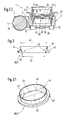
- Fig. 3 shows the section through a sealing and compensating element.
- FIG. 3 shows that this is a separate, flexible elastomer material manufactured insert 30 and 31 a narrowest cross section 41 and one widest cross section 42. Due to the cross-sectional difference, an inlet funnel, i.e. a conical frusto-conical inlet area 45 is formed, which is the narrowest Cross section 41 is provided with an angled outlet 40. In the direction of flow of the fluid flow passing through the throttle device 1 is seen at passage of the narrowest cross section 41 through the angled outlet 40 arranged there a homogeneous Flow profile imprinted. The reproduced in Fig.
- Sealing and compensating element 30 and 31 comprises a extending in the radial direction Contact surface 43 and a molded onto it, with a constant diameter trained sleeve-shaped section 44. With the sleeve-shaped section 44 lies the sealing and compensating element 30 and 31 on the inner wall 8 of the throttle device 1 on.
- One side that closes in the radial direction extending contact surface 43 (see illustration according to FIG. 2.1) cavities 10 for temperature control of the housing of the throttle device 1 while the other side of the radially extending contact surface 43 a compensation function with regard to manufacturing inaccuracies on the balances with the lower housing half 2 to be joined further housing half without the Machining rework on housing components manufactured using the aluminum die casting process required are.
- FIG. 3.1 is a top perspective view of the sealing and compensating element according to FIG the sectional views in Fig. 3 can be seen.
- the inner wall 46 Depending on the diameter difference of the narrowest Cross-section 41 or the widest cross-section 42 arises on the inner wall 46 a conical inlet funnel with respect to the narrowest cross section 41 of the sealing and Compensating element 30 or 31.
- the inner wall 46 essentially runs smooth, so that the narrowest cross-section 41 of the sealing and compensating element 30 or 31 emerging fluid flow through the angled outlet 40 over the cross section homogeneous flow profile can be impressed, in which eddies and dead water areas are avoided.
- Cross-section 41 By choosing the closest Cross-section 41 can be the proposed one, both as a discrete elastomer molded part as well as sealing and compensating element made of curable, deformable material 30 or 31 can also be used as a reducer, so that in one example a component serving as a standard housing type of a throttle device 1 Throttle valve assembly 37 can be installed, the throttle valve surface diameter is less than the free flow cross section.
- Throttle valve assembly 37 can be installed, the throttle valve surface diameter is less than the free flow cross section.
- the first and the Another sealing and compensating element 30, 31 formed inlet funnel 45 can the flow in the area of the narrowest cross-section, i.e. where the insert 37 procured throttle valve device in the free flow cross section of the throttle device 1 is arranged to accelerate.
Landscapes
- Engineering & Computer Science (AREA)
- Chemical & Material Sciences (AREA)
- Combustion & Propulsion (AREA)
- Mechanical Engineering (AREA)
- General Engineering & Computer Science (AREA)
- Control Of Throttle Valves Provided In The Intake System Or In The Exhaust System (AREA)
Abstract
Description
Bei in Fahrzeugen eingesetzten Verbrennungskraftmaschinen wird heutzutage eine Drosselvorrichtung verwendet, die in der Regel als kreisförmige Klappe beschaffen ist, im Ansaugtrakt der Verbrennungskraftmaschine aufgenommen ist und den anzusaugenden für die Verbrennung erforderlichen Volumenstrom von Frischluft dosiert. Bedingt durch die hohen Strömungsgeschwindigkeiten des Restluftstromes im Ansaugtrakt und bei niedrigen Außentemperaturen, kann das in der Frischluft enthaltene H2O an der Wandung des Rohres kondensieren; bei weiterer Abkühlung kann sich im Inneren der Frischluftleitung Eis bilden, was die Leichtgängigkeit einer Drosselklappe erheblich beeinträchtigen kann. Ferner ist bei geteilt ausgeführten Drosselplattengehäusen Sorge dafür zu tragen, dass im Bereich der Teilungsfugen der Gehäusehälften keine Fremdluft in den Ansaugtrakt hinter der Drosselklappe auf der der Verbrennungskraftmaschine zuweisenden Seite eintreten kann.In internal combustion engines used in vehicles, a throttle device is used today, which is generally designed as a circular flap, is accommodated in the intake tract of the internal combustion engine and doses the volume flow of fresh air that is to be sucked in for combustion. Due to the high flow velocities of the residual air flow in the intake tract and at low outside temperatures, the H 2 O contained in the fresh air can condense on the wall of the pipe; if it cools further, ice can form inside the fresh air line, which can significantly impair the smooth operation of a throttle valve. Furthermore, in the case of split throttle plate housings, care must be taken to ensure that no extraneous air can enter the intake tract behind the throttle valve on the side facing the internal combustion engine in the region of the dividing joints of the housing halves.
DE 33 46 167 Al bezieht sich auf einen Drosselklappenstutzen. Bei einem Drosselklappenstutzen
gemäß dieser Lösung ist eine Drosselklappe auf einer Welle angeordnet, die
wiederum beidseitig im Stutzengehäuse durch Gleitlager fixiert werden kann. Diese Gleitlager
sind jeweils in einer Wellenbohrung eingepresst und weisen drosselklappenseitige
Stirnflächen auf, die entsprechend der Wandung der Gehäusebohrung gekrümmt sind und
einen Teil dieser Wandung bilden. Durch diese Gestaltung der Gleitlager ist die Leckage-Rate
dieses Drosselklappenstutzens gemäß DE 33 46 167 A1 äußerst gering.
DE 198 43 771 A1 bezieht sich auf ein elektromotorisches Stellglied, insbesondere mit einer Drosselklappe. Es wird ein elektromotorisches Stellglied offenbart mit einem Gehäuse und einem auf einer Antriebsseite innerhalb des Gehäuses angeordneten Elektromotor für den Antrieb eines in dem Gehäuse angeordneten beweglichen Elementes. Bei diesem beweglichen Element handelt es sich insbesondere um eine Drosselklappe, wobei vorgesehen ist, dass an dem Gehäuse ein separates Elektronikgehäuse zur Aufnahme einer Steuerund/oder Auswerteelektronik befestigbar ist. Damit lassen sich einerseits insbesondere elektromagnetische Störeinstrahlungen vermeiden und andererseits können serienmäßig hergestellte und kein Steuergerät benötigende elektronische Stellglieder weiter verwendet werden, ohne dass Änderungen an der Form zur Herstellung des Stellgliedes erforderlich sind.DE 198 43 771 A1 relates to an electromotive actuator, in particular with a throttle valve. An electromotive actuator with a housing is disclosed and an electric motor arranged on a drive side within the housing for driving a movable element arranged in the housing. With this movable element is in particular a throttle valve, provided is that on the housing a separate electronics housing for receiving a control and / or Evaluation electronics can be attached. On the one hand, this allows in particular Avoid electromagnetic interference and on the other hand can be standard Manufactured and no control device required electronic actuators continue to be used are required without changes to the shape for the manufacture of the actuator are.
Aus DE 29 49 041 B1 ist eine Heizung zur Gemischaufbereitung bei Gemischbildnern bekannt. Gemäß dieser Lösung handelt es sich um eine Heizung zur Gemischaufbereitung bei Brennkraftmaschinen-Gemischbildnern mit einer einen Hauptstrom begrenzenden Rohrwandung und mit einem Hauptdrosselglied stromab sowie einer Kraftstoffzuteilungseinrichtung im stromauf befindlichen Teil einer Mischkammer. Diese ist über einen Teil dieser Längserstreckung als Wärmetauscher-Doppelwandung mit einem ringförmigen Heizwasserraum ausgebildet, der an seinem einen Ende einen Wasserzulaufstutzen und an seinem anderen Ende einen Wasserablaufstutzen aufweist. Der Wärmetauscher ist über ein thermisch gesteuertes, ab höheren Temperaturen öffnendes Zuschaltventil mit einem Kühlwasserkreislauf verbindbar. Er befindet sich bei gesperrtem Zuschaltventil sowie bei abgeschaltetem Kühlwasserkreislauf oberhalb des Kühlwasserniveaus. Die an den Hauptstrompfad des Gemischbildners angrenzende Innenwandung des Wärmetauschers besteht aus einem elektrischen Heizwiderstandsmaterial und ist über ein in Abhängigkeit von der Kühlwassertemperatur thermisch gesteuertes, ab einer bestimmten höheren Wassertemperatur öffnendes elektrisches Schaltglied mit einer Spannungsquelle elektrisch verbunden.From DE 29 49 041 B1 a heater for mixture preparation in mixture formers is known. According to this solution, it is a heater for mixture preparation Internal combustion engine mixture formers with a pipe wall delimiting a main flow and with a main throttle element downstream and a fuel metering device in the upstream part of a mixing chamber. This is over part of this Longitudinal extension as a double wall heat exchanger with an annular Heating water room formed, at one end a water inlet pipe and on has a water drainage nozzle at its other end. The heat exchanger is over one thermally controlled connection valve with a valve that opens from higher temperatures Cooling water circuit connectable. It is located when the connecting valve is blocked and at switched off cooling water circuit above the cooling water level. The Andes Main flow path of the mixture generator adjacent inner wall of the heat exchanger consists of an electrical heating resistor material and is dependent on one thermally controlled from the cooling water temperature, from a certain higher water temperature opening electrical switching element electrically connected to a voltage source.
Aus DE 101 14 221.8-13 ist eine beheizbare Drosselvorrichtung für Brennkraftmaschinen bekannt. Bei dieser durchströmt ein Fluidstrom einen Strömungsquerschnitt einer Bohrung, wobei der Fluidstrom mittels eines betätigbaren, in einer Aufnahmebohrung im Gehäuse schwenkbaren Drosselelementes dosierbar ist. Zwischen einer Wandung der Bohrung und dem Außenumfang des Gehäuses sind in diesem Hohlräume für ein Heiz- oder Kühlmedium ausgebildet. DE 101 14 221.8-13 describes a heatable throttle device for internal combustion engines known. In this, a fluid flow flows through a flow cross section of a bore, wherein the fluid flow by means of an actuatable, in a receiving bore in the housing pivotable throttle element is metered. Between a wall of the hole and The outer circumference of the housing contains cavities for a heating or cooling medium educated.
Die Vorteile der erfindungsgemäß vorgeschlagenen Lösung sind vor allem darin zu erblikken, dass nunmehr mit einem einzigen Einlegeelement zwischen die Gehäusehälften eines Drosselgehäuses, welches aus einer Oberschale und einer Unterschale aufgebaut ist, sowohl eine Abdichtung des Gehäuseelementes gegen Fremdluftansaugung gegeben ist, während andererseits durch das Einlegelement ein Ausgleich von Toleranzen an der Teilungsfuge der beiden Gehäusehälften, des beispielsweise als Aluminiumspritzgussbauteiles ausgestalteten Drosselgehäuses, erfolgt. Damit lassen sich Nacharbeitsvorgänge, die in der Regel im Wege des Zerspanens vorgenommen werden, beim Zusammenfügen der Gehäusehälften des Drosselklappengehäuses vermeiden. Mit dem in die Teilungsfuge der beiden Gehäusehälften integrierten Einlegeelement lässt sich darüber hinaus auch eine im Drosselklappengehäuse integrierte Heizung abdichten. Werden beispielsweise in den Wandungen der Drosselklappengehäusehälften Hohlräume integriert, die von einem Heizmedium durchströmt werden, kann das Einlegeelement deren Abdichtung wirksam vornehmen. Darüber hinaus kann das Einlegeelement Durchmesserunterschiede im Strömungsquerschnitt der Drosselklappengehäusehälften ausgleichen, so dass keine Durchmessersprünge auftreten und demzufolge keine Totwassergebiete entstehen, in denen sich in der Ansaugluft enthaltene Medien über die Betriebszeit der Verbrennungskraftmaschine ansammeln.The advantages of the solution proposed according to the invention can be seen above all in that now with a single insert element between the housing halves Throttle housing, which is composed of an upper shell and a lower shell, both a seal of the housing element against external air intake is given during on the other hand, the insertion element compensates for tolerances on the division joint of the two housing halves, which is configured, for example, as an aluminum injection molded component Throttle body. This allows reworking operations that are carried out in the Usually be made by machining, when joining the housing halves avoid the throttle body. With the in the dividing line of the two Half of the integrated insert can also be inserted in the throttle body Seal the integrated heater. For example, in the walls the throttle body halves integrated cavities by a heating medium are flowed through, the insert element can effectively seal them. In addition, the insert element can have differences in diameter in the flow cross section equalize the throttle body halves so that there are no jumps in diameter occur and consequently no dead water areas arise in which there is in the intake air Accumulate contained media over the operating time of the internal combustion engine.
Das Einlegeelement kann einerseits als ein vorgefertigtes Formteil ausgebildet sein mit einer konisch verlaufenden Innenwandung; es lässt sich andererseits auch durch ein aushärtendes Material bilden, so dass die beiden Drosselklappengehäusehälften nach Montage für den späteren Gebrauch fixiert sind. Sowohl die Ausgestaltung des Dichtelementes als ein vorgefertigter vorgeformter Elastomerring als auch die Ausgestaltung des Dichtelementes aus einem formbaren nach Verarbeitung aushärtenden Material erlaubt den Ausgleich von Fertigungsungenauigkeiten an den aufeinanderzufügenden Stirnflächen der oberen bzw. unteren Drosselklappengehäusehälften. Ein Ausgleich von Fertigungsungenauigkeiten, d.h., z.B. Unrundheit und Planlaufabweichungen, war bisher nur durch eine meist auf dem Zerspanungswege aufwendig und teuer erfolgende Nachbearbeitung der miteinan-der zu fügenden Drosselklappenhälften möglich.The insert element can be designed as a prefabricated molded part with a tapered inner wall; on the other hand, it can also be hardened Form material so that the two throttle body halves after assembly are fixed for later use. Both the design of the sealing element as a prefabricated preformed elastomer ring as well as the design of the sealing element made of a formable material that hardens after processing allows compensation of manufacturing inaccuracies on the end faces of the upper one to be joined or lower throttle body halves. Compensation for manufacturing inaccuracies i.e., e.g. Out-of-roundness and runout were so far mostly due to one on the machining path, complex and expensive post-processing of each other throttle valve halves to be joined possible.
Durch das als Elastomereinlegering bzw. als aushärtende Formmasse beschaffene Dichtelement kann durch eine entsprechende Formgebung der dem Strömungsquerschnitt zugewandten Wandung des Dichtelementes, insbesondere über einen angeformten winkligen Auslauf, in Strömungsrichtung eine bessere Strömungsführung der Ansaugluftströmung in der Saugleitung im Ansaugtrakt einer Verbrennungskraftmaschine erzielt werden. Through the sealing element, which is procured as an elastomer insert ring or as a hardening molding compound can by appropriate shaping of the flow cross section facing Wall of the sealing element, in particular over a molded angled Outlet, in the flow direction a better flow guidance of the intake air flow in of the suction line in the intake tract of an internal combustion engine.
Anhand der Zeichnung wird die Erfindung nachstehend detaillierter beschrieben.The invention is described in more detail below with reference to the drawing.
Es zeigt:
- Figur 1
- eine perspektivische Draufsicht auf ein Drosselklappengehäuse mit integrierten Strömungskanälen für ein Temperiermedium,
- Fig. 1.1
- eine teilweise in vergrößertem Maßstab wiedergegebene aufgeschnittene Darstellung der Strömungskanäle für das Temperiermedium,
- Fig. 2
- die Draufsicht auf eine Drosselvorrichtung,
- Fig. 2.1
- einen Schnitt durch die Drosselvorrichtung gemäß des Schnittverlaufes B-B in Fig. 2,
- Fig. 2.2
- einen Schnittverlauf A-A durch die Drosselvorrichtung gemäß Fig. 2,
- Fig. 3
- einen Schnitt durch das Dichtelement und
- Fig. 3.1
- eine perspektivische Draufsicht auf das Dichtelement gemäß der Darstellung in Fig. 3.
- Figure 1
- 2 shows a perspective top view of a throttle valve housing with integrated flow channels for a temperature control medium,
- Fig. 1.1
- a partially cut-away representation of the flow channels for the temperature control medium,
- Fig. 2
- the top view of a throttle device,
- Fig. 2.1
- 3 shows a section through the throttle device in accordance with the section course BB in FIG. 2,
- Fig. 2.2
- 3 shows a sectional view AA through the throttle device according to FIG. 2,
- Fig. 3
- a section through the sealing element and
- Fig. 3.1
- 3 shows a perspective top view of the sealing element as shown in FIG. 3.
Fig. 1 ist eine perspektivische Draufsicht auf ein Drosselklappengehäuse mit integrierten Strömungskanälen für ein Temperiermedium zu entnehmen.1 is a top perspective view of an integrated throttle body To take flow channels for a temperature control medium.
Eine Drosselvorrichtung 1, deren Gehäuse mehrteilig ausgebildet ist, umfasst unter anderem
eine untere Gehäusehälfte 2. An der unteren Gehäusehälfte 2 ist eine Unterschale 3
angespritzt, die von einer Oberschale 4 verschlossen wird, wobei in dem von der Unterschale
3 und der Oberschale 4 begrenzten Hohlraum Antriebselemente aufgenommen sind.
Die Antriebselemente werden von einem in einem Antriebsgehäuse 5 aufgenommenen
Stellantrieb angetrieben, betätigen eine in der Darstellung gemäß Fig. 1 nicht dargestellte
Drosselklappe. Die Drosselklappe bzw. die Drosselklappenwelle wird in Lagerschalen 6
der anderen Gehäusehälfte eingelegt. A throttle device 1, the housing of which is constructed in several parts, includes, among other things
a
Die untere Gehäusehälfte 2 umfasst eine Innenwand 8, welche den Strömungsquerschnitt
eines Fluidstromes durch die Drosselvorrichtung 1 begrenzt. Von der Innenwand 8 erstrekken
sich rippenförmig konfigurierte Stege 9 in Richtung einer die Innenwand 8 umgebenden
äußeren Wandung 11 der unteren Gehäusehälfte 2. Zwischen den einzelnen rippenförmig
konfigurierten Stegen 9 werden Hohlräume 10 gebildet, die zur Temperierung der dem
Strömungsquerschnitt begrenzenden Innenwand 8 von einem Heizmedium, wie z.B. temperiertes
Wasser oder temperierte Luft, durchströmt werden können. An der die Hohlräume
10, die über den gesamten Umfang oder Teilbereiche des Umfangs der Innenwandung 8
ausgebildet sein können, begrenzenden äußeren Wand 11, ist eine Stirnfläche vorgesehen,
auf welcher die hier nicht dargestellte eine Drosselklappenanordnung 37 (vergl. Fig. 2.1) in
den Lagerschalen 6 der unteren Gehäusehälfte 2 fixierende weitere Gehäusehälfte anliegt.
Die äußere Wand 11 an der unteren Gehäusehälfte 2 steht erhaben über die Innenwandung
8 der unteren Gehäusehälfte 2 hervor, so dass eine Auflagefläche 7 für ein in Fig. 1 nicht
dargestelltes Dicht- und Ausgleichselement gebildet wird. Die äußere Wand 11 fixiert die
radiale Position eines Dicht- und Ausgleichselementes, das sich mit einem daran ausgebildeten
hülsenförmigen Abschnitt an die Innenwandung der unteren Gehäusehälfte 2 anschmiegt.The
Fig. 1.1 zeigt eine teilweise aufgeschnittene Darstellung der Strömungskanäle für ein Temperiermedium innerhalb der unteren Gehäusehälfte der Drosselvorrichtung.1.1 shows a partially cut-open representation of the flow channels for a temperature control medium within the lower half of the throttle body.
Entlang einer Teilungsfuge 13 liegen die die Antriebskomponente aufnehmende Unterschale
3 der unteren Gehäusehälfte sowie die daran aufnehmbare Oberschale 4 aneinander
an. Aus der Darstellung gemäß Fig. 1.1 sind die sich zwischen der Innenwand 8 und der
äußeren Wand 11 ringförmig um die Innenwand 8 erstreckenden Hohlräume 10 entnehmbar,
die jeweils durch rippenförmige Stege 9 begrenzt sind. Die als Auflagefläche 7 für ein
hier nicht dargestelltes Dicht- und Ausgleichselement fungierende Innenwand 8 tritt gegenüber
der dazu erhaben hervorstehenden äußeren Wand 11 zurück, so dass die äußere
Wand 11 als radiale Anlagefläche 14 für ein Dicht- und Ausgleichselement dient. Die
Kontaktfläche, d.h. die erste Stirnseite 15 der unteren Gehäusehälfte 2, in der die Lagerschalen
6 für eine hier nicht dargestellte Drosselklappenanordnung ausgebildet sind, steht
in Kontakt mit einer korrespondierenden Kontaktfläche an eines hier nicht dargestellten
oberen Gehäuseteiles der Drosselvorrichtung 1. Zur ersten Stirnfläche 15 korrespondierend,
ist an der Unterseite des unteren Gehäuseteiles 2 eine zweite Stirnfläche 16 ausgebildet.The lower shell receiving the drive component lies along a dividing joint 13
3 of the lower half of the housing and the
Fig. 2 zeigt die Draufsicht auf eine Drosselvorrichtung. Fig. 2 shows the top view of a throttle device.
Aus der Ansicht gemäß Fig. 2 geht hervor, dass die untere Gehäusehälfte 2 einer Drosselvorrichtung
1 Antriebskomponenten aufnehmende hier übereinanderliegend in der Zeichenebene
dargestellte Unter- bzw. Oberschalen 3, 4 umfasst. An diese angespritzt ist ein Antriebsgehäuse
5, welches an der den Unter- bzw. Oberschalen 3, 4 gegenüberliegenden
Seite über ein Verschlusselement 23 verschlossen ist. Das Verschlusselement 23 lässt sich
z.B. mittels Schnappverschlüssen 24 an der offenen Stirnseite des Antriebesgehäuses 5 des
unteren Gehäuseteiles 2 fixieren.2 that the
Der den Strömungsquerschnitt der Drosselvorrichtung 1 passierende Fluidstrom wird mittels
einer den freien Strömungsquerschnitt freigebenden bzw. verschließenden Drosselklappenfläche
21 reguliert. Einer Drosselklappenwelle 20 ist ein erster Flügel 21.1 sowie
ein zweiter Flügel 21.2 der Drosselklappenfläche 21 zugeordnet. Über den im Antriebsgehäuse
5 aufgenommenen Stellantrieb und die von der Unterschale 3 bzw. der Oberschale 4
umschlossenen, hier nicht dargestellten Antriebskomponenten wird die Drosselklappenwelle
20 an der Drosselvorrichtung 1 und damit die an der Drosselklappenwelle 20 aufgenommenen
ersten Flügel 21.1 und 21.2 verdreht.The fluid flow passing through the flow cross section of the throttle device 1 is controlled by means of
a throttle valve surface which releases or closes the free
Die Gehäusekomponenten der Drosselvorrichtung 1 können beispielsweise durch Steckschrauben
22 miteinander verbunden sein, an denen in der Draufsicht gemäß Fig. 2 die
Vorderseite dargestellt ist.The housing components of the throttle device 1 can, for example, by
Fig. 2.1 zeigt einen Schnitt durch die Drosselvorrichtung gemäß des Schnittverlaufes B-B in Fig. 2.2.1 shows a section through the throttle device according to the section course B-B in Fig. 2.
Der Darstellung gemäß Fig. 2.1 ist entnehmbar, dass in die Drosselvorrichtung 1 bzw. deren
untere Gehäusehälfte 2 eine die Drosselklappenwelle 20 umfassende Drosselklappenanordnung
37 einlegbar ist. An der Drosselklappenanordnung 37, die Drosselklappenwelle
20 umfassend, kann z.B. ein Antriebselement 35 unmittelbar angespritzt sein, welches im
montierten Zustand der Drosselvorrichtung 1 von der Unterschale 3 des Gehäuseunterteiles
2 und der diese überdeckenden Oberschale 4 angeschlossen sein kann. Die Drosselklappenwelle
20 kann ihrerseits von Lagerungselementen 33, 34 umschlossen sein, die in die in
Fig. 1 bzw. Fig. 1.1 dargestellten Lagerschalen 6 für die Drosselklappenwelle 20 und in der
unteren Gehäusehälfte 2 einlegbar und durch die Montage der oberen Gehäusehälfte fixierbar
ist.The illustration according to FIG. 2.1 shows that the throttle device 1 or its
lower housing half 2 a throttle valve arrangement comprising the
Im montierten Zustand der Drosselvorrichtung 1 gemäß der Darstellung in Fig. 2.1 kann an
der Außenseite eines weiteren Gehäuseteiles der Drosselvorrichtung 1 ein Formschlussabschnitt
32 zur Fixierung eines Luftanschlussschlauchs vorgesehen werden. Die Drosselklappenwelle
20 der Drosselklappenanordnung 37 ist von Wellendichtungen 33, 34 zur
Verbesserung der Leichtgängigkeit in den Lagerschalen 6 der unteren Gehäusehälfte 2 umschlossen.In the assembled state of the throttle device 1 as shown in FIG. 2.1, on
the outside of a further housing part of the throttle device 1, a
Ein erstes Dicht- und Ausgleichselement 30 ist derart in der unteren Gehäusehälfte 2 der
Drosselvorrichtung 1 angeordnet, dass eine sich in radiale Richtung erstreckende Anlagefläche
43, die Hohlräume 10 in der unteren Gehäusehälfte 2 abdichtet. Die Innenwand 46
des ersten Dicht- und Ausgleichselementes 30 weist keinen konisch verlaufenden Einlaufbereich
45 auf, dessen weitester Querschnitt 42 auf der der Drosselklappenanordnung 37
abgewandten Seite liegt und dessen engster Querschnitt 41 dem Durchmesser der an der
Drosselklappenwelle 20 aufgenommenen Drosselklappenflügel 21.1 bzw. 21.2 entspricht.
Anstelle eines in Fig. 2.1 dargestellten in die untere Gehäusehälfte 2 einlegbaren ersten
Dicht- und Ausgleichselementes 30, welches als Elastomer-Formteil beschaffen ist, kann
dieses auch aus einem verform- und aushärtbaren Material beschaffen sein, dessen endgültige
Formgebung bei der Montage der weiteren Gehäusehälfte auf der unteren Gehäusehälfte
2 erfolgt. Mit dem entweder aus einem aushärtbaren und verformbaren Material gestalteten
oder als separates als Elastomer-Formteil ausgebildeten Dicht- und Einlegeelementes
30 lassen sich aus Aluminium druckgussgefertigte Drosselvorrichtungs-Gehäusekomponenten
im Bereich der Kontaktflächen auftretende Fertigungsungenauigkeiten
ohne Nacharbeit ausgleichen, da der Ausgleich der Fertigungsungenauigkeiten
durch die der Drosselklappenanordnung 37 zuweisende radial sich erstreckende Anlagefläche
43 bewirkt wird.A first sealing and compensating
Zusätzlich zum ersten Dicht- und Ausgleichselement 30 in der unteren Gehäusehälfte 2 der
Drosselvorrichtung 1, kann ein dem ersten Dicht- und Ausgleichselement 30 entsprechendes
weiteres Dicht- und Ausgleichselement 31 eingelassen sein. Die beiden Dicht- und
Ausgleichselemente 30, 31, die in der Schnittdarstellung gemäß Fig. 2.1 an den Wellendichtungen
33 bzw. 34 der Drosselklappenwellen 20 anliegen, dichten die untere Gehäusehälfte
2 sowie die weitere Gehäusehälfte entlang ihrer in Fig. 2.1 nicht dargestellten Stirnflächen
ab. Auch am weiteren Dicht- und Ausgleichselement 31 ist durch die Kontur der
Innenwand 46 vom weitesten Querschnitt 42 aus sich erstreckend, ein konischer Einlauftrichter
45 ausgebildet.In addition to the first sealing and compensating
Aus Fig. 2.2 geht ein Schnittverlauf A-A durch die Drosselvorrichtung gemäß Fig. 2 hervor.
An der unteren Gehäusehälfte 2 ist ein Antriebsgehäuse 5 augebildet, in welches ein
hier in Schnittdarstellung als Vollmaterial dargestellter Antrieb aufgenommen ist. Der Antrieb
wirkt auf die von Unterschale 3 und Oberschale 4 umschlossenen Antriebskomponenten
35 ein, die die Drosselklappenwelle 20 der Drosselklappenanordnung 37 innerhalb
des Strömungsquerschnittes, der vom Fluidstrom passiert wird, betätigen.2.2 shows a section A-A through the throttle device according to FIG. 2.
A
Die Drosselklappenanordnung 37, welche die Drosselklappenwelle 20 sowie die daran versetzt
zueinander oder einander exakt gegenüberliegend aufgenommenen ersten Flügel 21.1
und den zweiten Flügel 21.2 umfasst, kann beispielsweise als ein Einlegebauteil 37 beschaffen
sein, welches Stoßfugen 38 mit den ebenfalls in den Strömungsquerschnitt des
Fluidstroms eingepassten ersten Dicht- und Ausgleichselement 30 sowie dem weiteren
Dicht- und Ausgleichselement 31 bilden. An der als Einlegebauteil 37 beschaffenen Drosselklappenanordnung
können im Bereich des engsten Querschnittes Schultern 36 ausgebildet
sein. Eine Ausbildung von Schultern 36 an der als Einlegebauteil 37 beschaffenen
Drosselklappenanordnung ist jedoch nicht zwingend erforderlich. Durch den engsten Querschnitt,
welcher an dem ersten bzw. dem weiteren Dicht- und Ausgleichselement 30, 31
ausgebildet ist, kann der Strömungsquerschnitt dem Fluidkanal der Drosselvorrichtung 1
unterschiedliche Drosselklappendurchmesser angepasst werden. Mithin gestattet die erfindungsgemäße
Lösung den Einbau unterschiedlich großer Drosselklappenanordnungen 37
in ein und dasselbe Gehäuse, wobei die in Fig. 2.2 in Schnittdarstellung dargestellten
Dicht- und Ausgleichselemente 30 bzw. 31 als Reduzierelemente des Strömungsquerschnittes
dienen. Neben der Funktion eines Reduzierelementes lassen sich mit den Dichtund
Ausgleichselementen 30, 31 gemäß der Darstellung in Fig. 2.1 von einem Temperiermedium
durchströmte Hohlräume 10 in einem einer Gehäusehälfte 2 ausgebildete Hohlräume
10 verschließen; daneben dient die sich in radiale Richtung erstreckende Anlagefläche
43 als Ausgleichsfläche zum Ausgleich von Fertigungsungenauigkeiten bei im Aluminiumdruckgussverfahren
hergestellten Drosselklappengehäusekomponenten.The
Die in Fig. 2.2 als Dicht- und Ausgleichselemente 30 bzw. 31 fungierenden Bauteile können
neben ihrer Ausgestaltung als separate Elastomereinlegeringe auch aus aushärtbaren,
formbaren Materialien bestehen, deren endgültige Formgebung bei Montage der Gehäusehälften
der Drosselvorrichtung 1 erfolgt und die im montierten Zustand die Einlegebaugruppe
37 des Drosselklappenelementes fixieren und die Trennfuge der Gehäusehälfte gegen
Fremdlufteintritt von außen abdichten.The components acting as sealing and compensating
Fig. 3 zeigt den Schnitt durch ein Dicht- und Ausgleichselement.Fig. 3 shows the section through a sealing and compensating element.
Der Darstellung gemäß Fig. 3 ist entnehmbar, dass das als separates, aus flexiblem Elastomer-Material
gefertigte Einlegebauteil 30 bzw. 31 einen engsten Querschnitt 41 und einen
weitesten Querschnitt 42 aufweist. Durch die Querschnittsdifferenz wird ein Einlauftrichter,
d.h. ein konischer kegelstumpfförmiger Einlaufbereich 45 ausgebildet, der am engsten
Querschnitt 41 mit einem gewinkelten Auslauf 40 versehen wird. In Strömungsrichtung
des die Drosselvorrichtung 1 passierenden Fluidstromes gesehen, wird diesem bei Passage
des engsten Querschnitts 41 durch den dort angeordneten gewinkelten Auslauf 40 ein homogenes
Strömungsprofil aufgeprägt. Das in Fig. 3 in Schnittdarstellung wiedergegebene
Dicht- und Ausgleichselement 30 bzw. 31 umfasst eine sich in radiale Richtung erstrekkenden
Anlagefläche 43 sowie eine an diese angeformte, mit konstantem Durchmesser
ausgebildeten hülsenförmigen Abschnitt 44. Mit dem hülsenförmigen Abschnitt 44 liegt
das Dicht- und Ausgleichselement 30 bzw. 31 an der Innenwand 8 der Drosselvorrichtung
1 an. Eine Seite, der sich in radiale Richtung erstreckenden Anlagefläche 43 verschließt
(vergl. Darstellung gem. Fig. 2.1) Hohlräume 10 zur Temperierung des Gehäuses der Drosselvorrichtung
1, während die andere Seite der sich in radiale Richtung erstreckenden Anlagefläche
43 eine Ausgleichsfunktion hinsichtlich von Fertigungsungenauigkeiten an der
mit der unteren Gehäusehälfte 2 zu fügenden weiteren Gehäusehälfte ausgleicht, ohne das
spanabhebende Nacharbeiten an im Aluminiumdruckgussverfahren hergestellten Gehäusekomponenten
erforderlich sind.The illustration according to FIG. 3 shows that this is a separate, flexible elastomer material
manufactured
Fig. 3.1 ist eine perspektivische Draufsicht auf das Dicht- und Ausgleichselement gemäß
der Schnittdarstellungen in Fig. 3 zu entnehmen. Je nach Durchmesserdifferenz des engsten
Querschnittes 41 bzw. des weitesten Querschnittes 42, stellt sich an der Innenwandung 46
ein konisch laufender Einlauftrichter in Bezug auf den engsten Querschnitt 41 des Dichtund
Ausgleichselementes 30 bzw. 31 ein. Die Innenwand 46 verläuft im Wesentlichen
glatt, so dass der aus dem engsten Querschnitt 41 des Dicht- und Ausgleichselementes 30
bzw. 31 austretenden Fluidströmung durch den gewinkelten Auslauf 40 ein über den Querschnitt
homogenes Strömungsprofil aufgeprägt werden kann, in welchem Verwirbelungen
und sich einstellende Totwassergebiete vermieden werden. Durch die Wahl des engsten
Querschnittes 41 kann das vorgeschlagene, sowohl als diskretes Elastomer-Formteil beschaffene
als auch aus aushärtbarem verformbaren Material gefertigte Dicht- und Ausgleichselement
30 bzw. 31 auch als Reduzierstück eingesetzt werden, so dass in einen beispielsweise
als Standardgehäusetyp einer Drosselvorrichtung 1 dienenden Bauteil eine
Drosselklappenanordnung 37 eingebaut werden kann, deren Drosselklappenflächendurchmesser
geringer ist als der freie Strömungsquerschnitt. Durch den dem ersten und dem
weiteren Dicht- und Ausgleichselement 30, 31 ausgebildeten Einlauftrichter 45 lässt sich
die Strömung im Bereich des engsten Querschnitts, d.h. dort, wo die als Einlegebauteil 37
beschaffenen Drosselklappenvorrichtung im freien Strömungsquerschnitt der Drosselvorrichtung
1 angeordnet ist, beschleunigen. 3.1 is a top perspective view of the sealing and compensating element according to FIG
the sectional views in Fig. 3 can be seen. Depending on the diameter difference of the
- 11
- Drosselvorrichtungthrottling device
- 22
- untere Gehäusehälftelower case half
- 33
- Unterschalesubshell
- 44
- OberschaleUpper shell
- 55
- Antriebsgehäusedrive housing
- 66
- Lagerschale DrosselklappenanordnungBearing shell throttle valve arrangement
- 77
- Auflagefläche Dicht- und AusgleichselementContact surface sealing and compensating element
- 88th
- Innenwandinner wall
- 99
- Stegweb
- 1010
- Hohlraumcavity
- 1111
- äußere Wandouter wall
- 1212
- Umfangsflächeperipheral surface
- 1313
- AbteilungsfugeAbteilungsfuge
- 1414
- radiale Anlageflächeradial contact surface
- 1515
- erste Stirnflächefirst face
- 1616
- zweite Stirnflächesecond face
- 2020
- Drosselklappenwellethrottle shaft
- 2121
- Drosselklappenflächebutterfly area
- 21.121.1
- erster Flügelfirst wing
- 21.221.2
- zweiter Flügelsecond wing
- 2222
- Verschlussschraubenlocking screws
- 2323
- Verschlusselementclosure element
- 2424
- Schnappverschlusssnap lock
- 3030
- erstes Dicht- und Ausgleichselementfirst sealing and compensating element
- 3131
- weiteres Dicht- und Ausgleichselementadditional sealing and compensating element
- 3232
- FormschlussabschnittForm-fitting section
- 3333
- WellendichtringShaft seal
- 3434
- WellendichtringShaft seal
- 3535
- Antriebselement DrosselklappenwelleThrottle valve shaft drive element
- 3636
- Schultershoulder
- 3737
- Einlegebauteilinsert component
- 3838
- Stoßfuge butt joint
- 4040
- gewinkelter Auslaufangled spout
- 4141
- engster Querschnittnarrowest cross section
- 4242
- weitester Querschnittwidest cross section
- 4343
- radiale Anlageflächeradial contact surface
- 4444
- angeformter Hülsenabschnittmolded sleeve section
- 4545
- Einlauftrichterfeed hopper
- 4646
- Innenwandunginner wall
Claims (10)
Applications Claiming Priority (2)
| Application Number | Priority Date | Filing Date | Title |
|---|---|---|---|
| DE10138931 | 2001-08-08 | ||
| DE10138931A DE10138931A1 (en) | 2001-08-08 | 2001-08-08 | Throttle device housing with flexible compensating elements for internal combustion engines |
Publications (3)
| Publication Number | Publication Date |
|---|---|
| EP1283340A2 true EP1283340A2 (en) | 2003-02-12 |
| EP1283340A3 EP1283340A3 (en) | 2003-12-10 |
| EP1283340B1 EP1283340B1 (en) | 2005-05-04 |
Family
ID=7694793
Family Applications (1)
| Application Number | Title | Priority Date | Filing Date |
|---|---|---|---|
| EP02015314A Expired - Lifetime EP1283340B1 (en) | 2001-08-08 | 2002-07-10 | Throttle apparatus housing with flexible compensating elements for internal combustion engines |
Country Status (4)
| Country | Link |
|---|---|
| US (1) | US6761348B2 (en) |
| EP (1) | EP1283340B1 (en) |
| JP (1) | JP2003056373A (en) |
| DE (2) | DE10138931A1 (en) |
Cited By (1)
| Publication number | Priority date | Publication date | Assignee | Title |
|---|---|---|---|---|
| EP1832512A3 (en) * | 2006-03-06 | 2009-03-04 | Honeywell International Inc. | Compact, lightweight cabin pressure control system butterfly outflow valve with redundancy features |
Families Citing this family (21)
| Publication number | Priority date | Publication date | Assignee | Title |
|---|---|---|---|---|
| WO2000058614A1 (en) * | 1999-03-29 | 2000-10-05 | Hitachi, Ltd. | Electronically controlled throttle device |
| DE10147333A1 (en) * | 2001-09-26 | 2003-04-24 | Bosch Gmbh Robert | Reduced throttle device with interchangeable housing parts |
| DE10156213A1 (en) * | 2001-11-15 | 2003-06-05 | Siemens Ag | throttle body |
| DE10254616A1 (en) * | 2002-11-22 | 2004-06-17 | Siemens Ag | Procedure for the production of a throttle valve assembly |
| US20090291112A1 (en) * | 2003-05-16 | 2009-11-26 | Truncale Katherine G | Allograft osteochondral plug combined with cartilage particle mixture |
| US7004138B2 (en) * | 2003-07-15 | 2006-02-28 | Eaton Corporation | Pressure pulse communication in an engine intake manifold |
| EP1498596B1 (en) * | 2003-07-17 | 2006-10-18 | Arno Hofmann | Throttle slit seal for valves |
| JP4376017B2 (en) * | 2003-08-01 | 2009-12-02 | 株式会社デンソー | Electronically controlled throttle control device |
| JP2006017080A (en) * | 2004-07-05 | 2006-01-19 | Denso Corp | Intake air control device for internal combustion engine |
| US7571742B2 (en) * | 2005-03-23 | 2009-08-11 | Honeywell International Inc. | Butterfly outflow valve |
| KR100666136B1 (en) * | 2006-03-08 | 2007-01-09 | 백완기 | Variable air volume control apparatus |
| JP4551351B2 (en) * | 2006-04-18 | 2010-09-29 | 株式会社デンソー | Throttle valve device |
| JP4739128B2 (en) * | 2006-06-28 | 2011-08-03 | 愛三工業株式会社 | Intake control valve |
| JP2008063959A (en) * | 2006-09-05 | 2008-03-21 | Aisan Ind Co Ltd | Throttle device |
| US8091862B2 (en) * | 2006-09-29 | 2012-01-10 | Sikorsky Aircraft Corporation | Butterfly valves having sleeve inserts |
| US10488074B2 (en) | 2011-09-09 | 2019-11-26 | Capital Hardware Supply, Inc. | Airtight bushing for ductwork damper and the like and ductwork damper unit incorporating same |
| DE102012211631A1 (en) | 2012-07-04 | 2014-01-09 | Robert Bosch Gmbh | Throttle device for regulating fluid flow in motor vehicle, has shaft bearing supporting throttle shaft on housing, and resilient elastic seal arranged between fluid channel and shaft bearing |
| ITBO20130676A1 (en) * | 2013-12-04 | 2015-06-05 | Magneti Marelli Spa | BUTTERFLY VALVE FOR AN INTERNAL COMBUSTION ENGINE PROVIDED WITH A METALLIC VALVE SEAT MOLDED INSIDE A BODY VALVE IN PLASTIC MATERIAL |
| JP6354577B2 (en) * | 2014-12-25 | 2018-07-11 | 株式会社デンソー | Valve device |
| CN205225467U (en) * | 2015-11-19 | 2016-05-11 | 大陆汽车电子(芜湖)有限公司 | Electronic air throttle |
| IT202100004703A1 (en) * | 2021-03-01 | 2022-09-01 | Marelli Europe Spa | MOTORIZED BUTTERFLY VALVE FOR AN EXHAUST LINE |
Citations (4)
| Publication number | Priority date | Publication date | Assignee | Title |
|---|---|---|---|---|
| DE2949041B1 (en) | 1979-12-06 | 1981-06-04 | Bosch und Pierburg System oHG, 4040 Neuss | Heating for mixture preparation in mixture formers |
| DE3346167A1 (en) | 1983-12-21 | 1985-07-04 | Vdo Adolf Schindling Ag, 6000 Frankfurt | Throttle housing |
| DE19843771A1 (en) | 1998-09-24 | 2000-03-30 | Mannesmann Vdo Ag | Electromotive actuator, in particular with a throttle valve |
| DE10114221A1 (en) | 2001-03-23 | 2002-10-02 | Bosch Gmbh Robert | Heated throttle device for internal combustion engines |
Family Cites Families (22)
| Publication number | Priority date | Publication date | Assignee | Title |
|---|---|---|---|---|
| US1083317A (en) * | 1913-04-19 | 1914-01-06 | Internat Nitrogen And Power Company Ltd | Treatment of peat and the like. |
| US2643966A (en) * | 1925-01-16 | 1953-06-30 | Us Sec War | Vesicant composition for and method of rendering water hazardous |
| US2949041A (en) * | 1957-04-24 | 1960-08-16 | Wildhaber Ernest | Angular gear drive |
| US3986699A (en) * | 1974-07-02 | 1976-10-19 | Posi-Seal International, Inc. | Positive shut-off seal |
| FR2326235A1 (en) * | 1975-10-01 | 1977-04-29 | Renault | VARIABLE FLOW ELASTIC NOZZLE |
| US4202437A (en) * | 1977-10-06 | 1980-05-13 | Gordon James R | Scraper assembly for a conveyor belt |
| US4348006A (en) * | 1979-07-19 | 1982-09-07 | Kerotest Manufacturing Corp. | Plastic valve assembly |
| US4329522A (en) * | 1980-10-14 | 1982-05-11 | The United States Of America As Represented By The Secretary Of The Army | 1,3,5,7-Tetranitroadamantane and process for preparing same |
| US4401690A (en) * | 1982-02-01 | 1983-08-30 | Ppg Industries, Inc. | Thermochromic vanadium oxide with depressed switching temperature |
| JP2612099B2 (en) * | 1991-01-29 | 1997-05-21 | 株式会社日立製作所 | Throttle valve assembly |
| DE4310901C2 (en) * | 1993-04-02 | 1995-10-12 | Mtu Friedrichshafen Gmbh | Butterfly valve |
| AT410245B (en) | 1993-07-14 | 2003-03-25 | Bosch Gmbh Robert | PLASTIC MOLDED BODY |
| DE4329522A1 (en) | 1993-09-02 | 1995-03-09 | Mann & Hummel Filter | Throttle device |
| DE4401690A1 (en) | 1994-01-21 | 1995-07-27 | Bosch Gmbh Robert | INternal combustion motor air suction pipe |
| DE19525510B4 (en) | 1995-07-13 | 2008-05-08 | Robert Bosch Gmbh | Throttle actuator |
| US5876015A (en) * | 1995-08-03 | 1999-03-02 | Schaeffer; J. Michael | Butterfly damper |
| US6451238B1 (en) | 1998-04-07 | 2002-09-17 | Honda Giken Kogyo Kabushiki Kaisha | Process for producing intake member of resin, and intake member of resin |
| JP2000297661A (en) * | 1999-04-14 | 2000-10-24 | Aisan Ind Co Ltd | Intake system for internal combustion engine |
| DE19936457A1 (en) * | 1999-08-03 | 2001-02-08 | Mann & Hummel Filter | Throttle device with a flap for installation in a flange connection |
| EP1083317A3 (en) * | 1999-09-08 | 2001-09-05 | Siemens Canada limited | Throttle body insert for intake manifold |
| US6354267B1 (en) | 2000-03-28 | 2002-03-12 | Borgwarner Inc. | Injection molded throttle body |
| JP2002297661A (en) | 2001-03-30 | 2002-10-11 | Tokyo Electric Power Co Inc:The | Web retrieving device |
-
2001
- 2001-08-08 DE DE10138931A patent/DE10138931A1/en not_active Ceased
-
2002
- 2002-07-10 EP EP02015314A patent/EP1283340B1/en not_active Expired - Lifetime
- 2002-07-10 DE DE50202977T patent/DE50202977D1/en not_active Expired - Lifetime
- 2002-08-05 JP JP2002227566A patent/JP2003056373A/en active Pending
- 2002-08-08 US US10/214,159 patent/US6761348B2/en not_active Expired - Fee Related
Patent Citations (4)
| Publication number | Priority date | Publication date | Assignee | Title |
|---|---|---|---|---|
| DE2949041B1 (en) | 1979-12-06 | 1981-06-04 | Bosch und Pierburg System oHG, 4040 Neuss | Heating for mixture preparation in mixture formers |
| DE3346167A1 (en) | 1983-12-21 | 1985-07-04 | Vdo Adolf Schindling Ag, 6000 Frankfurt | Throttle housing |
| DE19843771A1 (en) | 1998-09-24 | 2000-03-30 | Mannesmann Vdo Ag | Electromotive actuator, in particular with a throttle valve |
| DE10114221A1 (en) | 2001-03-23 | 2002-10-02 | Bosch Gmbh Robert | Heated throttle device for internal combustion engines |
Cited By (1)
| Publication number | Priority date | Publication date | Assignee | Title |
|---|---|---|---|---|
| EP1832512A3 (en) * | 2006-03-06 | 2009-03-04 | Honeywell International Inc. | Compact, lightweight cabin pressure control system butterfly outflow valve with redundancy features |
Also Published As
| Publication number | Publication date |
|---|---|
| JP2003056373A (en) | 2003-02-26 |
| DE50202977D1 (en) | 2005-06-09 |
| US20030030022A1 (en) | 2003-02-13 |
| US6761348B2 (en) | 2004-07-13 |
| EP1283340A3 (en) | 2003-12-10 |
| DE10138931A1 (en) | 2003-03-06 |
| EP1283340B1 (en) | 2005-05-04 |
Similar Documents
| Publication | Publication Date | Title |
|---|---|---|
| EP1283340B1 (en) | Throttle apparatus housing with flexible compensating elements for internal combustion engines | |
| DE112005001222B4 (en) | Method for producing a throttle body and throttle body | |
| EP0717815B1 (en) | Throttle device | |
| EP1243774B1 (en) | Heatable throttle device for internal combustion engines | |
| DE69012150T2 (en) | SHAFT IMPACT PLATE IN ONE PIECE FOR THE INTAKE SYSTEM OF AN INTERNAL COMBUSTION ENGINE. | |
| EP1200718B1 (en) | Suction pipe unit | |
| DE60029598T2 (en) | Device for flow control in a line section or a passage and suction device with such a device | |
| WO2000065214A1 (en) | Control valve assembly consisting of control valves or valve modules injection-moulded at the time of mounting | |
| DE102004056764B4 (en) | Throttle body and method for producing such throttle body | |
| EP1591641A2 (en) | Flap arrangement for the intake system of an engine | |
| EP0726388A1 (en) | Intake system | |
| DE10105526B4 (en) | Method of making a valve assembly | |
| EP1200721B1 (en) | Valve | |
| DE102009025341A1 (en) | Control valve for regulating coolant circuit of internal combustion engine, has two feed connections arranged on valve housing for cooling water of bypass circuit and for cooling water of cooling circuit | |
| WO2021250176A1 (en) | Directional valve and valve cage for a directional valve | |
| EP1298299A2 (en) | Throttle device with interchangeable casing parts | |
| EP1281849A2 (en) | Throttle device with a receptacle and electric contacts for the drive unit | |
| EP1200722B1 (en) | Throttle device, comprising a butterfly valve for fitting into a flange joint | |
| WO1995006809A1 (en) | Throttle device | |
| EP4311961A1 (en) | Ball valve | |
| EP1355057B1 (en) | Exhaust gas recirculation device for an internal combustion engine | |
| EP1350020B1 (en) | Flap valve | |
| DE19813024A1 (en) | Reciprocating piston engine with at least two longitudinal cylinders | |
| EP1559937A1 (en) | Valve slide for a multiple-way valve | |
| EP1251253B1 (en) | Valve system for shutting off suction passages of an intake system |
Legal Events
| Date | Code | Title | Description |
|---|---|---|---|
| PUAI | Public reference made under article 153(3) epc to a published international application that has entered the european phase |
Free format text: ORIGINAL CODE: 0009012 |
|
| AK | Designated contracting states |
Designated state(s): AT BE BG CH CY CZ DE DK EE ES FI FR GB GR IE IT LI LU MC NL PT SE SK TR |
|
| AX | Request for extension of the european patent |
Extension state: AL LT LV MK RO SI |
|
| PUAL | Search report despatched |
Free format text: ORIGINAL CODE: 0009013 |
|
| AK | Designated contracting states |
Kind code of ref document: A3 Designated state(s): AT BE BG CH CY CZ DE DK EE ES FI FR GB GR IE IT LI LU MC NL PT SE SK TR |
|
| AX | Request for extension of the european patent |
Extension state: AL LT LV MK RO SI |
|
| 17P | Request for examination filed |
Effective date: 20040611 |
|
| AKX | Designation fees paid |
Designated state(s): DE FR IT |
|
| GRAP | Despatch of communication of intention to grant a patent |
Free format text: ORIGINAL CODE: EPIDOSNIGR1 |
|
| GRAS | Grant fee paid |
Free format text: ORIGINAL CODE: EPIDOSNIGR3 |
|
| GRAA | (expected) grant |
Free format text: ORIGINAL CODE: 0009210 |
|
| AK | Designated contracting states |
Kind code of ref document: B1 Designated state(s): DE FR IT |
|
| REG | Reference to a national code |
Ref country code: IE Ref legal event code: FG4D Free format text: LANGUAGE OF EP DOCUMENT: GERMAN |
|
| REF | Corresponds to: |
Ref document number: 50202977 Country of ref document: DE Date of ref document: 20050609 Kind code of ref document: P |
|
| PLBE | No opposition filed within time limit |
Free format text: ORIGINAL CODE: 0009261 |
|
| STAA | Information on the status of an ep patent application or granted ep patent |
Free format text: STATUS: NO OPPOSITION FILED WITHIN TIME LIMIT |
|
| 26N | No opposition filed |
Effective date: 20060207 |
|
| EN | Fr: translation not filed | ||
| PG25 | Lapsed in a contracting state [announced via postgrant information from national office to epo] |
Ref country code: FR Free format text: LAPSE BECAUSE OF NON-PAYMENT OF DUE FEES Effective date: 20050731 |
|
| PG25 | Lapsed in a contracting state [announced via postgrant information from national office to epo] |
Ref country code: FR Free format text: LAPSE BECAUSE OF NON-PAYMENT OF DUE FEES Effective date: 20050504 |
|
| PGFP | Annual fee paid to national office [announced via postgrant information from national office to epo] |
Ref country code: IT Payment date: 20130729 Year of fee payment: 12 |
|
| PGFP | Annual fee paid to national office [announced via postgrant information from national office to epo] |
Ref country code: DE Payment date: 20140925 Year of fee payment: 13 |
|
| PG25 | Lapsed in a contracting state [announced via postgrant information from national office to epo] |
Ref country code: IT Free format text: LAPSE BECAUSE OF NON-PAYMENT OF DUE FEES Effective date: 20140710 |
|
| REG | Reference to a national code |
Ref country code: DE Ref legal event code: R119 Ref document number: 50202977 Country of ref document: DE |
|
| PG25 | Lapsed in a contracting state [announced via postgrant information from national office to epo] |
Ref country code: DE Free format text: LAPSE BECAUSE OF NON-PAYMENT OF DUE FEES Effective date: 20160202 |