EP1281927A1 - Lenkflugkörper - Google Patents
Lenkflugkörper Download PDFInfo
- Publication number
- EP1281927A1 EP1281927A1 EP02011222A EP02011222A EP1281927A1 EP 1281927 A1 EP1281927 A1 EP 1281927A1 EP 02011222 A EP02011222 A EP 02011222A EP 02011222 A EP02011222 A EP 02011222A EP 1281927 A1 EP1281927 A1 EP 1281927A1
- Authority
- EP
- European Patent Office
- Prior art keywords
- vibration
- guided missile
- damping
- missile
- gas bottle
- Prior art date
- Legal status (The legal status is an assumption and is not a legal conclusion. Google has not performed a legal analysis and makes no representation as to the accuracy of the status listed.)
- Granted
Links
Images


Classifications
-
- F—MECHANICAL ENGINEERING; LIGHTING; HEATING; WEAPONS; BLASTING
- F42—AMMUNITION; BLASTING
- F42B—EXPLOSIVE CHARGES, e.g. FOR BLASTING, FIREWORKS, AMMUNITION
- F42B15/00—Self-propelled projectiles or missiles, e.g. rockets; Guided missiles
- F42B15/01—Arrangements thereon for guidance or control
-
- F—MECHANICAL ENGINEERING; LIGHTING; HEATING; WEAPONS; BLASTING
- F41—WEAPONS
- F41F—APPARATUS FOR LAUNCHING PROJECTILES OR MISSILES FROM BARRELS, e.g. CANNONS; LAUNCHERS FOR ROCKETS OR TORPEDOES; HARPOON GUNS
- F41F3/00—Rocket or torpedo launchers
- F41F3/04—Rocket or torpedo launchers for rockets
- F41F3/06—Rocket or torpedo launchers for rockets from aircraft
-
- F—MECHANICAL ENGINEERING; LIGHTING; HEATING; WEAPONS; BLASTING
- F42—AMMUNITION; BLASTING
- F42B—EXPLOSIVE CHARGES, e.g. FOR BLASTING, FIREWORKS, AMMUNITION
- F42B10/00—Means for influencing, e.g. improving, the aerodynamic properties of projectiles or missiles; Arrangements on projectiles or missiles for stabilising, steering, range-reducing, range-increasing or fall-retarding
- F42B10/02—Stabilising arrangements
-
- F—MECHANICAL ENGINEERING; LIGHTING; HEATING; WEAPONS; BLASTING
- F42—AMMUNITION; BLASTING
- F42B—EXPLOSIVE CHARGES, e.g. FOR BLASTING, FIREWORKS, AMMUNITION
- F42B15/00—Self-propelled projectiles or missiles, e.g. rockets; Guided missiles
- F42B15/08—Self-propelled projectiles or missiles, e.g. rockets; Guided missiles for carrying measuring instruments; Arrangements for mounting sensitive cargo within a projectile; Arrangements for acoustic sensitive cargo within a projectile
Definitions
- the invention relates to a guided missile with a missile nose and one in the Missile nose arranged viewfinder.
- the viewfinder is used to grasp one Objective. This can be done in aerobatics, with the guided missile on one Carrier aircraft is attached. Furthermore, the viewfinder works together with in free flight a guidance system through which the guided missile is directed to the target. there the guided missile moves relative to the target and the seeker must constantly aim be tracked. For this purpose, the viewfinder can be in the guided missile be gimbal mounted.
- the invention has for its object the operation of a guided missile to improve the type mentioned at the beginning.
- the invention has for its object the view of a To improve missile of the type mentioned.
- the invention is based in particular on the object Guided missile of the type mentioned in the detection of the actual line of sight improve.
- the invention is based in particular on the object Guided missile of the type mentioned the life of the guided missile and to extend its components.
- vibration-damping means Reduced the mechanical vibrations of the guided missile in flight solved.
- the invention is therefore based on the knowledge that many in a guided missile problems arising from such undesirable mechanical vibrations are triggered and that these problems by the use of vibration damping agents can be remedied.
- the vibration-damping means for vibration damping can Aerial flight and / or designed to dampen vibrations in free flight. If the Guided missile can be attached to a carrier aircraft vibration-damping means have components which between the Guided missile and the carrier aircraft are arranged. Preferably, however, the vibration-damping agent components, which in the guided missile itself are arranged. Such components of the vibration damping means be arranged in the region of the missile nose of the guided missile. There is also the viewfinder arranged so that then the disadvantages caused by the vibrations regarding the perception performance and the line of sight detection of the viewfinder by the Vibration damping can be eliminated very effectively.
- Gas bottle receiving space for receiving one Gas bottle on.
- gas bottles can be cooling gas for the detector of the viewfinder contain. If such a gas bottle is not required, components of the vibration-damping means arranged in this gas bottle receiving space are, so that an additional space for such components is not created must become.
- this room can accommodate components of the serve vibration damping means, for example by the gas bottle itself vibration damping component (e.g. the mass of a vibration damper) forms vibration-damping means and / or by vibration-damping Components of the vibration damping means are provided inside the gas bottle are.
- vibration damping component e.g. the mass of a vibration damper
- the vibration-damping means preferably contain one or more Vibration damper.
- Vibration dampers are in many versions by others Areas of application known (e.g. to reduce building vibrations) and can can be used in any known embodiment in the present invention.
- a vibration damper contains at least one mass and a spring arrangement and can additionally have a damping system.
- the natural frequency of the Vibration damper is tuned to the natural frequency of the guided missile so that the vibration damper reduces the vibrations of the guided missile by at certain frequencies in phase opposition to the guided missile.
- the spring arrangement and the damping system used can by any or any known spring arrangement or damping system.
- Embodiments of the invention are the subject of the dependent claims.
- Fig. 1 shows a vibration model of a guided missile in the form of two Points 10 and 12 of the attached bar 14. This attachment simulates the bondage of the Guided missile on the carrier aircraft in aerofoil.
- a vibration absorber 16 is attached to the area of the bar on the left in FIG. 1. This attachment simulates the arrangement of a vibration damper in the area of Missile nose of the guided missile.
- the schematically illustrated vibration damper 16 has a damper mass 18, a spring arrangement 20 and a damping system 22.
- the vibration damper 16 is fastened to the beam 14 with an absorber foot 24.
- FIG. 2-5 shows an exemplary embodiment of the vibration absorber 16 from FIG. 1. Corresponding parts are in Fig. 2-5 with the same reference numerals as in Fig. 1st Mistake.
- the damper mass 18 of the vibration damper is attached to a spring 20, which in turn is attached to the beam 14.
- a friction damper 22 is also on attached to the beam 14 and rubs against the absorber mass 18 with arms.
- damping of the vibration damper 16 naturally also with others Damping types can be achieved as friction damping, for example with a viscous damping system, an eddy current damping system or one Rubber damping system.
- the spring assembly 20 can be of many different types Spring arrangements can be formed, for example leaf spring arrangements, Rubber spring arrangements, coil spring arrangements, disc spring arrangements or Torsion spring arrangements.
- the bar 14 was excited to vibrate at different frequencies and the vibration amplitude of the left end 26 of the bar 14 (corresponding to the missile nose), the damper foot 24 and the damper mass 18 was measured.
- the mass ratio absorber mass: beam was chosen to be 1: 174.
- the harmonic excitation of the beam 14 was carried out at 100 m / s 2 in the y direction (see FIG. 1). 6-8, the measured vibration amplitudes are plotted against the excitation frequency.
- No vibration absorber was used in the measurements shown in FIG. 6.
- an undamped (or very slightly damped) vibration damper with the absorber mass 0.5 kg and the spring rate 31000 N / m was used.
- a damped vibration damper with a damper mass of 0.5 kg, a spring rate of 31000 N / m and a damping of 25 Ns / m was used.
- Curves 32 and 38 show the vibration amplitudes of the absorber mass 18. Die Curves 28, 34 and 40 show the vibration amplitudes of the left end 26 of the Bar 14. Curves 30, 36 and 42 show the vibration amplitudes of the Damper foot 24. In Fig. 6 it can be seen that the resonance frequency of the beam 14 at this excitation is approx. 42 Hz. Without using a vibration damper (Fig. 6) the vibration amplitude of the left end 26 of the beam 14 (curve 28) is approximately 4.2 cm and the vibration amplitude of the absorber foot 24 (curve 30) about 2.3 cm at the Resonance frequency. When using the undamped vibration damper (Fig. 7) there are two adjacent resonance frequencies.
- the Vibration amplitude of the left end 26 of the beam 14 (curve 34) about 2.1 cm, the Vibration amplitude of the absorber foot 24 (curve 36) about 1.1 cm and the Vibration amplitude of the absorber mass (curve 32) over 5 cm.
- the damped vibration damper (Fig. 8) is at the resonance frequency Vibration amplitude of the left end 26 of the beam 14 (curve 40) about 1.2 cm, the Vibration amplitude of the absorber foot 24 (curve 42) about 0.6 cm and the Vibration amplitude of the absorber mass (curve 38) approx. 2.5 cm.
- a comparison of curves 30, 34 and 40 shows that the use of the undamped already Vibration damper reduces the vibration amplitude of the left end 26 of the bar 14 to approximately 50% of the value without a vibration damper. Will the Damped vibration damper (Fig. 8), the vibration amplitude is further reduced to less than 30% of the original vibration amplitude without vibration absorber.
- a comparison of the curves 32 and 38 further shows that the oscillation amplitude the damper mass 18 is reduced with damped vibration absorber. In real use this means that the vibration damper can be installed in a smaller space is.
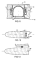
- Fig. 9-11 show different installation options of vibration absorbers in Guided missiles. The only thing left of the guided missile is the gas bottle receiving space 44 containing section 46 is shown.
- a vibration damper 48 is in the Inside a gas bottle 50 arranged in the gas bottle receiving space 44 arranged.
- the vibration damper 48 shown schematically in FIG. 9 has one Damper mass 52 and a first and a second spring-damper system 54 and 56 respectively.
- an absorber mass is also used 52 and having a first and a second spring damper system 54 and 56, respectively Vibration damper 48 used.
- the Vibration damper 48 arranged directly in the gas bottle receiving space 44, wherein there is no gas bottle.
- the gas bottle 50 itself is used as Absorber mass used.
- first and second spring damper systems 54 and 56 are arranged.
- An elastic trained Gas bottle holder 58 ensures that the gas bottle 50 in the gas bottle receiving space 44 is not rigidly attached, but can swing.
- FIG. 12 The front part of a training missile 60 is shown in FIG. In the top there is a viewfinder unit 62. Behind the viewfinder unit 62 the Training missile 60 has an empty tube in which a vibration damper 48 is arranged, which is similar to the vibration damper 48 shown in FIGS. 9 and 10 is constructed. Fig. 12 is intended to be an inexpensive installation option in training missiles demonstrate.
- 13 is the front part of a guided missile 66 and the front part of a Carrier aircraft or Launchers 68 shown. Between the missile 66 and the Launcher 68 is a vibration damper 70 is arranged. 13 is a possible Show arrangement of a vibration damper 70 in aerofoil.
Landscapes
- Engineering & Computer Science (AREA)
- General Engineering & Computer Science (AREA)
- Aviation & Aerospace Engineering (AREA)
- Chemical & Material Sciences (AREA)
- Combustion & Propulsion (AREA)
- Physics & Mathematics (AREA)
- Fluid Mechanics (AREA)
- Vibration Prevention Devices (AREA)
Abstract
Description
- Fig. 1
- ist eine schematische Darstellung und zeigt ein Schwingungsmodell eines Lenkflugkörpers, bei welchem ein Schwingungstilger im Bereich der Flugkörpernase angebracht ist.
- Fig. 2
- zeigt ein Ausführungsbeispiel des Schwingungstilgers von Fig. 1 in einer ersten Seitenansicht.
- Fig. 3
- zeigt den Schwingungstilger von Fig. 2 in einer zweiten Seitenansicht.
- Fig. 4
- zeigt den Schwingungstilger von Fig. 2 in einer dritten Seitenansicht.
- Fig. 5
- zeigt den Schwingungstilger von Fig. 2 in Draufsicht.
- Fig. 6
- ist ein erstes Kurvendiagramm und zeigt Schwingungsamplituden verschiedener Teile des Schwingungssystems von Fig. 1 in Abhängigkeit von der Anregungsfrequenz beim Weglassen des Schwingungstilgers.
- Fig. 7
- ist ein zweites Kurvendiagramm und zeigt Schwingungsamplituden verschiedener Teile des Schwingungssystems von Fig. 1 in Abhängigkeit von der Anregungsfrequenz bei ungedämpftem Schwingungstilger.
- Fig. 8
- ist ein drittes Kurvendiagramm und zeigt Schwingungsamplituden verschiedener Teile des Schwingungssystems von Fig. 1 in Abhängigkeit von der Anregungsfrequenz bei gedämpftem Schwingungstilger.
- Fig. 9-11
- zeigen verschiedene Anwendungen von Schwingungstilgern beim Einsatz in einem Lenkflugkörper.
- Fig. 12
- zeigt eine mögliche Anordnung eines Schwingungstilgers in einem Trainingsflugkörper.
- Fig. 13
- zeigt eine mögliche Anordnung eines Schwingungstilgers bei einem an einem Launcher befestigten Lenkflugkörper.
Claims (12)
- Lenkflugkörper mit einer Flugkörpernase und einem in der Flugkörpernase angeordneten Sucher, gekennzeichnet durch schwingungsdämpfende Mittel zum Verringern der mechanischen Schwingungen des Lenkflugkörpers im Flug.
- Lenkflugkörper nach Anspruch 1, dadurch gekennzeichnet, daß der Lenkflugkörper an einem Trägerflugzeug befestigbar ist und die schwingungsdämpfenden Mittel zwischen dem Lenkflugkörper und dem Trägerflugzeug angeordnete schwingungsdämpfende Komponenten aufweisen.
- Lenkflugkörper nach Anspruch 1 oder 2, dadurch gekennzeichnet, daß die schwingungsdämpfenden Mittel in dem Lenkflugkörper angeordnete schwingungsdämpfende Komponenten aufweisen.
- Lenkflugkörper nach einem der Ansprüche 1-3, dadurch gekennzeichnet, daß die schwingungsdämpfenden Mittel im Bereich der Flugkörpernase des Lenkflugkörpers angeordnete schwingungsdämpfende Komponenten aufweisen.
- Lenkflugkörper nach einem der Ansprüche 1-4, dadurch gekennzeichnet, daß der Lenkflugkörper einen Gasflaschen-Aufnahmeraum aufweist und die schwingungsdämpfende Mittel in dem Gasflaschen-Aufnahmeraum angeordnete schwingungsdämpfende Komponenten aufweisen.
- Lenkflugkörper nach einem der Ansprüche 1-5, dadurch gekennzeichnet, daß der Lenkflugkörper eine Gasflasche aufweist und die Gasflasche eine schwingungsdämpfende Komponente der schwingungsdämpfenden Mittel bildet.
- Lenkflugkörper nach einem der Ansprüche 1-6, dadurch gekennzeichnet, daß der Lenkflugkörper eine Gasflasche aufweist und schwingungsdämpfende Komponenten der schwingungsdämpfenden Mittel im Inneren der Gasflasche vorgesehen sind.
- Lenkflugkörper nach einem der Ansprüche 1-7, dadurch gekennzeichnet, daß die schwingungsdämpfenden Mittel zumindest einen Schwingungstilger aufweisen.
- Lenkflugkörper nach Anspruch 8, dadurch gekennzeichnet, daß der Schwingungstilger eine Masse, eine Federanordnung und ein Dämpfungssystem aufweist.
- Lenkflugkörper nach Anspruch 9, dadurch gekennzeichnet, daß die Federanordnung eine Blattfederanordnung, eine Gummifederanordnung, eine Schraubenfederanordnung, eine Tellerfederanordnung und/oder eine Drehfederanordnung aufweist.
- Lenkflugkörper nach Anspruch 9 oder 10, dadurch gekennzeichnet, daß das Dämpfungssystem ein Reibdämpfungssystem, ein viskoses Dämpfungssystem, ein Wirbelstromdämpfungssystem und/oder ein Gummidämpfungssystem aufweist.
- Verwendung eines Schwingungstilgers zur Schwingungsreduzierung eines Lenkflugkörpers.
Applications Claiming Priority (2)
| Application Number | Priority Date | Filing Date | Title |
|---|---|---|---|
| DE10127623 | 2001-06-07 | ||
| DE2001127623 DE10127623A1 (de) | 2001-06-07 | 2001-06-07 | Lenkflugkörper |
Publications (2)
| Publication Number | Publication Date |
|---|---|
| EP1281927A1 true EP1281927A1 (de) | 2003-02-05 |
| EP1281927B1 EP1281927B1 (de) | 2006-07-26 |
Family
ID=7687491
Family Applications (1)
| Application Number | Title | Priority Date | Filing Date |
|---|---|---|---|
| EP20020011222 Expired - Lifetime EP1281927B1 (de) | 2001-06-07 | 2002-05-18 | Lenkflugkörper |
Country Status (2)
| Country | Link |
|---|---|
| EP (1) | EP1281927B1 (de) |
| DE (2) | DE10127623A1 (de) |
Families Citing this family (2)
| Publication number | Priority date | Publication date | Assignee | Title |
|---|---|---|---|---|
| RU2409801C2 (ru) * | 2009-04-07 | 2011-01-20 | Пензенский Артиллерийский Инженерный Институт | Способ снижения вероятности разрушения снарядов реактивной системы залпового огня (рсзо) в полете, основанный на снижении влияния флаттерных колебаний |
| RU189881U1 (ru) * | 2018-12-29 | 2019-06-07 | Алексей Владимирович Молоствов | Защищенный электронно-временной воспламенитель для малогабаритных ракетных двигателей |
Citations (7)
| Publication number | Priority date | Publication date | Assignee | Title |
|---|---|---|---|---|
| US3351307A (en) * | 1964-05-06 | 1967-11-07 | Dassault Electronique | Damped suspension system |
| US3566993A (en) * | 1969-03-26 | 1971-03-02 | Nasa | Active vibration isolator for flexible bodies |
| DE2036979A1 (de) * | 1970-07-25 | 1972-02-03 | Hamburger Flugzeugbau Gmbh | Schwingungstilger zum Verringern von Korperschall |
| US4155286A (en) * | 1977-12-01 | 1979-05-22 | Mihm John J | Wedge clamp for missile launcher |
| US4309005A (en) * | 1976-06-17 | 1982-01-05 | Walter G. Finch | Target seeking gyro |
| DE19711846A1 (de) * | 1997-03-21 | 1998-10-29 | Eurocopter Deutschland | Mechanischer Schwingungstilger |
| US5855260A (en) * | 1996-12-13 | 1999-01-05 | The Aerospace Corporation | Tuned broadband particulate vibration absorber |
-
2001
- 2001-06-07 DE DE2001127623 patent/DE10127623A1/de not_active Withdrawn
-
2002
- 2002-05-18 DE DE50207608T patent/DE50207608D1/de not_active Expired - Fee Related
- 2002-05-18 EP EP20020011222 patent/EP1281927B1/de not_active Expired - Lifetime
Patent Citations (7)
| Publication number | Priority date | Publication date | Assignee | Title |
|---|---|---|---|---|
| US3351307A (en) * | 1964-05-06 | 1967-11-07 | Dassault Electronique | Damped suspension system |
| US3566993A (en) * | 1969-03-26 | 1971-03-02 | Nasa | Active vibration isolator for flexible bodies |
| DE2036979A1 (de) * | 1970-07-25 | 1972-02-03 | Hamburger Flugzeugbau Gmbh | Schwingungstilger zum Verringern von Korperschall |
| US4309005A (en) * | 1976-06-17 | 1982-01-05 | Walter G. Finch | Target seeking gyro |
| US4155286A (en) * | 1977-12-01 | 1979-05-22 | Mihm John J | Wedge clamp for missile launcher |
| US5855260A (en) * | 1996-12-13 | 1999-01-05 | The Aerospace Corporation | Tuned broadband particulate vibration absorber |
| DE19711846A1 (de) * | 1997-03-21 | 1998-10-29 | Eurocopter Deutschland | Mechanischer Schwingungstilger |
Also Published As
| Publication number | Publication date |
|---|---|
| DE50207608D1 (de) | 2006-09-07 |
| DE10127623A1 (de) | 2002-12-12 |
| EP1281927B1 (de) | 2006-07-26 |
Similar Documents
| Publication | Publication Date | Title |
|---|---|---|
| EP2978991B1 (de) | Schwingungsdämpfer für abschirmblech | |
| DE202011000635U1 (de) | Schwingungsfreie Lagerung eines Objekts an einer schwingenden Struktur | |
| DE102010023228A1 (de) | Stabilisierungseinrichtung | |
| DE102008039981B3 (de) | Vorrichtung zur anteiligen Kompensation der Schwerkraft auf ein Testobjekt | |
| EP0347545A1 (de) | Vorrichtung zum Vermindern von Karosserieschwingungen | |
| DE3304849C2 (de) | ||
| DE2035764C3 (de) | Schwingungstilger | |
| DE102016200129A1 (de) | Fliehkraftpendel | |
| DE102010038782A1 (de) | Drehschwingungstilger mit zweiarmigem Pendel | |
| EP0349979B1 (de) | Anordnung zur Dämpfung von Schwingungen an Bauwerken oder Bauteilen | |
| EP1281927A1 (de) | Lenkflugkörper | |
| DE1267955B (de) | Torsionsstimmgabel | |
| DE202010000199U1 (de) | Einstellbare Schwingungstilgervorrichtung für ein Robotersystem | |
| DE4200744A1 (de) | Verfahren und vorrichtung zur daempfung von unerwuenschten schwingungen eines fahrzeugaussenspiegels | |
| EP1327726A1 (de) | Einstellbarer Schwingungstilger | |
| DE1623642A1 (de) | Halterungssystem | |
| DE3816033C2 (de) | ||
| DE102008052424B4 (de) | Vibrationstilgersystem | |
| DE102016200394B4 (de) | Verfahren zur Steuerung eines Schwingungssystems und Aktuator | |
| DE602004002901T2 (de) | Vorrichtung zur aktiven Dämpfung von Schwingungen einer Waffe | |
| DE10210032C1 (de) | Passiver Schwingungstilger | |
| DE10227968B4 (de) | Lagerungssystem in einem Raumfahrzeug | |
| DE3935893C2 (de) | ||
| DE102004043135B3 (de) | Aktiver Schwingungstilger | |
| DE102016013646B3 (de) | Auf die Kadenz einer Waffe abgestimmter Dämpfer |
Legal Events
| Date | Code | Title | Description |
|---|---|---|---|
| PUAI | Public reference made under article 153(3) epc to a published international application that has entered the european phase |
Free format text: ORIGINAL CODE: 0009012 |
|
| AK | Designated contracting states |
Designated state(s): AT BE CH CY DE DK ES FI FR GB GR IE IT LI LU MC NL PT SE TR |
|
| AX | Request for extension of the european patent |
Extension state: AL LT LV MK RO SI |
|
| 17P | Request for examination filed |
Effective date: 20021005 |
|
| AKX | Designation fees paid |
Designated state(s): DE FR GB |
|
| 17Q | First examination report despatched |
Effective date: 20040713 |
|
| RAP1 | Party data changed (applicant data changed or rights of an application transferred) |
Owner name: DIEHL BGT DEFENCE GMBH & CO.KG |
|
| GRAP | Despatch of communication of intention to grant a patent |
Free format text: ORIGINAL CODE: EPIDOSNIGR1 |
|
| GRAS | Grant fee paid |
Free format text: ORIGINAL CODE: EPIDOSNIGR3 |
|
| GRAA | (expected) grant |
Free format text: ORIGINAL CODE: 0009210 |
|
| AK | Designated contracting states |
Kind code of ref document: B1 Designated state(s): DE FR GB |
|
| REG | Reference to a national code |
Ref country code: GB Ref legal event code: FG4D Free format text: NOT ENGLISH |
|
| REF | Corresponds to: |
Ref document number: 50207608 Country of ref document: DE Date of ref document: 20060907 Kind code of ref document: P |
|
| GBT | Gb: translation of ep patent filed (gb section 77(6)(a)/1977) |
Effective date: 20061016 |
|
| ET | Fr: translation filed | ||
| PLBE | No opposition filed within time limit |
Free format text: ORIGINAL CODE: 0009261 |
|
| STAA | Information on the status of an ep patent application or granted ep patent |
Free format text: STATUS: NO OPPOSITION FILED WITHIN TIME LIMIT |
|
| 26N | No opposition filed |
Effective date: 20070427 |
|
| PGFP | Annual fee paid to national office [announced via postgrant information from national office to epo] |
Ref country code: FR Payment date: 20090513 Year of fee payment: 8 |
|
| PGFP | Annual fee paid to national office [announced via postgrant information from national office to epo] |
Ref country code: DE Payment date: 20090722 Year of fee payment: 8 Ref country code: GB Payment date: 20090522 Year of fee payment: 8 |
|
| GBPC | Gb: european patent ceased through non-payment of renewal fee |
Effective date: 20100518 |
|
| REG | Reference to a national code |
Ref country code: FR Ref legal event code: ST Effective date: 20110131 |
|
| PG25 | Lapsed in a contracting state [announced via postgrant information from national office to epo] |
Ref country code: DE Free format text: LAPSE BECAUSE OF NON-PAYMENT OF DUE FEES Effective date: 20101201 |
|
| PG25 | Lapsed in a contracting state [announced via postgrant information from national office to epo] |
Ref country code: FR Free format text: LAPSE BECAUSE OF NON-PAYMENT OF DUE FEES Effective date: 20100531 |
|
| PG25 | Lapsed in a contracting state [announced via postgrant information from national office to epo] |
Ref country code: GB Free format text: LAPSE BECAUSE OF NON-PAYMENT OF DUE FEES Effective date: 20100518 |