EP1279328B1 - Verfahren und Vorrichtung zur Unterbrechung oder Ausbildung einer strömungstechnischen Verbindung zwischen wenigstens einem Melkbecher und einer Milchleitung - Google Patents
Verfahren und Vorrichtung zur Unterbrechung oder Ausbildung einer strömungstechnischen Verbindung zwischen wenigstens einem Melkbecher und einer Milchleitung Download PDFInfo
- Publication number
- EP1279328B1 EP1279328B1 EP02013574A EP02013574A EP1279328B1 EP 1279328 B1 EP1279328 B1 EP 1279328B1 EP 02013574 A EP02013574 A EP 02013574A EP 02013574 A EP02013574 A EP 02013574A EP 1279328 B1 EP1279328 B1 EP 1279328B1
- Authority
- EP
- European Patent Office
- Prior art keywords
- passage
- chamber
- pressure
- valve member
- membrane
- Prior art date
- Legal status (The legal status is an assumption and is not a legal conclusion. Google has not performed a legal analysis and makes no representation as to the accuracy of the status listed.)
- Expired - Lifetime
Links
Images
Classifications
-
- A—HUMAN NECESSITIES
- A01—AGRICULTURE; FORESTRY; ANIMAL HUSBANDRY; HUNTING; TRAPPING; FISHING
- A01J—MANUFACTURE OF DAIRY PRODUCTS
- A01J5/00—Milking machines or devices
- A01J5/04—Milking machines or devices with pneumatic manipulation of teats
- A01J5/041—Milk claw
-
- A—HUMAN NECESSITIES
- A01—AGRICULTURE; FORESTRY; ANIMAL HUSBANDRY; HUNTING; TRAPPING; FISHING
- A01J—MANUFACTURE OF DAIRY PRODUCTS
- A01J5/00—Milking machines or devices
- A01J5/007—Monitoring milking processes; Control or regulation of milking machines
-
- A—HUMAN NECESSITIES
- A01—AGRICULTURE; FORESTRY; ANIMAL HUSBANDRY; HUNTING; TRAPPING; FISHING
- A01J—MANUFACTURE OF DAIRY PRODUCTS
- A01J5/00—Milking machines or devices
- A01J5/04—Milking machines or devices with pneumatic manipulation of teats
- A01J5/044—Milk lines or coupling devices for milk conduits
Definitions
- the object of the invention relates to a method and an apparatus to interrupt or form a fluidic connection between at least one milking cup and a milk line.
- EP 0 903 078 A1 describes a teat cup arrangement with an entry opening having teat receptacle by an elastic teat sleeve is known.
- the teat cup arrangement has a connecting piece for a milking line, one in the flow path below the teat receptacle Valve arrangement is formed with a valve chamber, which has a valve body through which the flow path is closed in a closed position and is open in an open position.
- On the teat cup sleeve is one with the valve body connected actuator provided for closing the Flow path away from the inlet opening or to open the flow path is displaceable in the direction of the inlet opening.
- EP 0 566 977 A1 describes a shutoff valve in a suction line, in particular known for mounting in the lower area of a milking cup.
- the final valve has a between an open and a closed position reversible valve element interacting with a membrane.
- the reversal process is either automatic depending on the im Pressure inside the teat cup interior.
- a manual opening or closing The valve is moved by moving the teat cup in the axial direction or by moving the teat cup sideways.
- the membrane is ring-shaped educated. It is shaped in such a way that after overcoming it, practical a snap position representing the middle position in both end positions remains as shown in Figures 1 and 2 of EP 0 566 977 A1.
- the membrane forms part of the short milk tube. It exists hence the risk that due to the force on the milking cup or the membrane jumps back into position on the short milking hose, in which the shut-off valve is opened or closed unintentionally.
- GB-A-737,834 discloses a method and device for interruption or forming a fluidic connection between at least a milking cup and a milk line in which a negative pressure prevails.
- a valve body Within a chamber located in a milk flow path a valve body is provided.
- the valve body interacts with a spring. The spring pushes the valve body away from a valve seat when the Milking cup is attached to a teat of an animal.
- the present invention is based on the objective of a method and an apparatus for interrupting or forming a fluidic connection between at least one milking cup and to specify a milk pipeline through which or through which is that a fluidic connection is only made when the milking cluster has been attached.
- Another aim is to specify a method or a device by which it is ensured that when a milking cup falls off, the fluidic connection is interrupted.
- a method of interruption or Formation of a fluidic connection between a milking cup and a milk line in which there is negative pressure In the milk flow path a device is provided.
- the device has a membrane, which partially delimits a chamber with a connecting piece.
- a valve member is provided which interacts with the membrane.
- the Valve member is by a first valve body and a second valve body educated.
- a passage is formed in the milk flow path, which passes through the first or the second valve body is closable.
- There is also a bypass channel provided that viewed in the direction of flow of milk, the room in front connects the culvert to a space behind the culvert.
- the chamber first use a pressure is applied which is greater than that prevailing in the milking line Vacuum. Before or during the preparation of the at least one Bechers on a teat, the chamber is pressurized, which in the essentially corresponds to the negative pressure prevailing in the milk milking line.
- the chamber is initially subjected to a pressure that is greater is than the negative pressure prevailing in the milking line, it is achieved that the first valve body closes the passage and the bypass channel.
- the first valve body closes the passage and the bypass channel.
- the membrane becomes deflected so that the first valve body the passage and the bypass channel releases, the second valve body the passage up to the bypass channel closes.
- the attached milking cup makes the supply more atmospheric Air prevented. Through the bypass duct is in the room Negative pressure generated.
- the second valve body which follows the movement of the diaphragm, the Passage up to the bypass channel.
- the free cross-sectional area of the bypass channel is preferably so low that it is preferred by the air movement no or only slight vacuum fluctuations and suction comes from dirt.
- the chamber is essentially pressurized at the end of milking is sufficiently large that the first valve body the passage and the Bypass channel closes.
- This procedure has the advantage that a switching process of the valve can take place as long as the at least one teat cup lies against the teat of an animal, especially a cow. After acceptance of the milking cup there is no pressure fluctuation in the milk line.
- the chamber be pressurized which corresponds essentially to the pressure which prevailed before the start of a milking cup in the chamber.
- the pressure initially prevailing in the chamber is an atmospheric pressure equivalent.
- a device for interruption and forming a fluidic connection between at least a teat cup and a milk line in which a vacuum prevails proposed.
- the device has a cooperating with a membrane Valve organ on.
- the membrane partially delimits a chamber, which has a connecting piece.
- a bypass channel is also provided, who looks in the direction of milk flow into a space in front of a passage connects to a space behind the culvert.
- the valve member is there formed so that this depending on the position of the valve member Passage or the passage and the bypass channel closes respectively releases.
- This device according to the invention creates the possibility of that at least one teat cup is only vacuumed when the teat of an animal is in the milking cup.
- This device according to the invention can directly on the teat cup or in the flow path be arranged between the teat cup and milk line. It is preferably in every flow path between the teat cup and the milking line of a milking cluster a device according to the invention is provided.
- the teat cup according to the invention Device an automatic shutoff of the passage, wherein the bypass channel remains open, reaching vacuum breaks in the Milk pipe and the intake of contaminated air with dirt particles in the can be substantially avoided.
- the valve member has a first and a second valve body that are rigid with each other are connected, wherein the passage between the valve bodies is formed.
- the valve bodies only release the passage when the Membrane is essentially no pressure difference.
- valve member guided in a guide becomes.
- the valve member preferably has a guide rod, which in a channel is led.
- the channel be connected to the connecting piece is.
- the cross section of the channel and the cross section of the guide rod are dimensioned so that there is always a fluidic connection between the chamber and the connecting piece is ensured.
- At least one sensor for detecting the position of the valve body is provided.
- the operator can use the signaling device be made aware that a teat cup is from a teat fell.
- the sensor is preferably a proximity sensor.
- the sensor be designed as a Hall sensor.
- the sensor is preferably arranged in the region of the channel.
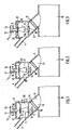
- Figure 1 shows an embodiment of an inventive device for Interruption or formation of a fluidic connection between a teat cup, not shown, and a milk line 12 in which a There is negative pressure.
- the device has a housing 1.
- the housing 1 is formed in two parts. It has a lower part 2 and an upper part 3.
- the upper part 3 and the lower part 2 are connected to each other in a gas-tight manner.
- An inlet connection opens into the lower part 2 4, over a milking hose, not shown, with a milking cup connected is.
- the lower part 2 also has an outlet connection 5, which has a milk line 12 is connected. Between the inlet nozzle 4 and the outlet nozzle 5 a wall 10 is arranged which has a passage 11. In the wall 10 is a bypass channel 13 is also provided. The cross section of the bypass channel 13 is significantly smaller than the cross section of the passage 11.
- a valve member 7 is connected to the membrane 6.
- the valve member 7 has a first valve body 8 and a second valve body 18.
- the first valve body 8 and the second valve body 18 are by means of a connecting piece 9 rigidly connected. This extends through the passage 11, so that the passage 11 lies between the valve bodies 8, 18.
- the first valve body 8 is designed such that it is in a closed position closes both the passage 11 and the bypass channel 13.
- the second valve body 18 is conical educated.
- the conical design of the valve body 18 represents in it is essentially certain that only the passage 11 is made possible by the second valve body 18.
- the valve member 7 is connected to a guide rod 16.
- the guide rod 16 extends into a channel 15 which is formed in the upper part 3 of the housing is.
- the guide rod 16 is slidably guided in the channel 15.
- a connecting piece 14 is formed, the fluidic is connected to the channel 15.
- the channel 15 and the guide rod 16 have such cross-sectional shapes that a gas over the connecting piece 14 into a through the membrane 6 and the upper part 3 limited chamber 22 can flow.
- the volume of the chamber 22 is variable.
- the chamber 22 is over the connection piece 14 connected to a pressure source, not shown.
- the membrane 6 is in the illustrated embodiment between the upper part 3 and the lower part 2 of the housing 1 set. It has a circumferential Wave 23 on, as shown in Figure 2.
- the membrane 6 is made preferably completely made of an elastic material. It can be enough be if only the shaft 23 is made of an elastic material.
- Figure 1 shows the device in an initial configuration in which no milking cup is attached to a teat of an animal.
- the milking cup is not over one Milking hose shown connected to the inlet connection 4.
- the chamber 22 is pressurized to a pressure which is greater than that in the Milking line 12 prevailing negative pressure.
- the chamber 22 can Connection piece 14 to be connected to the surrounding atmosphere, so that in the Chamber 22 ambient pressure prevails. Since in the chamber 22 ambient pressure is present and there is a negative pressure in the space 20, the membrane 6 is in the direction of the passage 11 deflected. The deflection of the membrane 6 is sufficient large, so that the second valve body 18, the passage 11 and the bypass channel 13 closes.
- the chamber 22 pressurized via the connecting piece 14 with a pressure that essentially corresponds to the negative pressure prevailing in the milking line 12.
- room 20 there is atmospheric pressure because the teat cup connected to the inlet connection 4 is in connection with the surrounding atmosphere.
- the first valve body 8 gives the passage 11 and the bypass channel 13 free, the second valve body 18, the passage 11 except for the bypass channel 13 closes while the teat cup is being attached, as shown in FIG. 3 is shown.
- the teat cup can approximate no more atmospheric air flows in, so that in room 20 via the bypass duct 13 the same pressure is built up as in chamber 22.
- Die Membrane 6 assumes its neutral position, as shown in FIG. 2. Neither the first valve body 8 nor the second valve body 18 close the Passage 11 in the neutral position of the membrane 6.
- the teat cup If the teat cup is knocked off during milking, it flows over the open milking cup atmospheric air, so that there is 20 atmospheric pressure in the room established. Since there is still a negative pressure in the chamber 22, which corresponds to the negative pressure in the milk line 12, the membrane 6 in Direction of the connecting piece 14 moves, the second valve body 18 to System comes to the edge of the passage 11 and closes it, the Bypass channel 13 remains open.
- Figure 3 shows the position of the valve member 7 if the teat cup is removed from a teat during a milking process fell.
- the sensor 17 is preferably connected to a signal device, which signals to a milker that a milking cup has fallen off.
- the room 20 and the room 21 are connected to one another by the bypass channel 13. If the fallen teat cup is brought back to the teat of an animal, a negative pressure forms in the room 20, which is at a complete Formation of the negative pressure corresponds to the pressure in the chamber 22. Thereby conditionally there is no pressure difference on the membrane 6, so that the membrane 6 reaches the neutral position, as shown in Figure 2.
- the valve organ 7 moves simultaneously with the membrane 6.
- the second valve body 18 opens the passage 11, so that a fluidic connection between the teat cup and milk line 12 is restored. This The situation is shown in Figure 2.
- FIG. 1 shows that two electrodes 19 are provided in the outlet connection 5, which are used to determine the milk flow. Instead of the electrodes 19 can also other devices are provided that determine the milk flow.
- the size The milk flow is a characteristic parameter for the course of a milking process on an animal. Is recognizable from the course of the milk flow over time, that a milking end is approaching, the chamber 22 is over the connecting piece 14 connected to the ambient atmosphere, so that the second valve body 18 closes the passage 11.
- the device according to the invention is particularly suitable in connection with Milk cups that have a cyclical air inlet to improve milk transport to have.
- This air intake can occur during the attachment of the milking cup be prevented so that a faster vacuum builds up in the teat cup and the valve element even with very small diameters of the bypass channel releases the passage after a very short time.
Landscapes
- Life Sciences & Earth Sciences (AREA)
- Animal Husbandry (AREA)
- Environmental Sciences (AREA)
- External Artificial Organs (AREA)
- Sanitary Device For Flush Toilet (AREA)
- Measuring Fluid Pressure (AREA)
Description
- Fig. 1
- schematisch ein Ausführungsbeispiel einer erfindungsgemäßen Vorrichtung, wobei die strömungstechnische Verbindung zwischen wenigstens einem Melkbecher und einer Milchleitung vollständig unterbrochen ist,
- Fig. 2
- die Vorrichtung nach Figur 1, wobei eine strömungstechnische Verbindung gegeben ist und
- Fig. 3
- schematisch die Vorrichtung nach Figur 1, wobei die strömungstechnische Verbindung bis auf einen Bypass-Kanal unterbrochen ist.
- 1
- Gehäuse
- 2
- Unterteil
- 3
- Oberteil
- 4
- Zulaufstutzen
- 5
- Ablaufstutzen
- 6
- Membrane
- 7
- Ventilorgan
- 8
- erster Ventilkörper
- 9
- Verbindungsstück
- 10
- Wand
- 11
- Durchlass
- 12
- Milchleitung
- 13
- Bypass-Kanal
- 14
- Anschlussstutzen
- 15
- Kanal
- 16
- Führungsstange
- 17
- Sensor
- 18
- zweiter Ventilkörper
- 19
- Elektrode
- 20
- Raum
- 21
- Raum
- 22
- Kammer
- 23
- Welle
Claims (12)
- Verfahren zur Unterbrechung oder Ausbildung einer strömungstechnischen Verbindung zwischen wenigsten einem Melkbecher und einer Milchleitung (12), in der ein Unterdruck herrscht, wobei im Milch-Strömungsweg eine Vorrichtung vorgesehen ist, wobei die Vorrichtung ein mit einer Membrane (6) zusammenwirkendes Ventilorgan (7) aufweist, die Membrane (6) teilweise eine Kammer (22) mit einem Anschlussstutzen (14) begrenzt, und ein Bypass-Kanal (13) vorgesehen ist, der in Strömungsrichtung der Milch betrachtet einen Raum (20) vor einem Durchlass (11) mit einem Raum (21) hinter dem Durchlass (11) verbindet, wobei das Ventilorgan (7) so ausgebildet ist, dass dieses entweder den Durchlass (11) oder den Durchlass (11) und den Bypass-Kanal (13) verschließt bzw. freigibt, bei dem zunächst die Kammer (22) mit einem Druck beaufschlagt wird, der größer ist als der in der Milchleitung (12) herrschende Druck, die Kammer (22) wenigstens vor oder während eines Ansetzens des mindestens einen Melkbechers an eine Zitze mit einem Druck beaufschlagt wird, der im wesentlichen dem in der Melkleitung (12) herrschenden Unterdruck entspricht.
- Verfahren nach Anspruch 1, bei dem die Kammer (22) im wesentlichen beim Melkende mit einem Druck beaufschlagt wird, der ausreichend groß ist, dass das Ventilorgan (7) den Durchlass (11) und den Bypass-Kanal (13) verschließt.
- Verfahren nach Anspruch 1 oder 2, bei dem die Kammer (22) im wesentlichen beim Melkende mit einem Druck beaufschlagt wird, der im wesentlichen dem zunächst in der Kammer (22) herrschenden Druck entspricht.
- Verfahren nach Anspruch 1, 2 oder 3, bei dem der zunächst in der Kammer (22) herrschende Druck einem Atmosphärendruck entspricht.
- Vorrichtung zur Unterbrechung oder Ausbildung einer strömungstechnischen Verbindung zwischen wenigsten einem Melkbecher und einer Milchleitung (12), in der ein Unterdruck herrscht, wobei die Vorrichtung ein mit einer Membrane (6) zusammenwirkendes Ventilorgan (7) aufweist, die Membrane (6) teilweise eine Kammer (22) mit einem Anschlussstutzen (14) begrenzt, und ein Bypass-Kanal (13) vorgesehen ist, der in Strömungsrichtung der Milch betrachtet einen Raum (20) vor einem Durchlass (11) mit einem Raum (21) hinter dem Durchlass (11) verbindet, wobei das Ventilorgan (7) so ausgebildet ist, dass dieses entweder den Durchlass (11) oder den Durchlass (11) und den Bypass-Kanal (13) verschließt bzw. freigibt.
- Vorrichtung nach Anspruch 5, dadurch gekennzeichnet, dass das Ventilorgan (7) einen ersten (8) und einen zweiten (18) Ventilkörper, die starr miteinander verbunden sind, aufweist, zwischen denen der Durchlass (11) angeordnet ist, wobei durch den ersten (8) Ventilkörper der Durchlass (11) und der Bypass-Kanal (13) verschließbar sind.
- Vorrichtung nach Anspruch 5 oder 6 dadurch gekennzeichnet, dass das Ventilorgan (7) in einer Führung (15, 16) geführt ist.
- Vorrichtung nach Anspruch 7, dadurch gekennzeichnet, dass das Ventilorgan (7) eine Führungsstange (16) aufweist, die in einem Kanal (15) geführt ist.
- Vorrichtung nach Anspruch 8, dadurch gekennzeichnet, dass der Kanal (15) mit dem Anschlussstutzen (14) verbunden ist.
- Vorrichtung nach einem der Ansprüche 5 bis 9, dadurch gekennzeichnet, dass wenigstens ein Sensor (17) zur Detektion der Position des Ventilorgans (7) vorgesehen ist.
- Vorrichtung nach Anspruch 8 und 10, dadurch gekennzeichnet, dass der Sensor (17) im Bereich des Kanals (15) angeordnet ist.
- Vorrichtung nach Anspruch 10 oder 11, dadurch gekennzeichnet, dass der Sensor (17) ein Näherungssensor ist.
Applications Claiming Priority (2)
| Application Number | Priority Date | Filing Date | Title |
|---|---|---|---|
| DE10136091A DE10136091B4 (de) | 2001-07-26 | 2001-07-26 | Verfahren und Vorrichtung zur Unterbrechung oder Ausbildung einer strömungstechnischen Verbindung zwischen wenigstens einem Melkbecher und einer Melkleitung |
| DE10136091 | 2001-07-26 |
Publications (3)
| Publication Number | Publication Date |
|---|---|
| EP1279328A2 EP1279328A2 (de) | 2003-01-29 |
| EP1279328A3 EP1279328A3 (de) | 2003-07-23 |
| EP1279328B1 true EP1279328B1 (de) | 2004-08-25 |
Family
ID=7692954
Family Applications (1)
| Application Number | Title | Priority Date | Filing Date |
|---|---|---|---|
| EP02013574A Expired - Lifetime EP1279328B1 (de) | 2001-07-26 | 2002-06-20 | Verfahren und Vorrichtung zur Unterbrechung oder Ausbildung einer strömungstechnischen Verbindung zwischen wenigstens einem Melkbecher und einer Milchleitung |
Country Status (5)
| Country | Link |
|---|---|
| EP (1) | EP1279328B1 (de) |
| AT (1) | ATE274294T1 (de) |
| DE (2) | DE10136091B4 (de) |
| DK (1) | DK1279328T3 (de) |
| ES (1) | ES2227365T3 (de) |
Cited By (1)
| Publication number | Priority date | Publication date | Assignee | Title |
|---|---|---|---|---|
| DE102022117866A1 (de) * | 2022-07-18 | 2024-01-18 | Gea Farm Technologies Gmbh | Vorrichtung und Verfahren zur Kontrolle eines Melkprozesses |
Family Cites Families (5)
| Publication number | Priority date | Publication date | Assignee | Title |
|---|---|---|---|---|
| GB194288A (en) * | 1922-03-01 | 1924-03-06 | Separator Ab | Improvements in or relating to automatic valve devices |
| GB737834A (en) * | 1953-10-27 | 1955-10-05 | Louise Ronaldson | Automatic cut-off valve for milking apparatus |
| US2986117A (en) * | 1959-05-19 | 1961-05-30 | Ronaldson Louise | Milking machine teat cups |
| DE4212911A1 (de) * | 1992-04-18 | 1993-10-21 | Fritz Happel | Abschlußventil in einer Saugleitung |
| DE19740537C2 (de) * | 1997-09-15 | 2001-12-13 | Westfalia Landtechnik Gmbh | Melkbecheranordnung mit einem Ventil |
-
2001
- 2001-07-26 DE DE10136091A patent/DE10136091B4/de not_active Expired - Fee Related
-
2002
- 2002-06-20 DK DK02013574T patent/DK1279328T3/da active
- 2002-06-20 EP EP02013574A patent/EP1279328B1/de not_active Expired - Lifetime
- 2002-06-20 DE DE50200887T patent/DE50200887D1/de not_active Expired - Lifetime
- 2002-06-20 ES ES02013574T patent/ES2227365T3/es not_active Expired - Lifetime
- 2002-06-20 AT AT02013574T patent/ATE274294T1/de not_active IP Right Cessation
Cited By (1)
| Publication number | Priority date | Publication date | Assignee | Title |
|---|---|---|---|---|
| DE102022117866A1 (de) * | 2022-07-18 | 2024-01-18 | Gea Farm Technologies Gmbh | Vorrichtung und Verfahren zur Kontrolle eines Melkprozesses |
Also Published As
| Publication number | Publication date |
|---|---|
| DK1279328T3 (da) | 2004-12-27 |
| DE10136091B4 (de) | 2005-01-27 |
| ES2227365T3 (es) | 2005-04-01 |
| DE10136091A1 (de) | 2003-02-20 |
| ATE274294T1 (de) | 2004-09-15 |
| EP1279328A3 (de) | 2003-07-23 |
| EP1279328A2 (de) | 2003-01-29 |
| DE50200887D1 (de) | 2004-09-30 |
Similar Documents
| Publication | Publication Date | Title |
|---|---|---|
| DE69006460T2 (de) | Melkbecher für eine hydraulische Melkmaschine. | |
| DE102008063715B4 (de) | Milchsammelstück mit verschließbaren Kammern | |
| DE4343205A1 (de) | Als Sicherheitsventilanordnung bei medizinischen Beatmungsgeräten einsetzbare Ventilanordnung | |
| DE4109337A1 (de) | Verschlusskappenlose fahrzeug-auftankvorrichtung | |
| DE102008061753A1 (de) | Druckregelventil | |
| DE69207723T2 (de) | Entlüftungsventil | |
| EP0903078B1 (de) | Melkbecheranordnung mit einem Ventil | |
| DE2927073A1 (de) | Einrichtung zum abfuehlen eines fluessigkeitsstromes, insbesondere eines milchstromes bei melkmaschinen | |
| EP0566977A1 (de) | Abschlussventil für eine Saugleitung | |
| DE3043038A1 (de) | Vorrichtung zum verschliessen einer fluessigkeitsleitung | |
| DE10136091B4 (de) | Verfahren und Vorrichtung zur Unterbrechung oder Ausbildung einer strömungstechnischen Verbindung zwischen wenigstens einem Melkbecher und einer Melkleitung | |
| EP0160933B1 (de) | Melkvorrichtung mit einem Sammelstück | |
| EP1679955B1 (de) | Vorrichtung und verfahren zum automatischen starten eines melkvorgangs | |
| EP0675987B1 (de) | Absaugvorrichtung | |
| DE10329428B4 (de) | Vorrichtung zum Absperren und/oder Steuern und/oder Regeln eines Luftstroms | |
| DE60011258T2 (de) | Vorrichtung für einen Behälter | |
| DE102006048454B3 (de) | Vorrichtung zur Ansteuerung eines Quetschventils | |
| DE102014100797B4 (de) | Anordnung zum Absaugen von Flüssigkeit | |
| EP2023713B1 (de) | Milchsammelstück, insbesondere für ziegen und schafe | |
| DE102998C (de) | ||
| CH707132A1 (de) | Milchsammelstück mit integrierten Absperrelementen. | |
| DE2141241C3 (de) | Pneu matische Entstaubungsvorrichtung | |
| DE251928C (de) | ||
| DE2425911A1 (de) | Druckverstaerker | |
| DE3706727A1 (de) | Ventileinrichtung |
Legal Events
| Date | Code | Title | Description |
|---|---|---|---|
| PUAI | Public reference made under article 153(3) epc to a published international application that has entered the european phase |
Free format text: ORIGINAL CODE: 0009012 |
|
| AK | Designated contracting states |
Designated state(s): AT BE CH CY DE DK ES FI FR GB GR IE IT LI LU MC NL PT SE TR |
|
| AX | Request for extension of the european patent |
Extension state: AL LT LV MK RO SI |
|
| PUAL | Search report despatched |
Free format text: ORIGINAL CODE: 0009013 |
|
| AK | Designated contracting states |
Designated state(s): AT BE CH CY DE DK ES FI FR GB GR IE IT LI LU MC NL PT SE TR |
|
| AX | Request for extension of the european patent |
Extension state: AL LT LV MK RO SI |
|
| RIC1 | Information provided on ipc code assigned before grant |
Ipc: 7A 01J 5/007 B Ipc: 7A 01J 7/00 B Ipc: 7A 01J 5/04 A Ipc: 7A 01J 5/08 B |
|
| 17P | Request for examination filed |
Effective date: 20030627 |
|
| RAP1 | Party data changed (applicant data changed or rights of an application transferred) |
Owner name: WESTFALIASURGE GMBH |
|
| 17Q | First examination report despatched |
Effective date: 20031006 |
|
| GRAP | Despatch of communication of intention to grant a patent |
Free format text: ORIGINAL CODE: EPIDOSNIGR1 |
|
| AKX | Designation fees paid |
Designated state(s): AT BE CH CY DE DK ES FI FR GB GR IE IT LI LU MC NL PT SE TR |
|
| GRAS | Grant fee paid |
Free format text: ORIGINAL CODE: EPIDOSNIGR3 |
|
| GRAA | (expected) grant |
Free format text: ORIGINAL CODE: 0009210 |
|
| AK | Designated contracting states |
Kind code of ref document: B1 Designated state(s): AT BE CH CY DE DK ES FI FR GB GR IE IT LI LU MC NL PT SE TR |
|
| PG25 | Lapsed in a contracting state [announced via postgrant information from national office to epo] |
Ref country code: TR Free format text: LAPSE BECAUSE OF FAILURE TO SUBMIT A TRANSLATION OF THE DESCRIPTION OR TO PAY THE FEE WITHIN THE PRESCRIBED TIME-LIMIT Effective date: 20040825 Ref country code: FI Free format text: LAPSE BECAUSE OF FAILURE TO SUBMIT A TRANSLATION OF THE DESCRIPTION OR TO PAY THE FEE WITHIN THE PRESCRIBED TIME-LIMIT Effective date: 20040825 Ref country code: IE Free format text: LAPSE BECAUSE OF FAILURE TO SUBMIT A TRANSLATION OF THE DESCRIPTION OR TO PAY THE FEE WITHIN THE PRESCRIBED TIME-LIMIT Effective date: 20040825 |
|
| REG | Reference to a national code |
Ref country code: GB Ref legal event code: FG4D Free format text: NOT ENGLISH |
|
| REG | Reference to a national code |
Ref country code: CH Ref legal event code: EP |
|
| REG | Reference to a national code |
Ref country code: IE Ref legal event code: FG4D Free format text: GERMAN |
|
| REF | Corresponds to: |
Ref document number: 50200887 Country of ref document: DE Date of ref document: 20040930 Kind code of ref document: P |
|
| REG | Reference to a national code |
Ref country code: SE Ref legal event code: TRGR |
|
| REG | Reference to a national code |
Ref country code: GR Ref legal event code: EP Ref document number: 20040403934 Country of ref document: GR |
|
| GBT | Gb: translation of ep patent filed (gb section 77(6)(a)/1977) | ||
| REG | Reference to a national code |
Ref country code: IE Ref legal event code: FD4D |
|
| REG | Reference to a national code |
Ref country code: ES Ref legal event code: FG2A Ref document number: 2227365 Country of ref document: ES Kind code of ref document: T3 |
|
| PG25 | Lapsed in a contracting state [announced via postgrant information from national office to epo] |
Ref country code: CY Free format text: LAPSE BECAUSE OF FAILURE TO SUBMIT A TRANSLATION OF THE DESCRIPTION OR TO PAY THE FEE WITHIN THE PRESCRIBED TIME-LIMIT Effective date: 20050620 Ref country code: LU Free format text: LAPSE BECAUSE OF NON-PAYMENT OF DUE FEES Effective date: 20050620 Ref country code: AT Free format text: LAPSE BECAUSE OF NON-PAYMENT OF DUE FEES Effective date: 20050620 |
|
| PG25 | Lapsed in a contracting state [announced via postgrant information from national office to epo] |
Ref country code: BE Free format text: LAPSE BECAUSE OF NON-PAYMENT OF DUE FEES Effective date: 20050630 Ref country code: MC Free format text: LAPSE BECAUSE OF NON-PAYMENT OF DUE FEES Effective date: 20050630 |
|
| PLBE | No opposition filed within time limit |
Free format text: ORIGINAL CODE: 0009261 |
|
| STAA | Information on the status of an ep patent application or granted ep patent |
Free format text: STATUS: NO OPPOSITION FILED WITHIN TIME LIMIT |
|
| ET | Fr: translation filed | ||
| 26N | No opposition filed |
Effective date: 20050526 |
|
| PGFP | Annual fee paid to national office [announced via postgrant information from national office to epo] |
Ref country code: GR Payment date: 20060530 Year of fee payment: 5 |
|
| PGFP | Annual fee paid to national office [announced via postgrant information from national office to epo] |
Ref country code: ES Payment date: 20060605 Year of fee payment: 5 |
|
| PGFP | Annual fee paid to national office [announced via postgrant information from national office to epo] |
Ref country code: FR Payment date: 20060629 Year of fee payment: 5 |
|
| PG25 | Lapsed in a contracting state [announced via postgrant information from national office to epo] |
Ref country code: CH Free format text: LAPSE BECAUSE OF NON-PAYMENT OF DUE FEES Effective date: 20060630 Ref country code: LI Free format text: LAPSE BECAUSE OF NON-PAYMENT OF DUE FEES Effective date: 20060630 |
|
| REG | Reference to a national code |
Ref country code: CH Ref legal event code: PL |
|
| PGFP | Annual fee paid to national office [announced via postgrant information from national office to epo] |
Ref country code: DK Payment date: 20070627 Year of fee payment: 6 |
|
| BERE | Be: lapsed |
Owner name: *WESTFALIASURGE G.M.B.H. Effective date: 20050630 |
|
| PG25 | Lapsed in a contracting state [announced via postgrant information from national office to epo] |
Ref country code: PT Free format text: LAPSE BECAUSE OF NON-PAYMENT OF DUE FEES Effective date: 20050125 |
|
| REG | Reference to a national code |
Ref country code: FR Ref legal event code: ST Effective date: 20080229 |
|
| REG | Reference to a national code |
Ref country code: ES Ref legal event code: FD2A Effective date: 20070621 |
|
| PG25 | Lapsed in a contracting state [announced via postgrant information from national office to epo] |
Ref country code: FR Free format text: LAPSE BECAUSE OF NON-PAYMENT OF DUE FEES Effective date: 20070702 |
|
| PGFP | Annual fee paid to national office [announced via postgrant information from national office to epo] |
Ref country code: IT Payment date: 20080620 Year of fee payment: 7 |
|
| PG25 | Lapsed in a contracting state [announced via postgrant information from national office to epo] |
Ref country code: ES Free format text: LAPSE BECAUSE OF NON-PAYMENT OF DUE FEES Effective date: 20070621 |
|
| PGFP | Annual fee paid to national office [announced via postgrant information from national office to epo] |
Ref country code: GB Payment date: 20080630 Year of fee payment: 7 |
|
| PG25 | Lapsed in a contracting state [announced via postgrant information from national office to epo] |
Ref country code: GR Free format text: LAPSE BECAUSE OF NON-PAYMENT OF DUE FEES Effective date: 20080104 |
|
| REG | Reference to a national code |
Ref country code: DK Ref legal event code: EBP |
|
| PG25 | Lapsed in a contracting state [announced via postgrant information from national office to epo] |
Ref country code: DK Free format text: LAPSE BECAUSE OF NON-PAYMENT OF DUE FEES Effective date: 20090106 |
|
| GBPC | Gb: european patent ceased through non-payment of renewal fee |
Effective date: 20090620 |
|
| PG25 | Lapsed in a contracting state [announced via postgrant information from national office to epo] |
Ref country code: GB Free format text: LAPSE BECAUSE OF NON-PAYMENT OF DUE FEES Effective date: 20090620 Ref country code: DK Free format text: LAPSE BECAUSE OF NON-PAYMENT OF DUE FEES Effective date: 20080630 |
|
| PG25 | Lapsed in a contracting state [announced via postgrant information from national office to epo] |
Ref country code: IT Free format text: LAPSE BECAUSE OF NON-PAYMENT OF DUE FEES Effective date: 20090620 |
|
| PGFP | Annual fee paid to national office [announced via postgrant information from national office to epo] |
Ref country code: SE Payment date: 20130626 Year of fee payment: 12 |
|
| PGFP | Annual fee paid to national office [announced via postgrant information from national office to epo] |
Ref country code: NL Payment date: 20130620 Year of fee payment: 12 |
|
| PGFP | Annual fee paid to national office [announced via postgrant information from national office to epo] |
Ref country code: DE Payment date: 20130701 Year of fee payment: 12 |
|
| REG | Reference to a national code |
Ref country code: DE Ref legal event code: R119 Ref document number: 50200887 Country of ref document: DE |
|
| REG | Reference to a national code |
Ref country code: NL Ref legal event code: V1 Effective date: 20150101 |
|
| PG25 | Lapsed in a contracting state [announced via postgrant information from national office to epo] |
Ref country code: SE Free format text: LAPSE BECAUSE OF NON-PAYMENT OF DUE FEES Effective date: 20140621 |
|
| REG | Reference to a national code |
Ref country code: SE Ref legal event code: EUG |
|
| REG | Reference to a national code |
Ref country code: DE Ref legal event code: R119 Ref document number: 50200887 Country of ref document: DE Effective date: 20150101 |
|
| PG25 | Lapsed in a contracting state [announced via postgrant information from national office to epo] |
Ref country code: NL Free format text: LAPSE BECAUSE OF NON-PAYMENT OF DUE FEES Effective date: 20150101 |
|
| PG25 | Lapsed in a contracting state [announced via postgrant information from national office to epo] |
Ref country code: DE Free format text: LAPSE BECAUSE OF NON-PAYMENT OF DUE FEES Effective date: 20150101 |