EP1277977B1 - Umdrehungsvorrichtung - Google Patents
Umdrehungsvorrichtung Download PDFInfo
- Publication number
- EP1277977B1 EP1277977B1 EP02100569A EP02100569A EP1277977B1 EP 1277977 B1 EP1277977 B1 EP 1277977B1 EP 02100569 A EP02100569 A EP 02100569A EP 02100569 A EP02100569 A EP 02100569A EP 1277977 B1 EP1277977 B1 EP 1277977B1
- Authority
- EP
- European Patent Office
- Prior art keywords
- rotational
- bearing
- memory
- rotational device
- lubricant
- Prior art date
- Legal status (The legal status is an assumption and is not a legal conclusion. Google has not performed a legal analysis and makes no representation as to the accuracy of the status listed.)
- Revoked
Links
- 238000005461 lubrication Methods 0.000 claims description 36
- 239000000314 lubricant Substances 0.000 claims description 32
- 230000000295 complement effect Effects 0.000 claims description 2
- 239000004519 grease Substances 0.000 description 5
- 238000000034 method Methods 0.000 description 5
- 230000001050 lubricating effect Effects 0.000 description 3
- 238000010586 diagram Methods 0.000 description 2
- 238000007796 conventional method Methods 0.000 description 1
- 230000020169 heat generation Effects 0.000 description 1
- 239000003595 mist Substances 0.000 description 1
- 239000002994 raw material Substances 0.000 description 1
- 238000011867 re-evaluation Methods 0.000 description 1
- 230000004044 response Effects 0.000 description 1
Images




Classifications
-
- F—MECHANICAL ENGINEERING; LIGHTING; HEATING; WEAPONS; BLASTING
- F16—ENGINEERING ELEMENTS AND UNITS; GENERAL MEASURES FOR PRODUCING AND MAINTAINING EFFECTIVE FUNCTIONING OF MACHINES OR INSTALLATIONS; THERMAL INSULATION IN GENERAL
- F16C—SHAFTS; FLEXIBLE SHAFTS; ELEMENTS OR CRANKSHAFT MECHANISMS; ROTARY BODIES OTHER THAN GEARING ELEMENTS; BEARINGS
- F16C19/00—Bearings with rolling contact, for exclusively rotary movement
- F16C19/02—Bearings with rolling contact, for exclusively rotary movement with bearing balls essentially of the same size in one or more circular rows
- F16C19/14—Bearings with rolling contact, for exclusively rotary movement with bearing balls essentially of the same size in one or more circular rows for both radial and axial load
- F16C19/16—Bearings with rolling contact, for exclusively rotary movement with bearing balls essentially of the same size in one or more circular rows for both radial and axial load with a single row of balls
- F16C19/163—Bearings with rolling contact, for exclusively rotary movement with bearing balls essentially of the same size in one or more circular rows for both radial and axial load with a single row of balls with angular contact
-
- F—MECHANICAL ENGINEERING; LIGHTING; HEATING; WEAPONS; BLASTING
- F16—ENGINEERING ELEMENTS AND UNITS; GENERAL MEASURES FOR PRODUCING AND MAINTAINING EFFECTIVE FUNCTIONING OF MACHINES OR INSTALLATIONS; THERMAL INSULATION IN GENERAL
- F16C—SHAFTS; FLEXIBLE SHAFTS; ELEMENTS OR CRANKSHAFT MECHANISMS; ROTARY BODIES OTHER THAN GEARING ELEMENTS; BEARINGS
- F16C33/00—Parts of bearings; Special methods for making bearings or parts thereof
- F16C33/30—Parts of ball or roller bearings
- F16C33/58—Raceways; Race rings
- F16C33/583—Details of specific parts of races
- F16C33/585—Details of specific parts of races of raceways, e.g. ribs to guide the rollers
-
- F—MECHANICAL ENGINEERING; LIGHTING; HEATING; WEAPONS; BLASTING
- F16—ENGINEERING ELEMENTS AND UNITS; GENERAL MEASURES FOR PRODUCING AND MAINTAINING EFFECTIVE FUNCTIONING OF MACHINES OR INSTALLATIONS; THERMAL INSULATION IN GENERAL
- F16C—SHAFTS; FLEXIBLE SHAFTS; ELEMENTS OR CRANKSHAFT MECHANISMS; ROTARY BODIES OTHER THAN GEARING ELEMENTS; BEARINGS
- F16C33/00—Parts of bearings; Special methods for making bearings or parts thereof
- F16C33/30—Parts of ball or roller bearings
- F16C33/66—Special parts or details in view of lubrication
- F16C33/6603—Special parts or details in view of lubrication with grease as lubricant
- F16C33/6607—Retaining the grease in or near the bearing
- F16C33/6614—Retaining the grease in or near the bearing in recesses or cavities provided in retainers, races or rolling elements
-
- F—MECHANICAL ENGINEERING; LIGHTING; HEATING; WEAPONS; BLASTING
- F16—ENGINEERING ELEMENTS AND UNITS; GENERAL MEASURES FOR PRODUCING AND MAINTAINING EFFECTIVE FUNCTIONING OF MACHINES OR INSTALLATIONS; THERMAL INSULATION IN GENERAL
- F16C—SHAFTS; FLEXIBLE SHAFTS; ELEMENTS OR CRANKSHAFT MECHANISMS; ROTARY BODIES OTHER THAN GEARING ELEMENTS; BEARINGS
- F16C33/00—Parts of bearings; Special methods for making bearings or parts thereof
- F16C33/30—Parts of ball or roller bearings
- F16C33/66—Special parts or details in view of lubrication
- F16C33/6603—Special parts or details in view of lubrication with grease as lubricant
- F16C33/6622—Details of supply and/or removal of the grease, e.g. purging grease
- F16C33/6625—Controlling or conditioning the grease supply
-
- F—MECHANICAL ENGINEERING; LIGHTING; HEATING; WEAPONS; BLASTING
- F16—ENGINEERING ELEMENTS AND UNITS; GENERAL MEASURES FOR PRODUCING AND MAINTAINING EFFECTIVE FUNCTIONING OF MACHINES OR INSTALLATIONS; THERMAL INSULATION IN GENERAL
- F16C—SHAFTS; FLEXIBLE SHAFTS; ELEMENTS OR CRANKSHAFT MECHANISMS; ROTARY BODIES OTHER THAN GEARING ELEMENTS; BEARINGS
- F16C33/00—Parts of bearings; Special methods for making bearings or parts thereof
- F16C33/30—Parts of ball or roller bearings
- F16C33/66—Special parts or details in view of lubrication
- F16C33/6603—Special parts or details in view of lubrication with grease as lubricant
- F16C33/6629—Details of distribution or circulation inside the bearing, e.g. grooves on the cage or passages in the rolling elements
-
- F—MECHANICAL ENGINEERING; LIGHTING; HEATING; WEAPONS; BLASTING
- F16—ENGINEERING ELEMENTS AND UNITS; GENERAL MEASURES FOR PRODUCING AND MAINTAINING EFFECTIVE FUNCTIONING OF MACHINES OR INSTALLATIONS; THERMAL INSULATION IN GENERAL
- F16C—SHAFTS; FLEXIBLE SHAFTS; ELEMENTS OR CRANKSHAFT MECHANISMS; ROTARY BODIES OTHER THAN GEARING ELEMENTS; BEARINGS
- F16C2233/00—Monitoring condition, e.g. temperature, load, vibration
-
- F—MECHANICAL ENGINEERING; LIGHTING; HEATING; WEAPONS; BLASTING
- F16—ENGINEERING ELEMENTS AND UNITS; GENERAL MEASURES FOR PRODUCING AND MAINTAINING EFFECTIVE FUNCTIONING OF MACHINES OR INSTALLATIONS; THERMAL INSULATION IN GENERAL
- F16N—LUBRICATING
- F16N2210/00—Applications
- F16N2210/14—Bearings
Definitions
- This invention relates to a structure in a rotational device with an improved supply method for a lubricant, such as grease.
- a rotational device one of either an inner part or an outer part is fixed and the other one is rotated, and a rotational bearing that may have a roller that lies between the inner and outer parts.
- Grease lubrication is lower in the conformability to a high angular velocity than the other lubricating methods, but is characterized by inexpensive raw materials, by low heat generation, and by having only a slight influence on the surrounding environment. Therefore, in recent years, there has been a re-evaluation of the use of grease lubrication.
- the time between one lubrication of a rotational bearing and the bearing subsequently requiring further lubrication depends on a so-called “Dmn value” (Diameter of medium & number of rotations), i.e., (average diameter of a rotational bearing in mm) x (angular velocity in rpm).
- Dmn value Diameter of medium & number of rotations
- x angular velocity in rpm
- the time between one lubrication of a rotational bearing and the bearing subsequently requiring lubrication is about 20,000 hours if the Dmn value is about 600,000, and is about 5000 hours if the Dmn value is 1,000,000, on the assumption that the rotational bearing is continuously rotated.
- the present invention results from a consideration of the above-mentioned circumstances of the conventional technique and aims to provide a structure of a rotational device capable of regularly supplying a lubricant as it is required by the rotational device.
- a rotational device comprising: an inner part and an outer part, one of which is rotatable relative to the other; one or more main rotational bearings disposed between the inner part and the outer part; a lubricant supply controller containing a memory which stores the number of revolutions made by the or each bearing and a predetermined number of revolutions required between sequential lubrications for the or each rotational bearing, and providing a signal to initiate lubrication of a bearing when the number of revolutions made after a lubrication and stored in the memory reaches the predetermined number of revolutions for that bearing.
- the lubricant is automatically supplied on the basis of the lubrication signal issued by the controller.
- the memory updates the predetermined number of revolutions if the time actually required between lubrications is less than that suggested by the predetermined number of revolutions stored in the memory.
- One memory may be provided for a plurality of rotational devices, and the rotational values of plural rotational bearings may be stored in the memory.
- the inner part and the outer part each have complementary oil track grooves for receiving the lubricant.
- the oil track grooves may have a cross-sectional configuration that is either substantially rectangular, triangular, arcuate or circular.
- the inner and outer parts have bearing grooves for receiving the bearing therein, and the oil track grooves are positioned offset from positions where the bearing contacts the bearing grooves of the inner and outer parts.
- the device may further comprise a lubricant supply bore in at least one of said inner part and outer part for supplying said lubricant to said bearing.
- the bearing may be a spherical ball.
- One memory may be provided for a plurality of rotational devices, and Dmn values of plural rotational bearings may be stored in the memory.
- a rotational device in the case where a rotational device includes a stator 2 as an outer part and a rotor 1 as an inner part and in Fig.1(b), in the case where a rotational device includes the rotor 1 as the outer part and the stator 2 as the inner part, the rotational device is constructed with a rotational bearing 3 between the inner and outer parts (rotor and stator).
- the time required between subsequent lubrications according to each lubrication method depends on Dmn values that reflect the rotational speed of the bearing 3, and the time required between subsequent lubrications corresponding to each Dmn value is roughly known by past experience or statistics.
- the time required between lubrications that corresponds to each Dmn value is based on the fact that the rotational device is continuously used. However, in practice, the rotational device is not continuously used, and the period within which a lubricant should be supplied depends on the frequency of use of the rotational device.
- a numerical value below a Dmn-based value based on statistical data about the time required between subsequent lubrications of a lubricant is predetermined in accordance with each type of rotational device classified by various Dmn values based on an average diameter (i.e., the sum average of outer and inner diameters) of the rotational bearing 3, rotational speed, etc.
- the predetermined numerical value is stored in a memory 61 disposed in the lubricant supply controller 6 and, when the number of revolutions made by the rotational device reaches the predetermined value, a signal to supply a lubricant is issued.
- a microcomputer or a dedicated digital counter circuit can transmit the signal based on the set value stored in the memory 61.
- a piston 52 of a lubrication pump 5 is operated manually or automatically, thus supplying the lubricant to the rotational bearing 3, as shown in (a) and (b) of Fig. 1.
- a rotational bearing of the present invention has a structure in which an oil track groove 4 is formed both in a rotational ring 31 and in a fixed ring 32, and lubricant supplied from the lubrication pump 5 along the oil groove 4 is provided to and brought into contact with the rotational surface of the ball 34 or the cylindrical roller 33 of the ball bearing, thus performing a lubricating action on rotation.
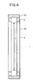
- Fig. 3 shows an oil track groove 4 of, for example, a fixed ring 32 integral with the fixed outer part and Fig. 4 shows a rotational ring 31 integral with the rotating inner part.
- the oil groove 4 is formed at the circumference of the fixed ring 32 and on the interior circumference of the rotational ring 31.
- the track shape of the oil groove 4 is not limited to a linear one along the circumference as shown in Fig. 3 and Fig. 4, and can be designed to have various shapes, such as a spiral, screw, or cross made by the intersection of two slanted/straight lines.
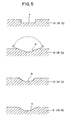
- the cross-sectional shape of the oil groove 4 can be formed to be substantially rectangular, substantially triangular, substantially arcuate, or a doubly arcuate shape in which an arcuate shape whose rotational centre is the inner part at both sides is combined with an arcuate shape whose rotational centre is the outer part therebetween. Accordingly, the cross-sectional shape is not limited to a specific shape.
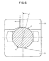
- Fig. 6, Fig. 7, and Fig. 8 show different views of a rotational ring 31 integral with a fixed ring 32, and each oil track groove 4 in a case where a spherical roller 34 is especially used as a roller.
- a spherical roller 34 of the ball bearing it is advisable to dispose the track oil groove 4 at a place other than the part where the spherical roller 34, the rotational ring 31, and the fixed ring 32 are rotated while contacting each other.
- a number based on the Dmn value is stored in the memory 61 that is below the Dmn value of each type of rotational device, and a signal to supply a lubricant is issued. Thereby, in most cases, the lubricant can be supplied to the rotational bearing 3 before lubrication of the bearing is necessary.
- a numerical value below the predetermined Dmn-related value corresponding to a rotation lifetime that has been newly calculated by actual use is stored in the memory 61 replacing the Dmn-related value based on past values, and a signal indicating that a lubricant should be newly supplied is issued on the basis of this new number.
- Fig. 1 shows an example in which an NC controller 6, including a memory 61 that stores a set number of revolutions, is provided for each individual main rotational shaft.
- the controller 6 including the memory 61 is not necessarily required to be disposed on the rotational device.
- the controller 6 including the memory 61 is not necessarily required to be disposed on the rotational device.
- a second embodiment has one memory 61 provided for a plurality of rotational devices in this way. This structure makes it possible to realize efficient design and control.
- a lubricant can be sequentially supplied without waiting for lubrication of the rotational bearing to become necessary.
- an accident due to the wear of a rotational bearing can be prevented, and the rotational bearing can be safely operated for a long time.
- the present invention is versatile and advantageous in operation.
Landscapes
- Engineering & Computer Science (AREA)
- General Engineering & Computer Science (AREA)
- Mechanical Engineering (AREA)
- Rolling Contact Bearings (AREA)
Claims (10)
- Umdrehungsvorrichtung, umfassend:einen inneren Teil (1) und einen äußeren Teil (2), von denen einer relativ zu dem anderen drehbar ist;ein oder mehrere Hauptrotationslager (3), die zwischen dem inneren Teil (1) und dem äußeren Teil (2) angeordnet sind;eine Steuerung (6) für die Schmiermittelzufuhr, die einen Speicher (61) beinhaltet, der die Anzahl an Umdrehungen speichert, die von dem oder jedem Lager durchgeführt werden und eine vorbestimmte Anzahl an Umdrehungen, die erforderlich ist zwischen aufeinanderfolgenden Schmierungen des oder jedes Rotationslagers (3) und ein Signal liefert, das die Schmierung eines Lagers einleitet, wenn die Anzahl an Umdrehungen, die nach einer Schmierung durchgeführt und in dem Speicher (61) gespeichert wurden, die vorbestimmte Anzahl an Umdrehungen für das Lager erreicht hat.
- Umdrehungsvorrichtung nach Anspruch 1, bei welcher das Schmiermittel automatisch basierend auf dem von der Steuerung (6) abgegebenen Schmiersignal zugeführt wird.
- Umdrehungsvorrichtung nach Anspruch 1, bei welcher der Speicher (61) die vorbestimmte Anzahl an Umdrehungen aktualisiert, falls die tatsächlich erforderliche Zeit zwischen Schmierungen kürzer ist als diejenige, die vorgeschlagen wird durch die in dem Speicher (61) gespeicherte vorbestimmte Anzahl an Umdrehungen.
- Umdrehungsvorrichtung nach Anspruch 1, bei welcher ein Speicher (61) für mehrere Umdrehungsvorrichtungen vorgesehen ist und die Rotationswerte mehrerer Rotationslager (3) in dem Speicher (61) gespeichert sind.
- Umdrehungsvorrichtung nach Anspruch 1, bei welcher der innere Teil (1) und der äußere Teil (2) jeweils komplementäre Ölführungsrillen (4) zur Aufnahme des Schmiermittels haben.
- Umdrehungsvorrichtung nach Anspruch 5, bei welcher die Ölführungsrillen (4) eine Querschnittsausgestaltung haben, die entweder im wesentlichen rechteckig, dreieckig oder gekrümmt ist.
- Umdrehungsvorrichtung nach Anspruch 1, bei welcher die Ölführungsrillen (4) eine kreisförmige Ausgestaltung haben.
- Umdrehungsvorrichtung nach Anspruch 1, bei welcher die inneren und äußeren Teile (1, 2) Lageraussparungen haben, um darin das Lager aufzunehmen und die Ölführungsrillen (4) versetzt zu Positionen angeordnet sind, wo das Lager die Lageraussparungen der inneren und äußeren Teile (1, 2) kontaktiert.
- Umdrehungsvorrichtung nach Anspruch 8, des weiteren umfassend eine Bohrung zum Zuführen von Schmiermittel in dem inneren Teil (1) und/oder dem äußeren Teil (2), um das Schmiermittel dem Lager (3) zuzuführen.
- Umdrehungsvorrichtung nach Anspruch 1, bei welcher das Lager (3) eine sphärische Kugel (34) ist.
Applications Claiming Priority (3)
| Application Number | Priority Date | Filing Date | Title |
|---|---|---|---|
| JP2001220065 | 2001-07-19 | ||
| JP2001220065A JP2003028173A (ja) | 2001-07-19 | 2001-07-19 | 回転部支持体 |
| CA002366284A CA2366284A1 (en) | 2001-07-19 | 2001-12-27 | Rotational-part supporter |
Publications (2)
| Publication Number | Publication Date |
|---|---|
| EP1277977A1 EP1277977A1 (de) | 2003-01-22 |
| EP1277977B1 true EP1277977B1 (de) | 2006-08-09 |
Family
ID=32108582
Family Applications (1)
| Application Number | Title | Priority Date | Filing Date |
|---|---|---|---|
| EP02100569A Revoked EP1277977B1 (de) | 2001-07-19 | 2002-05-28 | Umdrehungsvorrichtung |
Country Status (4)
| Country | Link |
|---|---|
| US (1) | US20030015374A1 (de) |
| EP (1) | EP1277977B1 (de) |
| JP (1) | JP2003028173A (de) |
| CA (2) | CA2366284A1 (de) |
Cited By (4)
| Publication number | Priority date | Publication date | Assignee | Title |
|---|---|---|---|---|
| US9551460B2 (en) | 2014-12-23 | 2017-01-24 | Lincoln Industrial Corporation | Bearing system with lubrication controller |
| US9695979B2 (en) | 2014-12-23 | 2017-07-04 | Lincoln Industrial Corporation | Method of controlling bearing lubrication system |
| US9810372B2 (en) | 2014-12-31 | 2017-11-07 | Lincoln Industrial Coporation | Bearing system with lubricated exclusion seal |
| US9841141B2 (en) | 2014-12-31 | 2017-12-12 | Lincoln Industrial Corporation | Lubrication method for housing having an exclusion seal |
Families Citing this family (6)
| Publication number | Priority date | Publication date | Assignee | Title |
|---|---|---|---|---|
| JP2003042392A (ja) † | 2001-07-27 | 2003-02-13 | I M N Kk | 回転部支持体における潤滑油供給方法 |
| JP5299074B2 (ja) * | 2009-05-13 | 2013-09-25 | パナソニック株式会社 | モータと発電機と送風装置と風力発電装置 |
| DE112010003390T5 (de) * | 2009-08-27 | 2012-12-06 | Aktiebolaget Skf | Verfahren und System zum Ermitteln und Ausführen korrekter automatischer Nachschmierung für eine Anzahl von Lagern |
| JP5462237B2 (ja) * | 2011-12-12 | 2014-04-02 | 株式会社日本製鋼所 | 射出成形機の給脂方法 |
| WO2017007358A1 (en) * | 2015-07-06 | 2017-01-12 | S.C. Rulmenti S.A. | Rolling bearing with lubrication grooves in the raceways |
| CN120798957A (zh) * | 2025-07-15 | 2025-10-17 | 浙江丰波机电科技有限公司 | 一种高润滑性轮毂轴承及工艺 |
Family Cites Families (12)
| Publication number | Priority date | Publication date | Assignee | Title |
|---|---|---|---|---|
| US1356444A (en) * | 1919-07-28 | 1920-10-19 | Golden Asher | Ball-bearing |
| US4039231A (en) * | 1976-03-12 | 1977-08-02 | Yale Engineering Company | Ball bearing assembly |
| DE8516167U1 (de) * | 1985-06-03 | 1985-07-25 | Pfaff Industriemaschinen Gmbh, 6750 Kaiserslautern | Schmiervorrichtung für die Laufbahn eines Umlauf-Steppstichgreifers einer Näh- oder Stickmaschine |
| JP2511112B2 (ja) * | 1988-07-12 | 1996-06-26 | 日本トムソン株式会社 | 蓋付き旋回輪軸受の潤滑装置 |
| JP2537089B2 (ja) * | 1989-08-22 | 1996-09-25 | ファナック株式会社 | 射出成形機の自動給脂方法 |
| EP0458499B1 (de) * | 1990-05-21 | 1997-07-23 | Makino Milling Machine Co. Ltd. | Kühlapparat eines Maschinenspindellagers |
| EP0854314B1 (de) * | 1993-03-18 | 2003-08-20 | B a r m a g AG | Verfahren zur Zuführung von Schmiermittel an ein Wälzlager |
| JP3114438B2 (ja) * | 1993-06-25 | 2000-12-04 | 日本精工株式会社 | 転がり軸受 |
| US5381874A (en) * | 1993-10-15 | 1995-01-17 | Caterpillar Inc. | Automatic lubrication control |
| US6010420A (en) * | 1995-08-21 | 2000-01-04 | Ntn Corporation | Pulley, ball bearing and fan for preventing the occurence of abnormal noise under cold ambient conditions |
| FR2740187B1 (fr) * | 1995-10-18 | 1997-11-21 | Snecma | Roulement avec drainage dynamique alimente en lubrifiant |
| NL1014210C2 (nl) * | 2000-01-27 | 2001-07-30 | Skf Eng & Res Centre Bv | Intelligent lageronderhoud. |
-
2001
- 2001-07-19 JP JP2001220065A patent/JP2003028173A/ja active Pending
- 2001-12-27 CA CA002366284A patent/CA2366284A1/en not_active Abandoned
-
2002
- 2002-03-27 US US10/107,791 patent/US20030015374A1/en not_active Abandoned
- 2002-05-28 EP EP02100569A patent/EP1277977B1/de not_active Revoked
- 2002-07-19 CA CA002394480A patent/CA2394480C/en not_active Expired - Lifetime
Cited By (4)
| Publication number | Priority date | Publication date | Assignee | Title |
|---|---|---|---|---|
| US9551460B2 (en) | 2014-12-23 | 2017-01-24 | Lincoln Industrial Corporation | Bearing system with lubrication controller |
| US9695979B2 (en) | 2014-12-23 | 2017-07-04 | Lincoln Industrial Corporation | Method of controlling bearing lubrication system |
| US9810372B2 (en) | 2014-12-31 | 2017-11-07 | Lincoln Industrial Coporation | Bearing system with lubricated exclusion seal |
| US9841141B2 (en) | 2014-12-31 | 2017-12-12 | Lincoln Industrial Corporation | Lubrication method for housing having an exclusion seal |
Also Published As
| Publication number | Publication date |
|---|---|
| JP2003028173A (ja) | 2003-01-29 |
| CA2366284A1 (en) | 2003-06-27 |
| US20030015374A1 (en) | 2003-01-23 |
| EP1277977A1 (de) | 2003-01-22 |
| CA2394480C (en) | 2006-04-18 |
| CA2394480A1 (en) | 2003-01-19 |
Similar Documents
| Publication | Publication Date | Title |
|---|---|---|
| EP1471275B1 (de) | Rollenlager und Schmiermethode dafür | |
| EP1277977B1 (de) | Umdrehungsvorrichtung | |
| EP1850020B1 (de) | Wälzlagervorrichtung | |
| JP5205391B2 (ja) | 風力タービンのピッチブレードの軸受を動的に潤滑する方法 | |
| EP0288941A2 (de) | Schmieranlage mit geregelter Auffüllung | |
| EP2071203A2 (de) | Wälzkörperlager und Wälzkörperlageranordnung | |
| CN102472685A (zh) | 用于确定利用电磁轴承的涡轮机械的机械备用轴承的间隙的装置和方法 | |
| US6276836B1 (en) | Cage for radial ball bearing | |
| EP1850019A1 (de) | Kugellagervorrichtung und drehvorrichtung | |
| US20060291759A1 (en) | Cylindrical roller bearing | |
| JP2001263292A (ja) | 磁気軸受真空ポンプの制振システムと軸受センタリング装置 | |
| EP0289610A1 (de) | Lager für hochgeschwindigkeitsmotor | |
| JP2006125540A (ja) | 転がり軸受装置およびスピンドル | |
| CN101107454A (zh) | 滚动轴承装置和旋转设备 | |
| US8529134B2 (en) | Rolling bearing apparatus | |
| CN116336083A (zh) | 一种外圈滚道带润滑小孔的高速轴承、直接微量供脂润滑系统 | |
| JP2002339960A (ja) | 転がり軸受装置 | |
| WO1991014874A1 (en) | Journal bearing with high stiffness | |
| EP0426279B1 (de) | Hohlrollenlager und sein Herstellungs- und Montageverfahren | |
| KR960006620B1 (ko) | 고정밀도 스웨이징 방법 및 스웨이징 장치 | |
| EP3627134B1 (de) | Verfahren zur erfassung einer beschädigung in einem lager | |
| JP2008032090A (ja) | 軸受給油装置および風力発電機の回転軸支持構造 | |
| JP4322641B2 (ja) | 円筒ころ軸受 | |
| US11226005B2 (en) | Bearing arrangements, and module carrier for them | |
| JP2008261357A (ja) | 風力発電機の回転軸支持構造 |
Legal Events
| Date | Code | Title | Description |
|---|---|---|---|
| PUAI | Public reference made under article 153(3) epc to a published international application that has entered the european phase |
Free format text: ORIGINAL CODE: 0009012 |
|
| AK | Designated contracting states |
Kind code of ref document: A1 Designated state(s): AT BE CH CY DE DK ES FI FR GB GR IE IT LI LU MC NL PT SE TR |
|
| AX | Request for extension of the european patent |
Free format text: AL;LT;LV;MK;RO;SI |
|
| 17P | Request for examination filed |
Effective date: 20030708 |
|
| AKX | Designation fees paid |
Designated state(s): DE FR GB IT |
|
| GRAP | Despatch of communication of intention to grant a patent |
Free format text: ORIGINAL CODE: EPIDOSNIGR1 |
|
| GRAS | Grant fee paid |
Free format text: ORIGINAL CODE: EPIDOSNIGR3 |
|
| GRAA | (expected) grant |
Free format text: ORIGINAL CODE: 0009210 |
|
| AK | Designated contracting states |
Kind code of ref document: B1 Designated state(s): DE FR GB IT |
|
| PG25 | Lapsed in a contracting state [announced via postgrant information from national office to epo] |
Ref country code: IT Free format text: LAPSE BECAUSE OF FAILURE TO SUBMIT A TRANSLATION OF THE DESCRIPTION OR TO PAY THE FEE WITHIN THE PRESCRIBED TIME-LIMIT;WARNING: LAPSES OF ITALIAN PATENTS WITH EFFECTIVE DATE BEFORE 2007 MAY HAVE OCCURRED AT ANY TIME BEFORE 2007. THE CORRECT EFFECTIVE DATE MAY BE DIFFERENT FROM THE ONE RECORDED. Effective date: 20060809 |
|
| REG | Reference to a national code |
Ref country code: GB Ref legal event code: FG4D |
|
| REF | Corresponds to: |
Ref document number: 60213727 Country of ref document: DE Date of ref document: 20060921 Kind code of ref document: P |
|
| ET | Fr: translation filed | ||
| PLBI | Opposition filed |
Free format text: ORIGINAL CODE: 0009260 |
|
| PLAX | Notice of opposition and request to file observation + time limit sent |
Free format text: ORIGINAL CODE: EPIDOSNOBS2 |
|
| 26 | Opposition filed |
Opponent name: KIENINGER TECHNOLOGIE GMBH Effective date: 20070508 |
|
| PLAF | Information modified related to communication of a notice of opposition and request to file observations + time limit |
Free format text: ORIGINAL CODE: EPIDOSCOBS2 |
|
| PLBB | Reply of patent proprietor to notice(s) of opposition received |
Free format text: ORIGINAL CODE: EPIDOSNOBS3 |
|
| PLAY | Examination report in opposition despatched + time limit |
Free format text: ORIGINAL CODE: EPIDOSNORE2 |
|
| PLAH | Information related to despatch of examination report in opposition + time limit modified |
Free format text: ORIGINAL CODE: EPIDOSCORE2 |
|
| PLBC | Reply to examination report in opposition received |
Free format text: ORIGINAL CODE: EPIDOSNORE3 |
|
| RDAF | Communication despatched that patent is revoked |
Free format text: ORIGINAL CODE: EPIDOSNREV1 |
|
| APAH | Appeal reference modified |
Free format text: ORIGINAL CODE: EPIDOSCREFNO |
|
| APBM | Appeal reference recorded |
Free format text: ORIGINAL CODE: EPIDOSNREFNO |
|
| APBP | Date of receipt of notice of appeal recorded |
Free format text: ORIGINAL CODE: EPIDOSNNOA2O |
|
| APBQ | Date of receipt of statement of grounds of appeal recorded |
Free format text: ORIGINAL CODE: EPIDOSNNOA3O |
|
| PLAB | Opposition data, opponent's data or that of the opponent's representative modified |
Free format text: ORIGINAL CODE: 0009299OPPO |
|
| REG | Reference to a national code |
Ref country code: DE Ref legal event code: R064 Ref document number: 60213727 Country of ref document: DE Ref country code: DE Ref legal event code: R103 Ref document number: 60213727 Country of ref document: DE |
|
| APBU | Appeal procedure closed |
Free format text: ORIGINAL CODE: EPIDOSNNOA9O |
|
| RDAG | Patent revoked |
Free format text: ORIGINAL CODE: 0009271 |
|
| STAA | Information on the status of an ep patent application or granted ep patent |
Free format text: STATUS: PATENT REVOKED |
|
| 27W | Patent revoked |
Effective date: 20110407 |
|
| GBPR | Gb: patent revoked under art. 102 of the ep convention designating the uk as contracting state |
Effective date: 20110407 |
|
| PGFP | Annual fee paid to national office [announced via postgrant information from national office to epo] |
Ref country code: FR Payment date: 20110523 Year of fee payment: 10 |
|
| PGFP | Annual fee paid to national office [announced via postgrant information from national office to epo] |
Ref country code: GB Payment date: 20110525 Year of fee payment: 10 |
|
| REG | Reference to a national code |
Ref country code: DE Ref legal event code: R107 Ref document number: 60213727 Country of ref document: DE Effective date: 20110908 |
|
| PGFP | Annual fee paid to national office [announced via postgrant information from national office to epo] |
Ref country code: IT Payment date: 20110523 Year of fee payment: 10 Ref country code: DE Payment date: 20110525 Year of fee payment: 10 |