EP1275533A2 - Anhängerkupplung - Google Patents
Anhängerkupplung Download PDFInfo
- Publication number
- EP1275533A2 EP1275533A2 EP02009190A EP02009190A EP1275533A2 EP 1275533 A2 EP1275533 A2 EP 1275533A2 EP 02009190 A EP02009190 A EP 02009190A EP 02009190 A EP02009190 A EP 02009190A EP 1275533 A2 EP1275533 A2 EP 1275533A2
- Authority
- EP
- European Patent Office
- Prior art keywords
- rest position
- working position
- bolt
- trailer coupling
- locking
- Prior art date
- Legal status (The legal status is an assumption and is not a legal conclusion. Google has not performed a legal analysis and makes no representation as to the accuracy of the status listed.)
- Granted
Links
Images


Classifications
-
- B—PERFORMING OPERATIONS; TRANSPORTING
- B60—VEHICLES IN GENERAL
- B60D—VEHICLE CONNECTIONS
- B60D1/00—Traction couplings; Hitches; Draw-gear; Towing devices
- B60D1/01—Traction couplings or hitches characterised by their type
- B60D1/06—Ball-and-socket hitches, e.g. constructional details, auxiliary devices, their arrangement on the vehicle
-
- B—PERFORMING OPERATIONS; TRANSPORTING
- B60—VEHICLES IN GENERAL
- B60D—VEHICLE CONNECTIONS
- B60D1/00—Traction couplings; Hitches; Draw-gear; Towing devices
- B60D1/48—Traction couplings; Hitches; Draw-gear; Towing devices characterised by the mounting
- B60D1/54—Traction couplings; Hitches; Draw-gear; Towing devices characterised by the mounting collapsible or retractable when not in use, e.g. hide-away hitches
Definitions
- the invention relates to a trailer coupling for motor vehicles, especially passenger cars, with a coupling arm, at its free end a head piece for detachable attachment of a trailer carries and between one in the vehicle assembled state rear-facing working position and one located further forward under the vehicle Rest position adjustable by performing a diving movement is, and with a locking device for locking the Coupling arm in the rest position.
- Such a trailer hitch is for example in the DE OS 26 19 913 shown.
- the advantage of such a towbar is that they are at rest in one The area below the vehicle disappears and so to speak is therefore stowed aesthetically on the one hand and change the function of a bumper of the vehicle.
- the known trailer hitch In the rest position, the known trailer hitch be secured by a locking device, according to DE OS 26 19 913 for example by a spring.
- the disadvantage is that the known trailer coupling for a user only cumbersome and inconvenient to handle manually is.
- the clutch arm is in the rest position from the rear mostly not visible, so it can only be felt by touching it soiling the user's hands, or by looking under the vehicle, for which the user is under the vehicle must bend, can be located.
- the user must be way below grasp the vehicle, which is why he usually under the vehicle must crawl to grab the clutch arm and out of the Bring the rest position into the working position.
- the clutch arm be at rest is acted upon by a force, so that after it releasing the locking device automatically from the rest position towards the working position in a lower intermediate position pivots so that it is conveniently accessible to a user and can be brought into the working position.
- the lower intermediate position is a provision position, so to speak where the coupling arm, for example, below a bumper of the vehicle hangs down and can be easily grasped by the user. This must be just bend down slightly to grab the clutch arm.
- the construction according to the invention is robust and largely insensitive to dirt, so that an open structure underneath the vehicle is easily possible.
- a supporting structure for the trailer coupling according to the invention can serve a common cross member, as it also for Rigid towbars that cannot be brought into the rest position Is used.
- An adaptation to different types of cars and thus varying space conditions is easy possible.
- the one acting on the clutch arm in the rest position Force can advantageously serve its weight. It is also possible that the force in whole or in part from one Provisioning spring arrangement is provided, for example by a spring which is in the rest position of the Clutch arm on the one hand on the vehicle and on the other hand on the clutch arm supports and which is preloaded by the clutch arm is brought to rest.
- the coupling arm is preferably by a holding device held in the working position.
- a reset device in particular a return spring arrangement, represents the Coupling arm after releasing the holding device from the working position back to the rest position. It is through the clutch arm on the way from the rest position to the working position biased. Also for returning the clutch arm in the rest position must therefore be a user of the trailer hitch do not reach under the vehicle. In principle it is also conceivable that the user, so to speak, the coupling arm Gives momentum to him from the working position to the rest position bring to. The reset device would then not necessarily be required.
- the reset device can in principle on the whole Prestressed way between rest position and working position become. However, it is expediently only or at least essentially on the way from the intermediate position biased into the working position so that the Swiveling the coupling arm from the rest position into the intermediate position not hindered by the reset device becomes.
- the reset device is expedient dimensioned so that by moving the clutch arm brought into the working position in the reset device Energy for moving the clutch arm back in the rest position is sufficient after releasing the holding device.
- the holding device and the locking device each be separate devices.
- the holding device and the locking device are formed by a locking device so that a single device performs the functions of the clutch arm holding device holding in the working position and the locking device which detects this in the rest position Fulfills.
- the locking device preferably contains one with the coupling arm pivotally connected locking plate on the a rest position recess assigned to the rest position and a work position recess associated with a work position are arranged at an angular distance from each other.
- the recesses is a vehicle-fixed, in any position automatically engages in the relevant recess Tie assigned.
- a slideway is provided on which the bolt when turning the Lock washer between work position and rest position spring-loaded is applied.
- the latch snaps then automatically into the recess in question.
- the entry length of the bolt into the working position recess is advantageous smaller than the entry length of the Latch into the rest position recess.
- the bolt is after loosening from the working position recess when turning the Lock washer operated by the slide and around that Proportion of the for releasing the bolt from the rest position recess required actuation strokes raised by this Actuation stroke is greater than the actuation stroke for releasing the bolt from the working position recess.
- the locking device and / or the holding device or expediently the locking device forming both devices is advantageous by a from the interior of the Vehicle out and / or in the area of the rear vehicle contour operable actuating device releasable.
- the actuator can for example a relay or another contain electromagnetic actuator, which or by a electrical switches arranged in the interior of the vehicle is operable.
- the actuating device has one in the assembled state of the towbar in Area of the rear vehicle contour, especially below a vehicle bumper, or in the luggage compartment of the vehicle arranged control lever.
- the actuating device is preferably assigned to the bolt.
- the bolt is expediently from the actuating device can be lifted off so that it is particularly useful when actuated through the slideway arranged on the locking disk from the Actuator can lift off.
- the actuator preferably includes one on the Bolt-acting deflection gear, especially a roller gear, around the actuating forces exerted on the actuating device transfer to the bolt and redirect.
- the actuating device can thus be arranged ergonomically and be designed.
- the actuator is advantageously an elastic Brake device assigned by the actuator biased when releasing the locking device is, so that the actuation of the actuator when Release the locking device or the locking device against a counterforce exerted by the braking device he follows.
- Arrows 13, 14 point backwards to the rear or forwards to the front of the Vehicle 11.
- the trailer coupling 10 can be detachably attached to a trailer be when the coupling arm 15 in the in the figures 1C, 2C shown working position, in which the head piece 17 is directed upwards. From the working position the coupling arm 15 can be in a rest position (see figures 1A, 2A) while performing a diving movement around the not illustrated rear apron or the like of the vehicle around be pivoted, in which the head piece 17 one down describes directed partial circular path.
- the coupling arm 15 is arranged on a pivot axis 16.
- the pivot axis 16 is rotatable on bearing brackets 18, 19 stored, which are arranged on the cross member 12.
- the pivot axis 16 extends obliquely to the cross member 12, that is to say at a 90 ° angle deviating angle transversely to the vehicle longitudinal axis, so that the Coupling arm 15 in the swung-in state, in the rest position, as flat as possible on the vehicle floor or in a recess is in the lower region of the vehicle 11.
- the clutch arm 15 is stowed away to save space in the rest position, however difficult to grasp manually.
- the locking device 20 contains a locking disk 21, which is pivotally connected to the coupling arm 15 and is arranged coaxially to the pivot axis 16.
- the pivot axis 16 penetrates the locking disk 21 in the present case approximately in its Center.
- On the locking disk 21 are at an angular distance from each other a rest position recess assigned to the rest position 22 and a working position recess assigned to the working position 23 arranged.
- the angle of rotation of the clutch arm 11 between rest position and working position accordingly are the recesses 22, 23 at an angular distance of about 180 ° arranged to each other on the locking plate 21.
- the recesses 22, 23 extend from the outer circumference of the present in the Essentially circular locking disk 21 forth to the center out. Other arrangements of the recesses are straightforward conceivable, for example, they could be on the front of a Lock washer arranged.
- a bolt 24 engages in the recesses 22, 23 in the relevant Rest or work position.
- the latch 24 extends essentially parallel in its longitudinal direction to the pivot axis 16.
- the bolt 24 is on bearing brackets 25 pivotally mounted, the vehicle on the crossbar 12 are arranged.
- a bolt pivot axis 26 is on the bearing brackets 25 mounted and extends transversely to the pivot axis 16 of the coupling arm 15.
- One end of the latch 24 is between the bearing brackets 25 and is arranged by the bolt pivot axis 26 permeated.
- free end of the Bolt 24 is a locking portion 27, the in the recesses 22, 23 or swung out of these is.
- the bolt 24 is a safety device 28 in the Recesses 22, 23 secured in the rest or working position.
- the securing device 28 is operated by a spring 29 formed on the one hand on the bolt 24 and on the other hand fixed to the vehicle, is attached to the bearing bracket 19 in the present case.
- the supports 30, 31 take from the locking plate 21 or from the clutch arm 15 forces exerted on the bolt 24.
- the Support devices 30, 31 are fixed to the cross member 12 on the vehicle arranged and have recesses 32 into which the locking section 27 of the bolt 24 at least in the recesses 22, 23 engages pivoted state.
- Support device 30 is in the present case a separate one on the cross member 12 arranged support element is provided.
- a support device 31 serves the bearing bracket 19.
- the locking disk 21 is at least in the areas of their recesses 22, 23 between the support devices 30, 31 arranged. At rest the rest position recess 22 is aligned with the recesses 32, in the working position the working position recess 23, so that the latch in the relevant recesses can intervene at the same time.
- a locking pin which runs parallel to the pivot axis 16, in the recesses 22, 23 or in on the locking disc 21 engage recesses arranged on the face.
- a locking device could be provided that immediately engages on the coupling arm so that no locking washer would be required.
- the locking device 20 could be immediate operated by a user, for example by applying an appropriate unlocking force to the Bolt 24 exercises.
- an actuator for this 33 provided, their function in particular can be seen from the figure sequences 3A-3C and 4A-4C.
- FIG. 3A-3C and 4A-4C it should be noted that between the figures there are sometimes slight geometric deviations, in particular, dimensions and angles are shown differently and that some parts are not shown or only partially are, but overall on the principle of operation the actuator 33 has no effect Has.
- the actuating device 33 acts on the bolt 24.
- Sie contains a pivotally mounted on a pivot axis 34 Swivel element 35.
- the swivel axis 34 is fixed to the vehicle arranged on the cross member 12. It stands apart from this.
- the Pivot axis 34 extends transversely to the bolt pivot axis 26.
- Das Swivel element 35 is designed like a sleeve or tube and arranged rotatably on the pivot axis 34. From the swivel element 35 are radially an operating lever 36, a stop piece 37 and a roller axis 38, in the exemplary embodiment each with an angular distance from each other.
- a reset device 39 provides the actuating device 33 after actuation by a user in a Figures 3A, 4A shown basic position back.
- the reset device 39 here contains a spring 40, on the one hand on the swivel element 35 and on the other hand fixed to the vehicle, for example on a bearing bracket 25.
- the spring 40 is when unlocking the locking device 20 excited ( Figure 3C, 4C) and provides the actuator 33 then return to their basic position.
- the locking device 20 By pivoting the operating lever 36, the locking device 20 can be unlocked.
- a behind the vehicle 11 standing user pulls the operating lever 36 so to speak to itself, with a deflection gear 41 the actuating pivoting movement of the pivot element 35 into a pivoting movement of the latch 24 deflected.
- the deflection gear 41 in the present case a roller gear, includes one on the roller shaft 38 rotatably mounted roller 42 on a central area of the bolt 24 rolling runway 43 rolls. present The runway 43 runs obliquely on the bolt 24, so that with progressive pivoting movement of the control lever 36 in Unlocking direction of the bolt 24 always further from the recesses 22 or 23 is moved out.
- pivot axis 34 inclined with respect to the bolt pivot axis 26 can be so that the runway 43 is not necessarily oblique must run.
- gear or lever gear There are also other forms of reversing gear conceivable, for example with gear or lever gear.
- the braking device 44 contains a vehicle-fixed, in this case arranged on the bearing bracket 19, elastic buffer element 45 to which the stop piece 37 when unlocking the locking device 20 strikes.
- the stopper 37 just touches the buffer element 45 not yet or only slightly, with the latch 24 begins to move out of one of the recesses 22, 23.
- the braking device fulfills, so to speak Safety function.
- actuating device 33 a separate reset device 39 and a separate braking device 44 are provided are assigned different functions are.
- a reset device is provided, which also Functions as a braking device or vice versa.
- the spring 40 could have a correspondingly high spring constant exhibit.
- the coupling arm only comes in the lower intermediate position 15 with a reset device 46 in force from this to a further movement to the working position prevented.
- the reset device 46 includes one of the Pivot axis 16 penetrated coil spring 47.
- One end of the Spring 47 is supported on the vehicle, in this case on the bearing bracket 18, while the other end stops 48 forms for the coupling arm 15 with which the coupling arm 15 on the way between the lower intermediate position and the working position is in frictional contact.
- the stop 48 projects in front of the pivot axis 16 and extends essentially parallel to this. On the way section between the intermediate position and the working position the stop 48 includes the coupling arm 15 in a bow-like manner.
- the trailer coupling 10 can then be in the rest position bring very easy:
- the clutch arm 15 After moving the latch 24 from the working position recess 23 provides the reset device 46 the clutch arm 15 in the rest position back.
- the bolt 24 slides with its front locking section 27 on a on the locking disk 21 between the recesses 22 and 23 arranged slideway 49 and ultimately engages in the rest position recess 22.
- the trailer coupling 10 is then locked in the rest position.
- the slideway 49 is on the outer circumference of the locking disk 21 arranged. It falls with respect to the axis of rotation the locking disk 21, in the present case the pivot axis 16, to the working position recess 23 down (see Figures 2A to 2C).
- the slideway 49 has a relation to the axis of rotation the locking disc 21 has an eccentric course, although other courses are also possible.
- the latch 24 is when turning the locking disc 21 between working and Rest position actuated in the unlocking direction, present moved away from the pivot axis 16. Here, the latch 24 lifts from the actuator 33.
- the user of the tow bar 10 therefore feels no or almost no feedback of the bolt 24 on the operating lever 36 and the other the locking of the coupling arm 15 works in the rest position reliable even when the user is operating the control lever 36 holds and not in the basic operating position ( Figure 3A, 4A).
- this extends into the reset device 46 energy introduced when moving the coupling arm 15 in the working position to this after releasing the locking device 20 to move back to the rest position.
- a user it is also conceivable for a user to be additional The clutch arm, for example give a push.
- the reset device for the clutch arm could also in entire or almost entire area between the rest position and the working position in force engagement with the clutch arm stand, in which case it is expediently provided that the coupling arm against the restoring force of the restoring device from the rest position to a lower intermediate position is feasible.
- a locking device and / or as a holding device for example also serve a spring arrangement or clip.
Landscapes
- Engineering & Computer Science (AREA)
- Transportation (AREA)
- Mechanical Engineering (AREA)
- Braking Elements And Transmission Devices (AREA)
- Agricultural Machines (AREA)
- Lock And Its Accessories (AREA)
- Handcart (AREA)
- Medicines Containing Plant Substances (AREA)
- Fuel Cell (AREA)
Abstract
Description
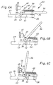
- Figur 1A
- eine an einem Querholm eines Fahrzeugs montierte erfindungsgemäße Anhängerkupplung mit einem in Ruhestellung befindlichen Kupplungsarm in einer Ansicht von schräg hinten unten (bezogen auf das Fahrzeug),
- Figur 1B
- die Anhängerkupplung gemäß Figur 1A, wobei jedoch der Kupplungsarm eine untere Zwischenstellung einnimmt,
- Figur 1C
- die Anhängerkupplung gemäß Figuren 1A, 1B, wobei der Kupplungsarm eine Arbeitsstellung einnimmt,
- Figur 2A
- die Anhängerkupplung gemäß Figur 1A etwa in Seitenansicht gemäß Pfeil IIA, wobei lediglich der Kupplungsarm und Teile einer Verriegelungsvorrichtung sowie Teile einer Rückstellvorrichtung gezeigt sind,
- Figur 2B, 2C
- die Ansicht gemäß Figur 2A, wobei sich jedoch der Kupplungsarm in der unteren Zwischenstellung bzw. in der Arbeitsstellung befindet (siehe Figuren 1B bzw. 1C),
- Figuren 3A-3C
- eine Betätigungseinrichtung der Anhängerkupplung gemäß den Figuren 1 und 2 in seitlicher Ansicht, wobei ein Betätigungsablauf der Betätigungseinrichtung dargestellt ist, und die
- Figuren 4A-4C
- die Betätigungseinrichtung gemäß den Figuren 3A bis 3C in einer teilweise schematisierten Ansicht von oben.
Claims (17)
- Anhängerkupplung für Kraftfahrzeuge, insbesondere Personenkraftwagen, mit einem Kupplungsarm (15), der an seinem freien Ende ein Kopfstück (17) zum lösbaren Befestigen eines Anhängers trägt und zwischen einer im am Fahrzeug (11) montierten Zustand nach hinten gerichteten Arbeitsstellung und einer weiter vorne unter dem Fahrzeug (11) angeordneten Ruhestellung unter Ausführung einer Tauchbewegung verstellbar ist, und mit einer Feststellvorrichtung zum Feststellen des Kupplungsarms (15) in Ruhestellung, dadurch gekennzeichnet, dass der Kupplungsarm (15) in der Ruhestellung durch eine Kraft beaufschlagt ist, so dass er nach dem Lösen der Feststellvorrichtung selbsttätig aus der Ruhestellung zur Arbeitsstellung hin in eine untere Zwischenstellung schwenkt, so dass er von einem Benutzer bequem ergreifbar und in die Arbeitsstellung bringbar ist.
- Anhängerkupplung nach Anspruch 1, dadurch gekennzeichnet, dass der Kupplungsarm (15) durch eine Haltevorrichtung in der Arbeitsstellung gehalten wird, und dass eine Rückstellvorrichtung (46), insbesondere eine Rückstellfederanordnung (47), vorgesehen ist, die den Kupplungsarm (15) nach Lösen der Haltevorrichtung aus der Arbeitsstellung in die Ruhestellung zurückstellt und die durch den Kupplungsarm (15) auf dem Weg von der Ruhestellung in die Arbeitsstellung vorgespannt wird.
- Anhängerkupplung nach Anspruch 2, dadurch gekennzeichnet, dass die Rückstellvorrichtung (46) ausschließlich oder zumindest im Wesentlichen auf dem Wegabschnitt von der Zwischenstellung in die Arbeitsstellung vorgespannt wird.
- Anhängerkupplung nach Anspruch 2 oder 3, dadurch gekennzeichnet, dass der Kupplungsarm (15) mit der Rückstellvorrichtung (46) nur auf dem Wegabschnitt in Krafteingriff steht, der sich zwischen der Arbeitsstellung und etwa dem Bereich der Zwischenstellung erstreckt.
- Anhängerkupplung nach einem der Ansprüche 2 bis 4, dadurch gekennzeichnet, dass die Rückstellvorrichtung (46) derart dimensioniert ist, dass die durch Bewegen des Kupplungsarms (15) in die Arbeitsstellung in die Rückstellvorrichtung (46) eingebrachte Energie für das Zurückbewegen des Kupplungsarms (15) in die Ruhestellung nach Lösen der Haltevorrichtung ausreicht.
- Anhängerkupplung nach einem der vorhergehenden Ansprüche, dadurch gekennzeichnet, dass als die den Kupplungsarm (15) in Ruhestellung beaufschlagende Kraft dessen Gewichtskraft und/oder eine von einer Bereitstellungs-Federanordnung bereitgestellte Bereitstellungskraft vorgesehen ist.
- Anhängerkupplung nach einem der vorhergehenden Ansprüche, dadurch gekennzeichnet, dass die Haltevorrichtung und die Feststellvorrichtung von einer Verriegelungsvorrichtung (24) (20) gebildet werden.
- Anhängerkupplung nach Anspruch 7, dadurch gekennzeichnet, dass die Verriegelungsvorrichtung (20) eine mit dem Kupplungsarm (15) schwenkfest verbundene Riegelscheibe (21) enthält, an der eine der Ruhestellung zugeordnete Ruhestellungs-Ausnehmung (22) und eine der Arbeitsstellung zugeordnete Arbeitsstellungs-Ausnehmung (23) mit Winkelabstand zueinander angeordnet sind, denen ein fahrzeugfest anzuordnender, in jeder Stellung selbsttätig in die betreffende Ausnehmung (22, 23) einrastender Riegel (24) zugeordnet ist.
- Anhängerkupplung nach Anspruch 7 oder 8, dadurch gekennzeichnet, dass an der Riegelscheibe (21) zwischen der Arbeitsstellungs-Ausnehmung (23) und der Ruhestellungs-Ausnehmung (22) eine Gleitbahn (49) vorgesehen ist, auf der der Riegel (24) beim Drehen der Riegelscheibe (21) zwischen Arbeitsstellung und Ruhestellung federbelastet anliegt.
- Anhängerkupplung nach Anspruch 9, dadurch gekennzeichnet, dass die Eintrittslänge des Riegels (24) in die Arbeitsstellungs-Ausnehmung (23) kleiner ist als die Eintrittslänge des Riegels (24) in die Ruhestellungs-Ausnehmung (22), so dass der Riegel (24) nach dem Lösen aus der Arbeitsstellungs-Ausnehmung (23) beim Drehen der Riegelscheibe (21) von der Gleitbahn (49) betätigbar ist und dabei derjenige Anteil des zum Lösen des Riegels (24) aus der Ruhestellungs-Ausnehmung (22) erforderlichen Betätigungshubs erbringbar ist, um den dieser Betätigungshub größer ist als der Betätigungshub zum Lösen des Riegels (24) aus der Arbeitsstellungs-Ausnehmung (23).
- Anhängerkupplung nach einem der vorhergehenden Ansprüche, dadurch gekennzeichnet, dass die Feststellvorrichtung und/oder die Haltevorrichtung durch eine vom Innenraum des Fahrzeugs (11) aus und/oder im Bereich der hinteren Fahrzeugkontur bedienbare Betätigungseinrichtung (33) lösbar ist.
- Anhängerkupplung nach Anspruch 11, dadurch gekennzeichnet, dass die Betätigungseinrichtung (33) einen im montierten Zustand der Anhängerkupplung im Bereich der hinteren Fahrzeugkontur, insbesondere unterhalb eines Fahrzeug (11)-Stoßfängers, oder im Gepäckraum des Fahrzeuges (11) angeordneten Bedienhebel (36) aufweist.
- Anhängerkupplung nach Anspruch 11 oder 12, dadurch gekennzeichnet, dass die Betätigungseinrichtung (33) dem Riegel (24) zugeordnet ist.
- Anhängerkupplung nach Anspruch 13, dadurch gekennzeichnet, dass der Riegel (24) von der Betätigungseinrichtung (33) abhebbar ist.
- Anhängerkupplung nach Anspruch 13 oder 14, dadurch gekennzeichnet, dass die Betätigungseinrichtung (33) ein auf den Riegel (24) wirkendes Umlenkgetriebe (41), insbesondere ein Rollengetriebe (38, 42, 43), aufweist.
- Anhängerkupplung nach einem der Ansprüche 11 bis 15, dadurch gekennzeichnet, dass der Betätigungseinrichtung (33) eine elastische Bremsvorrichtung (44) zugeordnet ist, die durch die Betätigungseinrichtung (33) beim Lösen der Feststellvorrichtung vorgespannt wird, so dass das Betätigen der Betätigungseinrichtung (33) beim Lösen der Verriegelungsvorrichtung (20) gegen eine von der Bremsvorrichtung ausgeübte Gegenkraft erfolgt.
- Fahrzeug, insbesondere Personenkraftwagen, mit einer Anhängerkupplung (10) nach einem der vorhergehenden Ansprüche.
Applications Claiming Priority (2)
| Application Number | Priority Date | Filing Date | Title |
|---|---|---|---|
| DE10134318A DE10134318A1 (de) | 2001-07-14 | 2001-07-14 | Anhängerkupplung |
| DE10134318 | 2001-07-14 |
Publications (4)
| Publication Number | Publication Date |
|---|---|
| EP1275533A2 true EP1275533A2 (de) | 2003-01-15 |
| EP1275533A3 EP1275533A3 (de) | 2004-07-28 |
| EP1275533B1 EP1275533B1 (de) | 2006-08-09 |
| EP1275533B2 EP1275533B2 (de) | 2013-08-28 |
Family
ID=7691814
Family Applications (1)
| Application Number | Title | Priority Date | Filing Date |
|---|---|---|---|
| EP02009190.6A Expired - Lifetime EP1275533B2 (de) | 2001-07-14 | 2002-04-25 | Anhängerkupplung |
Country Status (3)
| Country | Link |
|---|---|
| EP (1) | EP1275533B2 (de) |
| AT (1) | ATE335623T1 (de) |
| DE (2) | DE10134318A1 (de) |
Cited By (7)
| Publication number | Priority date | Publication date | Assignee | Title |
|---|---|---|---|---|
| EP1512558A1 (de) * | 2003-09-02 | 2005-03-09 | Westfalia Automotive GmbH & Co. KG | Anhängerkupplung für Kraftfahrzeuge |
| EP1557298A1 (de) * | 2004-01-22 | 2005-07-27 | ORIS FAHRZEUGTEILE HANS RIEHLE GmbH | Anhängekupplung |
| EP1717067A1 (de) * | 2005-04-26 | 2006-11-02 | Jaeger Cartronix GmbH | Antrieb für eine Anhängerkupplung |
| EP1782973A3 (de) * | 2005-11-03 | 2007-06-13 | Scambia Industrial Developments Aktiengesellschaft | Betätigungseinrichtung |
| EP2412550A1 (de) * | 2010-07-31 | 2012-02-01 | WESTFALIA - Automotive GmbH | Anhängekupplung |
| EP2266820B2 (de) † | 2006-07-29 | 2019-10-02 | Bosal ACPS Holding 2 B.V. | Anhängekupplung |
| WO2022096377A3 (de) * | 2020-11-03 | 2022-07-14 | Westfalia-Automotive Gmbh | Anhängekupplung mit einer fixiereinrichtung |
Families Citing this family (4)
| Publication number | Priority date | Publication date | Assignee | Title |
|---|---|---|---|---|
| EP1634730A1 (de) | 2004-09-14 | 2006-03-15 | MVG Metallverarbeitungsgesellschaft mbH | Anhängerkupplung mit Kugelgelenk |
| DE102004044912A1 (de) * | 2004-09-14 | 2006-03-30 | Mvg Metallverarbeitungsgesellschaft Mbh | Anhängekupplung mit Kugelgelenk |
| DE102009046631A1 (de) | 2009-11-11 | 2011-05-12 | Zf Friedrichshafen Ag | Kugelschwenkmodul |
| DE102010032991A1 (de) * | 2010-07-31 | 2012-02-02 | Westfalia-Automotive Gmbh | Anhängekupplung |
Citations (1)
| Publication number | Priority date | Publication date | Assignee | Title |
|---|---|---|---|---|
| DE2619913A1 (de) | 1975-05-06 | 1976-11-18 | Volvo Ab | Schleppvorrichtung fuer kraftfahrzeuge |
Family Cites Families (4)
| Publication number | Priority date | Publication date | Assignee | Title |
|---|---|---|---|---|
| DE3328524A1 (de) * | 1983-08-06 | 1985-02-21 | Daimler-Benz Ag, 7000 Stuttgart | Anhaengerkupplung fuer fahrzeuge |
| SE466954B (sv) * | 1990-03-30 | 1992-05-04 | Stefan Andersson | Draganordning vid fordon |
| SE509538C2 (sv) * | 1997-06-19 | 1999-02-08 | Volvo Ab | Dragkroksanordning för motorfordon |
| DE19848487A1 (de) * | 1998-10-21 | 2000-05-04 | Oris Fahrzeugteile Riehle H | Anhängekupplung |
-
2001
- 2001-07-14 DE DE10134318A patent/DE10134318A1/de not_active Withdrawn
-
2002
- 2002-04-25 DE DE50207765T patent/DE50207765D1/de not_active Expired - Lifetime
- 2002-04-25 EP EP02009190.6A patent/EP1275533B2/de not_active Expired - Lifetime
- 2002-04-25 AT AT02009190T patent/ATE335623T1/de not_active IP Right Cessation
Patent Citations (1)
| Publication number | Priority date | Publication date | Assignee | Title |
|---|---|---|---|---|
| DE2619913A1 (de) | 1975-05-06 | 1976-11-18 | Volvo Ab | Schleppvorrichtung fuer kraftfahrzeuge |
Cited By (8)
| Publication number | Priority date | Publication date | Assignee | Title |
|---|---|---|---|---|
| EP1512558A1 (de) * | 2003-09-02 | 2005-03-09 | Westfalia Automotive GmbH & Co. KG | Anhängerkupplung für Kraftfahrzeuge |
| EP1557298A1 (de) * | 2004-01-22 | 2005-07-27 | ORIS FAHRZEUGTEILE HANS RIEHLE GmbH | Anhängekupplung |
| US7216886B2 (en) | 2004-01-22 | 2007-05-15 | Scambia Industrial Developments Aktiengesellschaft | Trailer coupling |
| EP1717067A1 (de) * | 2005-04-26 | 2006-11-02 | Jaeger Cartronix GmbH | Antrieb für eine Anhängerkupplung |
| EP1782973A3 (de) * | 2005-11-03 | 2007-06-13 | Scambia Industrial Developments Aktiengesellschaft | Betätigungseinrichtung |
| EP2266820B2 (de) † | 2006-07-29 | 2019-10-02 | Bosal ACPS Holding 2 B.V. | Anhängekupplung |
| EP2412550A1 (de) * | 2010-07-31 | 2012-02-01 | WESTFALIA - Automotive GmbH | Anhängekupplung |
| WO2022096377A3 (de) * | 2020-11-03 | 2022-07-14 | Westfalia-Automotive Gmbh | Anhängekupplung mit einer fixiereinrichtung |
Also Published As
| Publication number | Publication date |
|---|---|
| ATE335623T1 (de) | 2006-09-15 |
| EP1275533A3 (de) | 2004-07-28 |
| DE10134318A1 (de) | 2003-01-23 |
| DE50207765D1 (de) | 2006-09-21 |
| EP1275533B2 (de) | 2013-08-28 |
| EP1275533B1 (de) | 2006-08-09 |
Similar Documents
| Publication | Publication Date | Title |
|---|---|---|
| EP1034974B1 (de) | Fahrzeugsitz | |
| EP1621386B1 (de) | Windstopeinrichtung | |
| EP1145919B1 (de) | Rückhaltesystem für einen Fahrer, insbesondere eines Flurförderfahrzeugs | |
| EP0466065B1 (de) | Lastförderfahrzeug | |
| EP1275533A2 (de) | Anhängerkupplung | |
| DE4417491C2 (de) | Fanghaken zur lösbaren Verriegelung der mit dem Sitzteil eines Fahrzeugsitzes vorschwenkbar verbundenen Rückenlehne | |
| DE1800784A1 (de) | Betaetigungsmechanismus fuer eine Tuer eines Kraftfahrzeuges,insbesondere eines Taxi | |
| EP3800143A1 (de) | Vorrichtung zum lagegenauen positionieren einer transportpalette | |
| DE10254031B4 (de) | Deichsel für Handgabelhubwagen | |
| EP0941888A2 (de) | Längsverstellvorrichtung für einen Sitz, insbesondere Kraftfahrzeugsitz | |
| EP0568793B1 (de) | Fondsitzanordnung für Omnibusse | |
| DE10257595B3 (de) | Anhängerkupplung für ein Fahrzeug | |
| EP1174317A2 (de) | Stützeinrichtung für Fahrzeuge | |
| DE102004052746B3 (de) | Anzeige zur Signalisierung der Nichtverriegelung einer klappbaren Rückenlehne eines Kraftfahrzeugsitzes | |
| DE1780488B2 (de) | Vorrichtung zur verstellung der lage einer sattelkupplung auf einer sattelzugmaschine | |
| DE29701083U1 (de) | Liegemöbel, insbesondere Kranken- oder Pflegebett | |
| DE2648083C2 (de) | Sicherheitseinrichtung für Fahrzeuge im Mitgängerbetrieb | |
| DE2836814C2 (de) | ||
| DE102005034461B4 (de) | Sitz für ein Fahrzeug | |
| DE102008064441B4 (de) | Fahrzeugsitzeinrichtung | |
| DE3023684A1 (de) | Gelenkbeschlag fuer fahrzeugsitze, insbesondere von kraftfahrzeugen | |
| EP1052121B1 (de) | Anhänger-Kugelkupplung | |
| DE1630441A1 (de) | Stuetzrad,insbesondere fuer einachsige Anhaenger oder Anhaengemaschinen | |
| DE947558C (de) | Wendesitz, insbesondere fuer Fahrzeuge | |
| DE1580028C3 (de) | Steckbolzen für eine Anhängerkupplung, insbesondere für landwirtschaftlich nutzbare Fahrzeuge |
Legal Events
| Date | Code | Title | Description |
|---|---|---|---|
| PUAI | Public reference made under article 153(3) epc to a published international application that has entered the european phase |
Free format text: ORIGINAL CODE: 0009012 |
|
| AK | Designated contracting states |
Kind code of ref document: A2 Designated state(s): AT BE CH CY DE DK ES FI FR GB GR IE IT LI LU MC NL PT SE TR |
|
| AX | Request for extension of the european patent |
Free format text: AL;LT;LV;MK;RO;SI |
|
| PUAL | Search report despatched |
Free format text: ORIGINAL CODE: 0009013 |
|
| AK | Designated contracting states |
Kind code of ref document: A3 Designated state(s): AT BE CH CY DE DK ES FI FR GB GR IE IT LI LU MC NL PT SE TR |
|
| AX | Request for extension of the european patent |
Extension state: AL LT LV MK RO SI |
|
| 17P | Request for examination filed |
Effective date: 20041228 |
|
| RAP1 | Party data changed (applicant data changed or rights of an application transferred) |
Owner name: WESTFALIA-AUTOMOTIVE GMBH & CO. KG |
|
| AKX | Designation fees paid |
Designated state(s): AT BE CH CY DE DK ES FI FR GB GR IE IT LI LU MC NL PT SE TR |
|
| GRAP | Despatch of communication of intention to grant a patent |
Free format text: ORIGINAL CODE: EPIDOSNIGR1 |
|
| GRAS | Grant fee paid |
Free format text: ORIGINAL CODE: EPIDOSNIGR3 |
|
| GRAA | (expected) grant |
Free format text: ORIGINAL CODE: 0009210 |
|
| AK | Designated contracting states |
Kind code of ref document: B1 Designated state(s): AT BE CH CY DE DK ES FI FR GB GR IE IT LI LU MC NL PT SE TR |
|
| PG25 | Lapsed in a contracting state [announced via postgrant information from national office to epo] |
Ref country code: IT Free format text: LAPSE BECAUSE OF FAILURE TO SUBMIT A TRANSLATION OF THE DESCRIPTION OR TO PAY THE FEE WITHIN THE PRESCRIBED TIME-LIMIT;WARNING: LAPSES OF ITALIAN PATENTS WITH EFFECTIVE DATE BEFORE 2007 MAY HAVE OCCURRED AT ANY TIME BEFORE 2007. THE CORRECT EFFECTIVE DATE MAY BE DIFFERENT FROM THE ONE RECORDED. Effective date: 20060809 Ref country code: IE Free format text: LAPSE BECAUSE OF FAILURE TO SUBMIT A TRANSLATION OF THE DESCRIPTION OR TO PAY THE FEE WITHIN THE PRESCRIBED TIME-LIMIT Effective date: 20060809 Ref country code: NL Free format text: LAPSE BECAUSE OF FAILURE TO SUBMIT A TRANSLATION OF THE DESCRIPTION OR TO PAY THE FEE WITHIN THE PRESCRIBED TIME-LIMIT Effective date: 20060809 Ref country code: FI Free format text: LAPSE BECAUSE OF FAILURE TO SUBMIT A TRANSLATION OF THE DESCRIPTION OR TO PAY THE FEE WITHIN THE PRESCRIBED TIME-LIMIT Effective date: 20060809 Ref country code: GB Free format text: LAPSE BECAUSE OF FAILURE TO SUBMIT A TRANSLATION OF THE DESCRIPTION OR TO PAY THE FEE WITHIN THE PRESCRIBED TIME-LIMIT Effective date: 20060809 |
|
| REG | Reference to a national code |
Ref country code: GB Ref legal event code: FG4D Free format text: NOT ENGLISH |
|
| REG | Reference to a national code |
Ref country code: CH Ref legal event code: EP |
|
| RAP2 | Party data changed (patent owner data changed or rights of a patent transferred) |
Owner name: WESTFALIA - AUTOMOTIVE GMBH |
|
| REG | Reference to a national code |
Ref country code: IE Ref legal event code: FG4D Free format text: LANGUAGE OF EP DOCUMENT: GERMAN |
|
| REF | Corresponds to: |
Ref document number: 50207765 Country of ref document: DE Date of ref document: 20060921 Kind code of ref document: P |
|
| NLT2 | Nl: modifications (of names), taken from the european patent patent bulletin |
Owner name: WESTFALIA - AUTOMOTIVE GMBH Effective date: 20060906 |
|
| PG25 | Lapsed in a contracting state [announced via postgrant information from national office to epo] |
Ref country code: SE Free format text: LAPSE BECAUSE OF FAILURE TO SUBMIT A TRANSLATION OF THE DESCRIPTION OR TO PAY THE FEE WITHIN THE PRESCRIBED TIME-LIMIT Effective date: 20061109 Ref country code: DK Free format text: LAPSE BECAUSE OF FAILURE TO SUBMIT A TRANSLATION OF THE DESCRIPTION OR TO PAY THE FEE WITHIN THE PRESCRIBED TIME-LIMIT Effective date: 20061109 |
|
| PG25 | Lapsed in a contracting state [announced via postgrant information from national office to epo] |
Ref country code: ES Free format text: LAPSE BECAUSE OF FAILURE TO SUBMIT A TRANSLATION OF THE DESCRIPTION OR TO PAY THE FEE WITHIN THE PRESCRIBED TIME-LIMIT Effective date: 20061120 |
|
| PG25 | Lapsed in a contracting state [announced via postgrant information from national office to epo] |
Ref country code: PT Free format text: LAPSE BECAUSE OF FAILURE TO SUBMIT A TRANSLATION OF THE DESCRIPTION OR TO PAY THE FEE WITHIN THE PRESCRIBED TIME-LIMIT Effective date: 20070109 |
|
| NLV1 | Nl: lapsed or annulled due to failure to fulfill the requirements of art. 29p and 29m of the patents act | ||
| ET | Fr: translation filed | ||
| GBV | Gb: ep patent (uk) treated as always having been void in accordance with gb section 77(7)/1977 [no translation filed] |
Effective date: 20060809 |
|
| REG | Reference to a national code |
Ref country code: IE Ref legal event code: FD4D |
|
| PLBI | Opposition filed |
Free format text: ORIGINAL CODE: 0009260 |
|
| PLAX | Notice of opposition and request to file observation + time limit sent |
Free format text: ORIGINAL CODE: EPIDOSNOBS2 |
|
| 26 | Opposition filed |
Opponent name: SCAMBIA INDUSTRIAL DEVELOPMENTS AKTIENGESELLSCHAFT Effective date: 20070509 |
|
| PLAF | Information modified related to communication of a notice of opposition and request to file observations + time limit |
Free format text: ORIGINAL CODE: EPIDOSCOBS2 |
|
| PLBB | Reply of patent proprietor to notice(s) of opposition received |
Free format text: ORIGINAL CODE: EPIDOSNOBS3 |
|
| REG | Reference to a national code |
Ref country code: CH Ref legal event code: PL |
|
| BERE | Be: lapsed |
Owner name: WESTFALIA-AUTOMOTIVE G.M.B.H. & CO. KG Effective date: 20070430 |
|
| PG25 | Lapsed in a contracting state [announced via postgrant information from national office to epo] |
Ref country code: LI Free format text: LAPSE BECAUSE OF NON-PAYMENT OF DUE FEES Effective date: 20070430 Ref country code: CH Free format text: LAPSE BECAUSE OF NON-PAYMENT OF DUE FEES Effective date: 20070430 |
|
| PG25 | Lapsed in a contracting state [announced via postgrant information from national office to epo] |
Ref country code: BE Free format text: LAPSE BECAUSE OF NON-PAYMENT OF DUE FEES Effective date: 20070430 |
|
| PG25 | Lapsed in a contracting state [announced via postgrant information from national office to epo] |
Ref country code: GR Free format text: LAPSE BECAUSE OF FAILURE TO SUBMIT A TRANSLATION OF THE DESCRIPTION OR TO PAY THE FEE WITHIN THE PRESCRIBED TIME-LIMIT Effective date: 20061110 |
|
| PG25 | Lapsed in a contracting state [announced via postgrant information from national office to epo] |
Ref country code: AT Free format text: LAPSE BECAUSE OF NON-PAYMENT OF DUE FEES Effective date: 20070425 |
|
| PG25 | Lapsed in a contracting state [announced via postgrant information from national office to epo] |
Ref country code: MC Free format text: LAPSE BECAUSE OF NON-PAYMENT OF DUE FEES Effective date: 20070430 |
|
| PG25 | Lapsed in a contracting state [announced via postgrant information from national office to epo] |
Ref country code: LU Free format text: LAPSE BECAUSE OF NON-PAYMENT OF DUE FEES Effective date: 20070425 Ref country code: CY Free format text: LAPSE BECAUSE OF FAILURE TO SUBMIT A TRANSLATION OF THE DESCRIPTION OR TO PAY THE FEE WITHIN THE PRESCRIBED TIME-LIMIT Effective date: 20060809 |
|
| PG25 | Lapsed in a contracting state [announced via postgrant information from national office to epo] |
Ref country code: TR Free format text: LAPSE BECAUSE OF FAILURE TO SUBMIT A TRANSLATION OF THE DESCRIPTION OR TO PAY THE FEE WITHIN THE PRESCRIBED TIME-LIMIT Effective date: 20060809 |
|
| RDAF | Communication despatched that patent is revoked |
Free format text: ORIGINAL CODE: EPIDOSNREV1 |
|
| APBM | Appeal reference recorded |
Free format text: ORIGINAL CODE: EPIDOSNREFNO |
|
| APBP | Date of receipt of notice of appeal recorded |
Free format text: ORIGINAL CODE: EPIDOSNNOA2O |
|
| APAH | Appeal reference modified |
Free format text: ORIGINAL CODE: EPIDOSCREFNO |
|
| APBQ | Date of receipt of statement of grounds of appeal recorded |
Free format text: ORIGINAL CODE: EPIDOSNNOA3O |
|
| APBU | Appeal procedure closed |
Free format text: ORIGINAL CODE: EPIDOSNNOA9O |
|
| PUAH | Patent maintained in amended form |
Free format text: ORIGINAL CODE: 0009272 |
|
| STAA | Information on the status of an ep patent application or granted ep patent |
Free format text: STATUS: PATENT MAINTAINED AS AMENDED |
|
| 27A | Patent maintained in amended form |
Effective date: 20130828 |
|
| AK | Designated contracting states |
Kind code of ref document: B2 Designated state(s): AT BE CH CY DE DK ES FI FR GB GR IE IT LI LU MC NL PT SE TR |
|
| REG | Reference to a national code |
Ref country code: DE Ref legal event code: R102 Ref document number: 50207765 Country of ref document: DE Effective date: 20130828 |
|
| REG | Reference to a national code |
Ref country code: DE Ref legal event code: R082 Ref document number: 50207765 Country of ref document: DE Representative=s name: BREGENZER, MICHAEL, DIPL.-ING., DE Ref country code: DE Ref legal event code: R082 Ref document number: 50207765 Country of ref document: DE Representative=s name: PATENTANWAELTE BREGENZER UND REULE PARTNERSCHA, DE |
|
| REG | Reference to a national code |
Ref country code: DE Ref legal event code: R082 Ref document number: 50207765 Country of ref document: DE Representative=s name: PATENTANWAELTE BREGENZER UND REULE PARTNERSCHA, DE |
|
| REG | Reference to a national code |
Ref country code: FR Ref legal event code: PLFP Year of fee payment: 15 |
|
| REG | Reference to a national code |
Ref country code: FR Ref legal event code: PLFP Year of fee payment: 16 |
|
| REG | Reference to a national code |
Ref country code: FR Ref legal event code: PLFP Year of fee payment: 17 |
|
| PGFP | Annual fee paid to national office [announced via postgrant information from national office to epo] |
Ref country code: FR Payment date: 20210310 Year of fee payment: 20 |
|
| PGFP | Annual fee paid to national office [announced via postgrant information from national office to epo] |
Ref country code: DE Payment date: 20210424 Year of fee payment: 20 |
|
| REG | Reference to a national code |
Ref country code: DE Ref legal event code: R071 Ref document number: 50207765 Country of ref document: DE |