EP1274364B1 - Medizinisches implantat - Google Patents
Medizinisches implantat Download PDFInfo
- Publication number
- EP1274364B1 EP1274364B1 EP01927885A EP01927885A EP1274364B1 EP 1274364 B1 EP1274364 B1 EP 1274364B1 EP 01927885 A EP01927885 A EP 01927885A EP 01927885 A EP01927885 A EP 01927885A EP 1274364 B1 EP1274364 B1 EP 1274364B1
- Authority
- EP
- European Patent Office
- Prior art keywords
- implant
- section
- receiving recess
- cross
- proximal end
- Prior art date
- Legal status (The legal status is an assumption and is not a legal conclusion. Google has not performed a legal analysis and makes no representation as to the accuracy of the status listed.)
- Expired - Lifetime
Links
Images


Classifications
-
- A—HUMAN NECESSITIES
- A61—MEDICAL OR VETERINARY SCIENCE; HYGIENE
- A61C—DENTISTRY; APPARATUS OR METHODS FOR ORAL OR DENTAL HYGIENE
- A61C8/00—Means to be fixed to the jaw-bone for consolidating natural teeth or for fixing dental prostheses thereon; Dental implants; Implanting tools
- A61C8/0048—Connecting the upper structure to the implant, e.g. bridging bars
- A61C8/005—Connecting devices for joining an upper structure with an implant member, e.g. spacers
- A61C8/0054—Connecting devices for joining an upper structure with an implant member, e.g. spacers having a cylindrical implant connecting part
-
- A—HUMAN NECESSITIES
- A61—MEDICAL OR VETERINARY SCIENCE; HYGIENE
- A61C—DENTISTRY; APPARATUS OR METHODS FOR ORAL OR DENTAL HYGIENE
- A61C8/00—Means to be fixed to the jaw-bone for consolidating natural teeth or for fixing dental prostheses thereon; Dental implants; Implanting tools
- A61C8/0048—Connecting the upper structure to the implant, e.g. bridging bars
- A61C8/005—Connecting devices for joining an upper structure with an implant member, e.g. spacers
- A61C8/0069—Connecting devices for joining an upper structure with an implant member, e.g. spacers tapered or conical connection
- A61C8/0071—Connecting devices for joining an upper structure with an implant member, e.g. spacers tapered or conical connection with a self-locking taper, e.g. morse taper
-
- A—HUMAN NECESSITIES
- A61—MEDICAL OR VETERINARY SCIENCE; HYGIENE
- A61F—FILTERS IMPLANTABLE INTO BLOOD VESSELS; PROSTHESES; DEVICES PROVIDING PATENCY TO, OR PREVENTING COLLAPSING OF, TUBULAR STRUCTURES OF THE BODY, e.g. STENTS; ORTHOPAEDIC, NURSING OR CONTRACEPTIVE DEVICES; FOMENTATION; TREATMENT OR PROTECTION OF EYES OR EARS; BANDAGES, DRESSINGS OR ABSORBENT PADS; FIRST-AID KITS
- A61F2/00—Filters implantable into blood vessels; Prostheses, i.e. artificial substitutes or replacements for parts of the body; Appliances for connecting them with the body; Devices providing patency to, or preventing collapsing of, tubular structures of the body, e.g. stents
- A61F2/02—Prostheses implantable into the body
- A61F2/30—Joints
- A61F2002/30001—Additional features of subject-matter classified in A61F2/28, A61F2/30 and subgroups thereof
- A61F2002/30316—The prosthesis having different structural features at different locations within the same prosthesis; Connections between prosthetic parts; Special structural features of bone or joint prostheses not otherwise provided for
- A61F2002/30329—Connections or couplings between prosthetic parts, e.g. between modular parts; Connecting elements
- A61F2002/30331—Connections or couplings between prosthetic parts, e.g. between modular parts; Connecting elements made by longitudinally pushing a protrusion into a complementarily-shaped recess, e.g. held by friction fit
- A61F2002/30359—Pyramidally- or frustopyramidally-shaped protrusion and recess
-
- A—HUMAN NECESSITIES
- A61—MEDICAL OR VETERINARY SCIENCE; HYGIENE
- A61F—FILTERS IMPLANTABLE INTO BLOOD VESSELS; PROSTHESES; DEVICES PROVIDING PATENCY TO, OR PREVENTING COLLAPSING OF, TUBULAR STRUCTURES OF THE BODY, e.g. STENTS; ORTHOPAEDIC, NURSING OR CONTRACEPTIVE DEVICES; FOMENTATION; TREATMENT OR PROTECTION OF EYES OR EARS; BANDAGES, DRESSINGS OR ABSORBENT PADS; FIRST-AID KITS
- A61F2220/00—Fixations or connections for prostheses classified in groups A61F2/00 - A61F2/26 or A61F2/82 or A61F9/00 or A61F11/00 or subgroups thereof
- A61F2220/0025—Connections or couplings between prosthetic parts, e.g. between modular parts; Connecting elements
- A61F2220/0033—Connections or couplings between prosthetic parts, e.g. between modular parts; Connecting elements made by longitudinally pushing a protrusion into a complementary-shaped recess, e.g. held by friction fit
Definitions
- the invention relates to an implant for receiving a connecting pin of a medical element, having a longitudinal axis, a distal end and a proximal end, from which a receiving recess for the connecting pin extends into the interior of the implant, wherein the implant on its outer circumferential surface kraft-.
- the adapted to the receiving recess connecting pin is anchored in this by clamping, shrinking, gluing or cementing, wherein the medical element in the anchored state with a contact surface of a in its cross section over the cross section of the receiving recess at the proximal end of the implant radially outwardly projecting head part over its entire surface against an associated contact surface of the implant at its proximal end and the outer contour of the Querschn itts the receiving recess is not circular at least in one section.
- Such implant systems are widely used, for example, in the dental field.
- the male medical element z. B. formed by a replacement tooth, a cap or a gingiva former.
- the implant is screwed into the jawbone, for example.
- an implant system of the type described above is known for example from US 5,961,328.
- the connecting pin of the medical element and the receiving recess of the implant cooperate according to a key-lock principle, wherein a security against rotation by means of radially above the connecting pin projecting closure elements is achieved, which in the inserted state of the medical element in it adapted recesses in the head part of the implant intervention.
- the receiving recess initially has a conical section, adjoined by a cylindrical section whose cross section corresponds to the cross section at the end of the conical section.
- the connecting pin of the medical element to be inserted into the receiving recess has a cross section in the direction of distal end toward tapered shape, wherein the outer contour of the connecting pin is concave in a longitudinal section and has a sawtooth-like surface structure.
- the cross-section of the connecting pin is not circular, but rather lacks in comparison to a rotationally symmetrical design on one side a longitudinal strip, so that a flat surface portion of the lateral surface forms, which is parallel to the longitudinal axis of the connecting pin.
- the replacement tooth known from WO99 / 29255 consists of a connecting pin with a lower part, a central part and an upper part, and a crown pushed onto the upper part.
- the replacement tooth is used as a whole with its conical lower part in an adapted, also conical receiving bore in an implant that has previously been inserted into the jawbone and must be sufficiently healed therein.
- the principle of a clamping cone is used in the connection between the connecting pin and the receiving bore.
- a screw connection between the replacement tooth and the implant is the most widespread type of connection, which is characterized by its simple reversibility.
- the disadvantage is the large amount of time required for screwing in the fastening screws, especially for a larger number of replacement teeth and the often unsatisfactory durability of such systems.
- undefined load conditions which can result in unwanted deformations and voltage spikes. Either this can lead to damage to the screw connection or overloading of the connection between implant and bone, which in the worst case can lead to a total loss of the implant.
- DE4127839A1 relates to a device for fixing dentures on an implant, wherein the holding part in the implant (1) can be positively inserted in different rotational angle positions.
- the holding part can be used in particular with a polygonal section in a correspondingly formed, offset polygonal receptacle in the implant in different rotational angle positions, wherein a molded after the polygonal section retention part engages in a die of the implant. The final attachment is not explained in detail.
- US5246370 describes an implant system in which the abutment fits into a funnel-shaped recess on the implant post and screwed there we.
- the invention has for its object to propose an implant system in which the connection between the medical element and the implant can be produced in a simple manner, the compound should be characterized by a uniform large-scale introduction of force and a rotation.
- this object is achieved in that the receiving recess, starting from the proximal end of the implant has a cylindrical portion, followed by a tapered in cross-section 7 and that the connecting pin, starting from the top of the medical element also has a cylindrical portion, followed by a tapered in cross section section.
- the full-surface contact area causes uniform force transmission from the medical element into the implant, which avoids voltage peaks and thus material overloads and damage.
- the cylindrical portion of the connecting pin in conjunction with the adapted cylindrical portion of the receiving recess causes a secure fixation in which also an extremely lateral force introduction into the medical element do not lead to tensile force components in the interface between the medical element and the inner circumferential surface of the implant.
- the security against loosening and falling out is therefore particularly large in the inventive implant, regardless of whether the medical element is shrunk, glued or cemented.
- the non-circular cross-section which may, for example, be in the shape of a (rounded) polygon (triangle, quadrilateral, pentagon, etc.) or an ellipse or oval or any other sheet, prevents rotation of the medical element connecting pin about its longitudinal axis is possible. Due to the clearly defined angular position of the medical element with respect to a rotation about the vertical axis also eliminates a complicated adjustment of the position of the medical element during insertion.
- the actual connection between implant and connecting pin is made by clamping, shrinking, gluing or cementing.
- the length of the cylindrical section of the connecting pin measured in the direction of the longitudinal axis of the implant is slightly smaller than the length of the cylindrical section of the receiving recess which is likewise measured in the direction of the longitudinal axis of the implant.
- the difference in the lengths should be such that, taking into account the manufacturing tolerances of the individual elements, even in the worst case, a system always occurs in the area of the contact surfaces. Too large a choice of the longitudinal difference should be avoided, however, in order to avoid unnecessarily large gaps between the connecting pin and the receiving recess in the region of the tapered cross sections.
- a particularly advantageous embodiment is the fact that the contact surface is annular and extends in a plane perpendicular to the longitudinal axis of the implant.
- venting groove is present in the contact surface of the implant, which extends from a venting channel to the outer surface of the implant. In this way, a completely unhindered outflow of air displaced by the connecting pin is ensured.
- the connecting pin is dimensioned in comparison to the receiving bore so that the connecting pin can be inserted so far into the receiving recess in any case until the contact surface of its head part comes to rest on the contact surface of the implant over its entire surface.
- a development of the implant according to the invention consists in that the wall of the receiving recess is provided with a plurality of annular grooves, each extending in planes perpendicular to the longitudinal axis of the implant, or with a helical groove.
- the annular grooves or the helical groove ensure that the assembly process, in particular in its last phase, is facilitated. In particular, a wringing of abutting surfaces for abutment is prevented and a better guidance of the connecting pin is achieved.
- a helical bead of adhesive is generated, can be absorbed via the axial forces.
- the invention epicausgestaltend, it is proposed that the wall of the receiving recess is provided with at least one recess with which an elastic clip element of a medical element, that is z. B. a cap, a gingiva Forrners, an impression post and / or a provisional replacement tooth can be brought into positive engagement.
- a medical element that is z. B. a cap, a gingiva Forrners, an impression post and / or a provisional replacement tooth
- all components that need only be temporarily connected to the implant, used in the simplest way in the receiving recess and thereby be connected in a precisely predetermined position with the implant.
- the clip element creates a positive connection which can be reversed again by means of a corresponding axial force, which is why the clip quantities are advantageously slightly rounded in order to permit non-destructive separation.
- the power transmission takes place in the transitional period via the end faces. The time required for establishing the connection between the components used only temporarily and the implant is drastically reduced, which manifests itself
- the cross-section of the receiving recess in the vicinity of the proximal end of the implant has the shape of a rounded rectangle and in the vicinity of its base the shape of a rounded square, the transition between the aforementioned cross-sectional shapes taking place without jumps. It makes sense that the shorter edge length of the rectangle corresponds to the edge length of the square.
- a medical element which, with a contact surface of a cross section over the cross section of the receiving recess at the proximal end radially outwardly projecting head portion over the entire surface of an associated contact surface of the implant at its proximal end and in which the outer contour of the Cross-section of the connecting pin is not circular at least in one section.
- the connecting pin has in the vicinity of its proximal end a cross-section in the form of a rectangle whose corners are more rounded or broken than those of the rectangle of the cross-section of the receiving recess in the anchored state associated body, and in the vicinity of its distal end a cross-section in the form of a rounded square, whose corners are more rounded than that of the square of the cross-section of the receiving recess at the assigned position in the anchored state.
- the distal end of the connecting pin has at least one axially projecting clip element, which in the installed state can be brought into positive engagement with a recess in the receiving recess of the implant.
- the positive connection via the clip element summarizes itself in a particularly simple manner cancel again if a section located in the installed state outside of the receiving recess is provided in its lateral surface with at least two opposite recesses.
- hook-shaped contact elements of a forceps-shaped tool can be introduced with which z.
- a clipped cap a clipped gingiva former, impression posts and / or provisional replacement tooth can be easily removed by applying a corresponding axial force again from the implant.
- the invention further refinement, it is provided in a final replacement tooth, that the lateral surface of the connecting pin with a plurality of annular grooves, each extending in a plane perpendicular to the longitudinal axis of the connecting pin, provided in the anchored state of the replacement tooth with the annular grooves in the wall of the Receiving recess correspond.
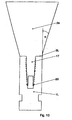
- FIGS. 1 to 5 show an implant 1 made of titanium, which has an approximately conical outer basic shape and is provided on its outer lateral surface with an external thread 2.
- the implant 1 has a rounded distal end 3 and a proximal end 4, which is formed by a substantially annular contact surface 5.
- the implant In a subsequent to the contact surface 5 section 6, the implant has outside a cylindrical shape with a highly polished lateral surface 7.
- the implant 1 In a subsequent threaded portion 8, the implant 1 is conically shaped. Starting from the contact surface 5, extending parallel to a longitudinal axis 9 of the implant 1, a receiving recess 10 which extends over the entire length of the portion 6 and a portion of the length of the threaded portion 8.
- the receiving recess 10 starting from the proximal end 4 of the implant 1, initially has a cylindrical section 10Z to which a section 10V tapering in cross-section adjoins.
- the connecting pin 17 of a replacement tooth to be inserted, starting from the head part 16 likewise initially has a cylindrical section 17Z whose diameter is slightly smaller than the diameter of the receiving recess 10 in its cylindrical section 10Z.
- the cylindrical section 17Z of the connecting pin 17 is adjoined by a section 17V tapering in cross-section.
- the length 6a of the cylindrical portion 17Z of the connecting pin 17 is dimensioned to be slightly smaller than the length 6b of the cylindrical portion 10Z of the receiving recess 10, it is excluded that in the region of the tapered portions 10V, 17V to a contact of the connecting pin 17 to the wall 12 of the receiving recess 10 comes. Rather, it is ensured by this type of component fit that always a full-surface contact surfaces 5 and 18 at the proximal end of the implant 1 is achieved.
- the difference between the lengths 6b and 6a, ie the axial distance between the peripheral edges 12a on the connecting pin 17 and 12b on the receiving recess 10 of the implant 1 is such that even in the worst case of manufacturing tolerances always a minimum distance in the sections 10V and 17V preserved. Otherwise, the difference in length should be kept as low as possible, to keep the gap in the region of the tapered portions 10V and 17V low.
- the cross-section of the receiving recess 10 in the area of the cylindrical portion 10Z has the shape of a rounded rectangle throughout.
- the cross-section of the receiving recess 10 in a subsequent section 10V continuously tapers so that at the base 11 of the receiving recess 10 the cross section has the shape of a rounded square (see FIG. In the threaded region 8, the transition from the rounded rectangular to the rounded square cross-sectional shape takes place continuously and without cracks.
- the wall 12 of the receiving recess 10 is provided with a plurality of annular grooves 13 which are aligned perpendicular to the longitudinal axis 9. Furthermore, the wall 12 is provided with an upper and a lower clip groove 14o and 14u, the function of which will be explained later with reference to FIG.
- a closure cap 15 is inserted, which consists of an approximately cylindrical head portion 16 and a coaxially aligned thereto connecting pin 17 which extends into the receiving recess 10.
- a contact surface 18 of the head part 16 comes to the contact surface 5 of the implant 1 force fit to the plant.
- the connecting pin 17 has an approximately rectangular cross-section in an upper section, wherein the corner regions are broken such that in the rounding regions of the cross section of the receiving recess 10 between the connecting pin 17 and the wall 12 of the receiving recess 10 four venting channels 19a are formed.
- the connecting pin 17 When inserting the connecting pin 17 into the receiving recess 10 displaced air can therefore, without it to a mounting process obstructing pressure build-up, be discharged upward, the air through four radially outwardly extending vent grooves 19 b, which introduced into the end face 5 of the implant are and communicate with the vent channels 19a, can escape to the outside.
- the closure cap Since the closure cap remains only temporarily after implantation on the implant 1, it is connected to the implant 1 only with the aid of four clip elements 20 which engage in the clip groove 140.
- the engagement of the clip elements 20 shown in FIG. 1 in the upper Clip groove 14o is also possible to engage in the lower clip groove 14u with a correspondingly extended connecting pin 17.
- the closure cap 15 is already inserted by the manufacturer of the implant 1 in this and serves on the one hand to the implant 1 after making a corresponding hole in the bone by means of a screwdriver, which engages in the slot 21 shown in Fig. 2, screwing. Due to the approximately rectangular cross section of the connecting pin 17 and the adapted receiving recess 10, a torque introduction via the closure cap 15 into the implant 1 is possible. After implantation, the closure cap 15 remains on the implant 1 in order to protect the receiving recess 10 from external contamination.
- the healing has been completed so far that the mucous membrane covering the closure cap 15 can be reopened in a second operation.
- the cap 15 is removed, which is intervened by means of a pliers-like tool in a V-shaped annular groove 22 in the head part 16 and thereby the entire cap 15 is removed by a slight jerk in the axial direction upward from the implant 1.
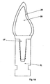
- a connecting pin 17 of a gingiva former 23 is used, as shown in Fig. 8.
- the fastening principle is the same as in the closure cap 15.
- a gingiva former 23 is conceivable in which the clip elements engage in the upper annular groove 14o.
- Fig. 9 shows a gingiva former with slit, which finds use in transgingival healing of the implant.
- FIG. 10 shows a laboratory implant 1 L into which a blank 24 of a provisional replacement tooth is likewise inserted by means of a connecting pin 17.
- the blank 24 is frusto-conical and widens, starting from the end face 5L of the laboratory implant 1 L, at an angle a of 15. In this way, misalignments of the implant 1 or 1 L compared to the adjacent teeth in wide angular ranges in all directions can be compensated.
- the connecting pin 17 of the blank 24 is also provided with clip elements 20, which ensure an uncomplicated fixing and removal of the blank 24.
- Fig. 11 shows a finished provisional replacement tooth 25, which was made by machining the blank 24 in a dental laboratory. On the ground blank, an outer ceramic layer 26 is fired.
- the finished provisional replacement tooth 25 can then be introduced into the implant 1 in the patient and fixed there with the aid of the clip elements 20 until the patient can be supplied with the final replacement tooth 28 (FIG. 12).
- This final replacement tooth 28, like the provisional replacement tooth 25, is made from a frusto-conical blank 27 (FIG. 13) in its head portion which allows for skew correction in all directions over wide angular ranges.
- the connecting pin 17 'derend claimeden replacement tooth 28 and the blank 27 has no clip elements, but is-apart from the region of the curves of the cross-sectional shape of the receiving recess 10 over the entire length of the connecting pin 17' adapted. Due to the annular grooves 13 in the wall 12 of the receiving recess 10, the connecting pin 17 can be introduced without problems until the end face of the head portion of the blank 27 comes to rest on the end face 51-of the laboratory implant 1 L.
- the termination of the restoration is that the final replacement tooth 28 is removed from the laboratory implant 1 L and inserted into the implant 1 located in the jawbone.
- the two contact surfaces 5 and 18 are frictionally against each other. Also between the outer lateral surfaces of the connecting pin 17 and the wall 12 of the receiving recess 10 is a frictional connection, which is made with the aid of adhesive or cement or formed in the case of a shrink connection by clamping forces.
- the lateral surface 29 of the connecting pin 17 'and the contact surface 18 of the head part are coated with a suitable adhesive or cement which essentially completely fills the annular grooves 13 in the receiving recess 10 when the connecting pin 17' is inserted.
- a suitable adhesive or cement which essentially completely fills the annular grooves 13 in the receiving recess 10 when the connecting pin 17' is inserted.
- Another non-positive connection is via the contact surfaces 5 and 18, wherein the adhesive is preferably applied in this area only so thin that the surface roughness of the contact surfaces are filled and it comes despite the adhesive to a material contact implant / replacement tooth. In any case, a protrusion of adhesive to the side of the contact surfaces 5 and 18 is to be avoided.
- connection between the replacement tooth 28 and the implant 1 can be further improved, even if in the lateral surface of the connecting pin 17 "a plurality of annular grooves 13" is present, which correspond to the annular grooves 13 in the wall 12 of the receiving recess 10.
- FIG. 16 Such a configuration is shown in FIG. 16.
- circular or oval-shaped adhesive rings are formed in cross section, which produce a positive connection between the replacement tooth 28 and the implant 1.
Landscapes
- Health & Medical Sciences (AREA)
- Oral & Maxillofacial Surgery (AREA)
- Orthopedic Medicine & Surgery (AREA)
- Dentistry (AREA)
- Epidemiology (AREA)
- Life Sciences & Earth Sciences (AREA)
- Animal Behavior & Ethology (AREA)
- General Health & Medical Sciences (AREA)
- Public Health (AREA)
- Veterinary Medicine (AREA)
- Dental Prosthetics (AREA)
- Prostheses (AREA)
Applications Claiming Priority (3)
| Application Number | Priority Date | Filing Date | Title |
|---|---|---|---|
| DE10019338 | 2000-04-19 | ||
| DE10019338A DE10019338B4 (de) | 2000-04-19 | 2000-04-19 | Implantat |
| PCT/EP2001/003948 WO2001080768A1 (de) | 2000-04-19 | 2001-04-06 | Medizinisches implantat |
Publications (2)
| Publication Number | Publication Date |
|---|---|
| EP1274364A1 EP1274364A1 (de) | 2003-01-15 |
| EP1274364B1 true EP1274364B1 (de) | 2007-01-17 |
Family
ID=7639276
Family Applications (1)
| Application Number | Title | Priority Date | Filing Date |
|---|---|---|---|
| EP01927885A Expired - Lifetime EP1274364B1 (de) | 2000-04-19 | 2001-04-06 | Medizinisches implantat |
Country Status (17)
| Country | Link |
|---|---|
| US (1) | US6840769B2 (pl) |
| EP (1) | EP1274364B1 (pl) |
| JP (1) | JP3764681B2 (pl) |
| CN (1) | CN1299651C (pl) |
| AU (2) | AU2001254786B2 (pl) |
| BR (1) | BR0110168B1 (pl) |
| CA (1) | CA2406759C (pl) |
| DE (2) | DE10019338B4 (pl) |
| DK (1) | DK1274364T3 (pl) |
| ES (1) | ES2277921T3 (pl) |
| IL (2) | IL152353A0 (pl) |
| MX (1) | MXPA02010238A (pl) |
| NO (1) | NO20024890L (pl) |
| PL (1) | PL194748B1 (pl) |
| PT (1) | PT1274364E (pl) |
| RU (1) | RU2234285C2 (pl) |
| WO (1) | WO2001080768A1 (pl) |
Families Citing this family (27)
| Publication number | Priority date | Publication date | Assignee | Title |
|---|---|---|---|---|
| DE10019331B4 (de) | 2000-04-19 | 2005-09-01 | Heraeus Kulzer Gmbh | Vorrichtung mit einem Stabelement und einem pfostenförmigen Element |
| DE10045543A1 (de) | 2000-09-13 | 2002-03-28 | Degussa | Steckverbindung für Kieferstumpfmodelle |
| EP1506745A1 (de) * | 2003-08-15 | 2005-02-16 | Jeanette Mörmann | Rohling und Verfahren zur Herstellung einer Zahnrestauration |
| SE526746C2 (sv) * | 2003-12-11 | 2005-11-01 | Nobel Biocare Ab | Implantat applicerbart i tandben med tillhörande mjukvävnad |
| FR2879122B1 (fr) | 2004-12-15 | 2008-10-03 | Inergy Automotive Systems Res | Procede pour la fabrication d'un reservoir a carburant en matiere plastique ayant une resistance au fluage amelioree |
| DE102005008273A1 (de) * | 2005-02-22 | 2006-08-24 | Mundorf, Sönke, Dr. | Ein- oder zweiteiliges Zahnimplantatsystem |
| DE102005027402A1 (de) * | 2005-06-13 | 2006-12-28 | Heraeus Kulzer Gmbh | Verfahren zur Herstellung eines individualisierten Ersatzzahns |
| DE102006007233A1 (de) * | 2006-02-15 | 2007-08-16 | Hager & Meisinger Gmbh | Formschlüssige Fixierung eines Stift-Stumpfaufbaus in einem menschlichen Zahn mittels Spreizbohrer und -stift |
| DE102006040516A1 (de) * | 2006-08-30 | 2008-03-06 | Prokuro Gmbh | Verbindungselement für Abutment und Implantat sowie ein Implantatsystem |
| WO2008111068A1 (en) * | 2007-03-15 | 2008-09-18 | A.B. Dental Devices Ltd | Device providing an interface between a dental implant and an abutment |
| DE102007045154A1 (de) | 2007-09-20 | 2009-04-09 | Heraeus Kulzer Gmbh | Mischkapsel für Zweikomponentenmaterial |
| US20090298008A1 (en) * | 2008-05-29 | 2009-12-03 | Ibur, L.L.C. | Dental x-ray and drill guide apparatus and method |
| DE102008028232A1 (de) | 2008-06-16 | 2009-12-17 | Heraeus Kulzer Gmbh | Dental-Vorschub-Dosierung |
| EP2353540A1 (fr) * | 2010-01-28 | 2011-08-10 | Sudimplant | Ensemble d'un implant dentaire et d'un élément prothétique |
| US9585695B2 (en) | 2013-03-15 | 2017-03-07 | Woven Orthopedic Technologies, Llc | Surgical screw hole liner devices and related methods |
| US8956394B1 (en) | 2014-08-05 | 2015-02-17 | Woven Orthopedic Technologies, Llc | Woven retention devices, systems and methods |
| US9907593B2 (en) | 2014-08-05 | 2018-03-06 | Woven Orthopedic Technologies, Llc | Woven retention devices, systems and methods |
| US20160074071A1 (en) | 2014-09-16 | 2016-03-17 | Woven Orthopedic Technologies, Llc | Methods of using woven retention devices and systems |
| USD740427S1 (en) | 2014-10-17 | 2015-10-06 | Woven Orthopedic Technologies, Llc | Orthopedic woven retention device |
| BR102014031426B1 (pt) | 2014-12-15 | 2018-07-24 | Jjgc Ind E Comercio De Materiais Dentarios S/A | implante |
| CL2015001657S1 (es) | 2014-12-15 | 2016-09-02 | Jjgc Indústria E Comércio De Materiais Dentários S A | Configuracion aplicada a implante oseo. |
| EP3331459A4 (en) | 2015-08-05 | 2019-08-14 | Woven Orthopedic Technologies, LLC | DEVICES, SYSTEMS, AND METHODS OF COLLECTION FOR USE IN BONE TISSUE |
| BR102016010184B1 (pt) | 2016-05-05 | 2020-10-27 | Jjgc Indústria E Comércio De Materiais Dentários S.A. | conjunto protético e processo para produção do mesmo |
| US11395681B2 (en) | 2016-12-09 | 2022-07-26 | Woven Orthopedic Technologies, Llc | Retention devices, lattices and related systems and methods |
| KR102055821B1 (ko) * | 2017-09-18 | 2019-12-16 | 오스템임플란트 주식회사 | 치과용 임플란트 조립체 및 그 제조방법 |
| DE102019100016A1 (de) * | 2019-01-02 | 2020-07-02 | Aesculap Ag | Fügeverfahren für eine medizintechnische Vorrichtung |
| CN114366354B (zh) * | 2021-12-31 | 2024-05-17 | 北京劲松口腔医院投资管理有限公司 | 一种用于牙槽骨缺失的钛网构件及其制作方法 |
Family Cites Families (19)
| Publication number | Priority date | Publication date | Assignee | Title |
|---|---|---|---|---|
| DE353395C (de) * | 1922-05-16 | Magnet Werk G M B H Eisenach | Einrichtung zum Trennen des Ankers vom Magneten bei elektromagnetisch bewegten Umkehrgetrieben | |
| DE3241963C1 (de) | 1982-11-12 | 1984-04-26 | Feldmühle AG, 4000 Düsseldorf | Schraubenfoermig ausgebildetes Kieferimplantat |
| DE3300764A1 (de) * | 1983-01-12 | 1984-07-12 | Johannes Bademis | Kieferimplantat aus einem implantatkoerper und einem darauf befestigbaren mobilen aufsatz |
| AT380780B (de) * | 1984-09-21 | 1986-07-10 | Koinig Horst | Implantat |
| JPH0712365B2 (ja) * | 1985-04-04 | 1995-02-15 | オリンパス光学工業株式会社 | 人工歯根 |
| DE3917690A1 (de) * | 1989-05-31 | 1990-12-13 | Kirsch Axel | Enossales einzelzahnimplantat sowie konterwerkzeug zur verwendung bei einem derartigen implantat |
| US5030095A (en) * | 1989-08-16 | 1991-07-09 | Niznick Gerald A | Angled abutment for endosseous implants |
| DE4127436A1 (de) * | 1990-08-21 | 1992-03-05 | Gerold Klaus | Vorrichtung zur befestigung einer zahnprothese an implantaten oder wurzelkappen |
| DE4127839A1 (de) * | 1990-09-01 | 1992-03-19 | Gerold Klaus | Vorrichtung zum befestigen von zahnersatz an einem implantat |
| DE4028857A1 (de) * | 1990-09-08 | 1992-03-12 | Eberle Medizintech Elemente | Enossales implantat fuer einen festsitzenden zahnersatz |
| US5197881A (en) * | 1991-12-30 | 1993-03-30 | Wellesley Research Associates, Inc. | Dental implant system and apparatus |
| US5246370A (en) * | 1992-11-27 | 1993-09-21 | Coatoam Gary W | Dental implant method |
| AT400804B (de) * | 1994-10-10 | 1996-03-25 | Mke Metall Kunststoffwaren | Implantat |
| US5961328A (en) * | 1995-01-23 | 1999-10-05 | Somborac; Milan | Dental implant |
| DE29605296U1 (de) * | 1996-03-21 | 1996-05-30 | Zahntechnisches Atelier Lothar | Aufbauteil für zahnärztliche Suprakonstruktionen |
| US6290500B1 (en) | 1997-12-10 | 2001-09-18 | Diro, Inc. | Dental implant system and method |
| US6273720B1 (en) * | 1999-04-20 | 2001-08-14 | Robert Spalten | Dental implant system |
| WO2000064384A1 (de) | 1999-04-27 | 2000-11-02 | Steinicke Maschinen- Und Werkzeugbau Ag | Endoprothese, insbesondere für ein künstliches hüftgelenk |
| US6358052B1 (en) * | 1999-07-15 | 2002-03-19 | L. Paul Lustig | Dental implant system and method for effecting a dental restoration using the same |
-
2000
- 2000-04-19 DE DE10019338A patent/DE10019338B4/de not_active Expired - Fee Related
-
2001
- 2001-04-06 AU AU2001254786A patent/AU2001254786B2/en not_active Ceased
- 2001-04-06 AU AU5478601A patent/AU5478601A/xx active Pending
- 2001-04-06 ES ES01927885T patent/ES2277921T3/es not_active Expired - Lifetime
- 2001-04-06 PL PL01357951A patent/PL194748B1/pl not_active IP Right Cessation
- 2001-04-06 DE DE50111900T patent/DE50111900D1/de not_active Expired - Lifetime
- 2001-04-06 WO PCT/EP2001/003948 patent/WO2001080768A1/de active IP Right Grant
- 2001-04-06 JP JP2001577871A patent/JP3764681B2/ja not_active Expired - Fee Related
- 2001-04-06 BR BRPI0110168-4A patent/BR0110168B1/pt not_active IP Right Cessation
- 2001-04-06 US US10/257,926 patent/US6840769B2/en not_active Expired - Fee Related
- 2001-04-06 CN CNB018082483A patent/CN1299651C/zh not_active Expired - Fee Related
- 2001-04-06 CA CA002406759A patent/CA2406759C/en not_active Expired - Fee Related
- 2001-04-06 PT PT01927885T patent/PT1274364E/pt unknown
- 2001-04-06 EP EP01927885A patent/EP1274364B1/de not_active Expired - Lifetime
- 2001-04-06 RU RU2002130826/14A patent/RU2234285C2/ru not_active IP Right Cessation
- 2001-04-06 IL IL15235301A patent/IL152353A0/xx active IP Right Grant
- 2001-04-06 DK DK01927885T patent/DK1274364T3/da active
- 2001-04-06 MX MXPA02010238A patent/MXPA02010238A/es active IP Right Grant
-
2002
- 2002-10-10 NO NO20024890A patent/NO20024890L/no not_active Application Discontinuation
- 2002-10-17 IL IL152353A patent/IL152353A/en not_active IP Right Cessation
Also Published As
| Publication number | Publication date |
|---|---|
| AU5478601A (en) | 2001-11-07 |
| AU2001254786B2 (en) | 2006-03-30 |
| BR0110168B1 (pt) | 2010-09-21 |
| US6840769B2 (en) | 2005-01-11 |
| CN1299651C (zh) | 2007-02-14 |
| BR0110168A (pt) | 2003-02-25 |
| JP3764681B2 (ja) | 2006-04-12 |
| DE50111900D1 (de) | 2007-03-08 |
| IL152353A0 (en) | 2003-05-29 |
| PT1274364E (pt) | 2007-03-30 |
| ES2277921T3 (es) | 2007-08-01 |
| WO2001080768A1 (de) | 2001-11-01 |
| DE10019338B4 (de) | 2007-06-06 |
| DK1274364T3 (da) | 2007-05-21 |
| NO20024890D0 (no) | 2002-10-10 |
| CA2406759A1 (en) | 2002-10-18 |
| DE10019338A1 (de) | 2001-11-08 |
| PL357951A1 (pl) | 2004-08-09 |
| CA2406759C (en) | 2007-07-17 |
| NO20024890L (no) | 2002-10-10 |
| CN1424893A (zh) | 2003-06-18 |
| IL152353A (en) | 2007-08-19 |
| RU2234285C2 (ru) | 2004-08-20 |
| RU2002130826A (ru) | 2004-03-20 |
| PL194748B1 (pl) | 2007-06-29 |
| US20030157459A1 (en) | 2003-08-21 |
| EP1274364A1 (de) | 2003-01-15 |
| MXPA02010238A (es) | 2003-04-25 |
| JP2003530951A (ja) | 2003-10-21 |
Similar Documents
| Publication | Publication Date | Title |
|---|---|---|
| EP1274364B1 (de) | Medizinisches implantat | |
| EP1274367B1 (de) | Implantat | |
| EP1100395B1 (de) | Vorrichtung zum halten und/oder bilden eines zahnersatzes | |
| EP2607722B1 (de) | Verbindungsschraube für ein Dentalimplantat | |
| EP0513943B1 (de) | Implantat mit Pressfläche | |
| EP1850784B1 (de) | Zahnimplantat | |
| EP3496653B1 (de) | Dentalimplantat mit buchsenkörper und bausatz für selbiges | |
| WO1998052490A1 (de) | Vorrichtung zur bildung eines zahnersatzes | |
| EP0438048A1 (de) | Dentalimplantat | |
| EP2674127B1 (de) | Implantat | |
| WO2006017995A1 (de) | Einschraubbares enossales dentalimplantat | |
| DE4326841A1 (de) | Implantat-Bausatz | |
| EP1274365B1 (de) | Pfostenförmiges element zur bestimmung der räumlichen position eines implantats | |
| EP1018319B1 (de) | Kieferimplantat | |
| EP3542750A1 (de) | Dentalimplantatsystem | |
| EP0896812A1 (de) | Implantateinsatz zum Fördern des Wachstums der Gingiva | |
| EP3542751A1 (de) | Dentalimplantatsystem | |
| WO1998048726A1 (de) | Konusförmiges implantat | |
| EP3914188B1 (de) | Okklusalschraube, dentalimplantatsystem und set | |
| EP0984736B1 (de) | Konusförmiges implantat |
Legal Events
| Date | Code | Title | Description |
|---|---|---|---|
| PUAI | Public reference made under article 153(3) epc to a published international application that has entered the european phase |
Free format text: ORIGINAL CODE: 0009012 |
|
| 17P | Request for examination filed |
Effective date: 20020911 |
|
| AK | Designated contracting states |
Kind code of ref document: A1 Designated state(s): AT BE CH CY DE DK ES FI FR GB GR IE IT LI LU MC NL PT SE TR |
|
| RIN1 | Information on inventor provided before grant (corrected) |
Inventor name: AUGTHUN, MICHAEL Inventor name: PETERS, MANFRED Inventor name: HASELHUHN, KLAUS Inventor name: SPIEKERMANN, HUBERTUS |
|
| RAP1 | Party data changed (applicant data changed or rights of an application transferred) |
Owner name: HERAEUS KULZER GMBH |
|
| RAP1 | Party data changed (applicant data changed or rights of an application transferred) |
Owner name: HERAEUS KULZER GMBH |
|
| GRAP | Despatch of communication of intention to grant a patent |
Free format text: ORIGINAL CODE: EPIDOSNIGR1 |
|
| GRAS | Grant fee paid |
Free format text: ORIGINAL CODE: EPIDOSNIGR3 |
|
| GRAA | (expected) grant |
Free format text: ORIGINAL CODE: 0009210 |
|
| AK | Designated contracting states |
Kind code of ref document: B1 Designated state(s): AT BE CH CY DE DK ES FI FR GB GR IE IT LI LU MC NL PT SE TR |
|
| REG | Reference to a national code |
Ref country code: GB Ref legal event code: FG4D Free format text: NOT ENGLISH |
|
| REG | Reference to a national code |
Ref country code: CH Ref legal event code: NV Representative=s name: KIRKER & CIE SA Ref country code: CH Ref legal event code: EP |
|
| REG | Reference to a national code |
Ref country code: IE Ref legal event code: FG4D Free format text: LANGUAGE OF EP DOCUMENT: GERMAN |
|
| REF | Corresponds to: |
Ref document number: 50111900 Country of ref document: DE Date of ref document: 20070308 Kind code of ref document: P |
|
| REG | Reference to a national code |
Ref country code: PT Ref legal event code: SC4A Free format text: AVAILABILITY OF NATIONAL TRANSLATION Effective date: 20070223 |
|
| GBT | Gb: translation of ep patent filed (gb section 77(6)(a)/1977) |
Effective date: 20070329 |
|
| REG | Reference to a national code |
Ref country code: GR Ref legal event code: EP Ref document number: 20070400991 Country of ref document: GR |
|
| REG | Reference to a national code |
Ref country code: SE Ref legal event code: TRGR |
|
| REG | Reference to a national code |
Ref country code: DK Ref legal event code: T3 |
|
| REG | Reference to a national code |
Ref country code: ES Ref legal event code: FG2A Ref document number: 2277921 Country of ref document: ES Kind code of ref document: T3 |
|
| ET | Fr: translation filed | ||
| PLBE | No opposition filed within time limit |
Free format text: ORIGINAL CODE: 0009261 |
|
| STAA | Information on the status of an ep patent application or granted ep patent |
Free format text: STATUS: NO OPPOSITION FILED WITHIN TIME LIMIT |
|
| 26N | No opposition filed |
Effective date: 20071018 |
|
| PG25 | Lapsed in a contracting state [announced via postgrant information from national office to epo] |
Ref country code: MC Free format text: LAPSE BECAUSE OF NON-PAYMENT OF DUE FEES Effective date: 20070430 |
|
| PG25 | Lapsed in a contracting state [announced via postgrant information from national office to epo] |
Ref country code: CY Free format text: LAPSE BECAUSE OF FAILURE TO SUBMIT A TRANSLATION OF THE DESCRIPTION OR TO PAY THE FEE WITHIN THE PRESCRIBED TIME-LIMIT Effective date: 20070117 |
|
| PGFP | Annual fee paid to national office [announced via postgrant information from national office to epo] |
Ref country code: TR Payment date: 20100323 Year of fee payment: 10 |
|
| PGFP | Annual fee paid to national office [announced via postgrant information from national office to epo] |
Ref country code: LU Payment date: 20110429 Year of fee payment: 11 |
|
| PGFP | Annual fee paid to national office [announced via postgrant information from national office to epo] |
Ref country code: SE Payment date: 20110414 Year of fee payment: 11 Ref country code: FR Payment date: 20110510 Year of fee payment: 11 Ref country code: DE Payment date: 20110421 Year of fee payment: 11 Ref country code: GR Payment date: 20110418 Year of fee payment: 11 Ref country code: IE Payment date: 20110426 Year of fee payment: 11 Ref country code: CH Payment date: 20110428 Year of fee payment: 11 Ref country code: ES Payment date: 20110426 Year of fee payment: 11 Ref country code: PT Payment date: 20110401 Year of fee payment: 11 |
|
| PGFP | Annual fee paid to national office [announced via postgrant information from national office to epo] |
Ref country code: NL Payment date: 20110426 Year of fee payment: 11 Ref country code: DK Payment date: 20110418 Year of fee payment: 11 Ref country code: GB Payment date: 20110421 Year of fee payment: 11 Ref country code: BE Payment date: 20110414 Year of fee payment: 11 Ref country code: FI Payment date: 20110414 Year of fee payment: 11 Ref country code: AT Payment date: 20110414 Year of fee payment: 11 |
|
| PGFP | Annual fee paid to national office [announced via postgrant information from national office to epo] |
Ref country code: IT Payment date: 20110421 Year of fee payment: 11 |
|
| REG | Reference to a national code |
Ref country code: PT Ref legal event code: MM4A Free format text: LAPSE DUE TO NON-PAYMENT OF FEES Effective date: 20121008 |
|
| BERE | Be: lapsed |
Owner name: HERAEUS KULZER G.M.B.H. Effective date: 20120430 |
|
| REG | Reference to a national code |
Ref country code: NL Ref legal event code: V1 Effective date: 20121101 |
|
| REG | Reference to a national code |
Ref country code: DK Ref legal event code: EBP |
|
| REG | Reference to a national code |
Ref country code: CH Ref legal event code: PL |
|
| REG | Reference to a national code |
Ref country code: SE Ref legal event code: EUG |
|
| REG | Reference to a national code |
Ref country code: AT Ref legal event code: MM01 Ref document number: 351612 Country of ref document: AT Kind code of ref document: T Effective date: 20120406 |
|
| GBPC | Gb: european patent ceased through non-payment of renewal fee |
Effective date: 20120406 |
|
| REG | Reference to a national code |
Ref country code: IE Ref legal event code: MM4A |
|
| REG | Reference to a national code |
Ref country code: FR Ref legal event code: ST Effective date: 20121228 |
|
| REG | Reference to a national code |
Ref country code: GR Ref legal event code: ML Ref document number: 20070400991 Country of ref document: GR Effective date: 20121102 |
|
| PG25 | Lapsed in a contracting state [announced via postgrant information from national office to epo] |
Ref country code: GB Free format text: LAPSE BECAUSE OF NON-PAYMENT OF DUE FEES Effective date: 20120406 Ref country code: AT Free format text: LAPSE BECAUSE OF NON-PAYMENT OF DUE FEES Effective date: 20120406 Ref country code: FI Free format text: LAPSE BECAUSE OF NON-PAYMENT OF DUE FEES Effective date: 20120406 Ref country code: BE Free format text: LAPSE BECAUSE OF NON-PAYMENT OF DUE FEES Effective date: 20120430 Ref country code: IE Free format text: LAPSE BECAUSE OF NON-PAYMENT OF DUE FEES Effective date: 20120406 Ref country code: LI Free format text: LAPSE BECAUSE OF NON-PAYMENT OF DUE FEES Effective date: 20120430 Ref country code: CH Free format text: LAPSE BECAUSE OF NON-PAYMENT OF DUE FEES Effective date: 20120430 |
|
| REG | Reference to a national code |
Ref country code: DE Ref legal event code: R119 Ref document number: 50111900 Country of ref document: DE Effective date: 20121101 |
|
| PG25 | Lapsed in a contracting state [announced via postgrant information from national office to epo] |
Ref country code: GR Free format text: LAPSE BECAUSE OF NON-PAYMENT OF DUE FEES Effective date: 20121102 Ref country code: IT Free format text: LAPSE BECAUSE OF NON-PAYMENT OF DUE FEES Effective date: 20120406 Ref country code: SE Free format text: LAPSE BECAUSE OF NON-PAYMENT OF DUE FEES Effective date: 20120407 Ref country code: FR Free format text: LAPSE BECAUSE OF NON-PAYMENT OF DUE FEES Effective date: 20120430 Ref country code: PT Free format text: LAPSE BECAUSE OF NON-PAYMENT OF DUE FEES Effective date: 20121008 |
|
| PG25 | Lapsed in a contracting state [announced via postgrant information from national office to epo] |
Ref country code: NL Free format text: LAPSE BECAUSE OF NON-PAYMENT OF DUE FEES Effective date: 20121101 |
|
| REG | Reference to a national code |
Ref country code: ES Ref legal event code: FD2A Effective date: 20130822 |
|
| PG25 | Lapsed in a contracting state [announced via postgrant information from national office to epo] |
Ref country code: ES Free format text: LAPSE BECAUSE OF NON-PAYMENT OF DUE FEES Effective date: 20120407 Ref country code: DK Free format text: LAPSE BECAUSE OF NON-PAYMENT OF DUE FEES Effective date: 20120430 Ref country code: TR Free format text: LAPSE BECAUSE OF NON-PAYMENT OF DUE FEES Effective date: 20120405 |
|
| PG25 | Lapsed in a contracting state [announced via postgrant information from national office to epo] |
Ref country code: TR Free format text: LAPSE BECAUSE OF NON-PAYMENT OF DUE FEES Effective date: 20120406 |
|
| PG25 | Lapsed in a contracting state [announced via postgrant information from national office to epo] |
Ref country code: LU Free format text: LAPSE BECAUSE OF NON-PAYMENT OF DUE FEES Effective date: 20120406 |
|
| PG25 | Lapsed in a contracting state [announced via postgrant information from national office to epo] |
Ref country code: DE Free format text: LAPSE BECAUSE OF NON-PAYMENT OF DUE FEES Effective date: 20121101 |