EP1274364B1 - Medical implant - Google Patents
Medical implant Download PDFInfo
- Publication number
- EP1274364B1 EP1274364B1 EP01927885A EP01927885A EP1274364B1 EP 1274364 B1 EP1274364 B1 EP 1274364B1 EP 01927885 A EP01927885 A EP 01927885A EP 01927885 A EP01927885 A EP 01927885A EP 1274364 B1 EP1274364 B1 EP 1274364B1
- Authority
- EP
- European Patent Office
- Prior art keywords
- implant
- section
- receiving recess
- cross
- proximal end
- Prior art date
- Legal status (The legal status is an assumption and is not a legal conclusion. Google has not performed a legal analysis and makes no representation as to the accuracy of the status listed.)
- Expired - Lifetime
Links
Images


Classifications
-
- A—HUMAN NECESSITIES
- A61—MEDICAL OR VETERINARY SCIENCE; HYGIENE
- A61C—DENTISTRY; APPARATUS OR METHODS FOR ORAL OR DENTAL HYGIENE
- A61C8/00—Means to be fixed to the jaw-bone for consolidating natural teeth or for fixing dental prostheses thereon; Dental implants; Implanting tools
- A61C8/0048—Connecting the upper structure to the implant, e.g. bridging bars
- A61C8/005—Connecting devices for joining an upper structure with an implant member, e.g. spacers
- A61C8/0054—Connecting devices for joining an upper structure with an implant member, e.g. spacers having a cylindrical implant connecting part
-
- A—HUMAN NECESSITIES
- A61—MEDICAL OR VETERINARY SCIENCE; HYGIENE
- A61C—DENTISTRY; APPARATUS OR METHODS FOR ORAL OR DENTAL HYGIENE
- A61C8/00—Means to be fixed to the jaw-bone for consolidating natural teeth or for fixing dental prostheses thereon; Dental implants; Implanting tools
- A61C8/0048—Connecting the upper structure to the implant, e.g. bridging bars
- A61C8/005—Connecting devices for joining an upper structure with an implant member, e.g. spacers
- A61C8/0069—Connecting devices for joining an upper structure with an implant member, e.g. spacers tapered or conical connection
- A61C8/0071—Connecting devices for joining an upper structure with an implant member, e.g. spacers tapered or conical connection with a self-locking taper, e.g. morse taper
-
- A—HUMAN NECESSITIES
- A61—MEDICAL OR VETERINARY SCIENCE; HYGIENE
- A61F—FILTERS IMPLANTABLE INTO BLOOD VESSELS; PROSTHESES; DEVICES PROVIDING PATENCY TO, OR PREVENTING COLLAPSING OF, TUBULAR STRUCTURES OF THE BODY, e.g. STENTS; ORTHOPAEDIC, NURSING OR CONTRACEPTIVE DEVICES; FOMENTATION; TREATMENT OR PROTECTION OF EYES OR EARS; BANDAGES, DRESSINGS OR ABSORBENT PADS; FIRST-AID KITS
- A61F2/00—Filters implantable into blood vessels; Prostheses, i.e. artificial substitutes or replacements for parts of the body; Appliances for connecting them with the body; Devices providing patency to, or preventing collapsing of, tubular structures of the body, e.g. stents
- A61F2/02—Prostheses implantable into the body
- A61F2/30—Joints
- A61F2002/30001—Additional features of subject-matter classified in A61F2/28, A61F2/30 and subgroups thereof
- A61F2002/30316—The prosthesis having different structural features at different locations within the same prosthesis; Connections between prosthetic parts; Special structural features of bone or joint prostheses not otherwise provided for
- A61F2002/30329—Connections or couplings between prosthetic parts, e.g. between modular parts; Connecting elements
- A61F2002/30331—Connections or couplings between prosthetic parts, e.g. between modular parts; Connecting elements made by longitudinally pushing a protrusion into a complementarily-shaped recess, e.g. held by friction fit
- A61F2002/30359—Pyramidally- or frustopyramidally-shaped protrusion and recess
-
- A—HUMAN NECESSITIES
- A61—MEDICAL OR VETERINARY SCIENCE; HYGIENE
- A61F—FILTERS IMPLANTABLE INTO BLOOD VESSELS; PROSTHESES; DEVICES PROVIDING PATENCY TO, OR PREVENTING COLLAPSING OF, TUBULAR STRUCTURES OF THE BODY, e.g. STENTS; ORTHOPAEDIC, NURSING OR CONTRACEPTIVE DEVICES; FOMENTATION; TREATMENT OR PROTECTION OF EYES OR EARS; BANDAGES, DRESSINGS OR ABSORBENT PADS; FIRST-AID KITS
- A61F2220/00—Fixations or connections for prostheses classified in groups A61F2/00 - A61F2/26 or A61F2/82 or A61F9/00 or A61F11/00 or subgroups thereof
- A61F2220/0025—Connections or couplings between prosthetic parts, e.g. between modular parts; Connecting elements
- A61F2220/0033—Connections or couplings between prosthetic parts, e.g. between modular parts; Connecting elements made by longitudinally pushing a protrusion into a complementary-shaped recess, e.g. held by friction fit
Definitions
- the invention relates to an implant for receiving a connecting pin of a medical element, having a longitudinal axis, a distal end and a proximal end, from which a receiving recess for the connecting pin extends into the interior of the implant, wherein the implant on its outer circumferential surface kraft-.
- the adapted to the receiving recess connecting pin is anchored in this by clamping, shrinking, gluing or cementing, wherein the medical element in the anchored state with a contact surface of a in its cross section over the cross section of the receiving recess at the proximal end of the implant radially outwardly projecting head part over its entire surface against an associated contact surface of the implant at its proximal end and the outer contour of the Querschn itts the receiving recess is not circular at least in one section.
- Such implant systems are widely used, for example, in the dental field.
- the male medical element z. B. formed by a replacement tooth, a cap or a gingiva former.
- the implant is screwed into the jawbone, for example.
- an implant system of the type described above is known for example from US 5,961,328.
- the connecting pin of the medical element and the receiving recess of the implant cooperate according to a key-lock principle, wherein a security against rotation by means of radially above the connecting pin projecting closure elements is achieved, which in the inserted state of the medical element in it adapted recesses in the head part of the implant intervention.
- the receiving recess initially has a conical section, adjoined by a cylindrical section whose cross section corresponds to the cross section at the end of the conical section.
- the connecting pin of the medical element to be inserted into the receiving recess has a cross section in the direction of distal end toward tapered shape, wherein the outer contour of the connecting pin is concave in a longitudinal section and has a sawtooth-like surface structure.
- the cross-section of the connecting pin is not circular, but rather lacks in comparison to a rotationally symmetrical design on one side a longitudinal strip, so that a flat surface portion of the lateral surface forms, which is parallel to the longitudinal axis of the connecting pin.
- the replacement tooth known from WO99 / 29255 consists of a connecting pin with a lower part, a central part and an upper part, and a crown pushed onto the upper part.
- the replacement tooth is used as a whole with its conical lower part in an adapted, also conical receiving bore in an implant that has previously been inserted into the jawbone and must be sufficiently healed therein.
- the principle of a clamping cone is used in the connection between the connecting pin and the receiving bore.
- a screw connection between the replacement tooth and the implant is the most widespread type of connection, which is characterized by its simple reversibility.
- the disadvantage is the large amount of time required for screwing in the fastening screws, especially for a larger number of replacement teeth and the often unsatisfactory durability of such systems.
- undefined load conditions which can result in unwanted deformations and voltage spikes. Either this can lead to damage to the screw connection or overloading of the connection between implant and bone, which in the worst case can lead to a total loss of the implant.
- DE4127839A1 relates to a device for fixing dentures on an implant, wherein the holding part in the implant (1) can be positively inserted in different rotational angle positions.
- the holding part can be used in particular with a polygonal section in a correspondingly formed, offset polygonal receptacle in the implant in different rotational angle positions, wherein a molded after the polygonal section retention part engages in a die of the implant. The final attachment is not explained in detail.
- US5246370 describes an implant system in which the abutment fits into a funnel-shaped recess on the implant post and screwed there we.
- the invention has for its object to propose an implant system in which the connection between the medical element and the implant can be produced in a simple manner, the compound should be characterized by a uniform large-scale introduction of force and a rotation.
- this object is achieved in that the receiving recess, starting from the proximal end of the implant has a cylindrical portion, followed by a tapered in cross-section 7 and that the connecting pin, starting from the top of the medical element also has a cylindrical portion, followed by a tapered in cross section section.
- the full-surface contact area causes uniform force transmission from the medical element into the implant, which avoids voltage peaks and thus material overloads and damage.
- the cylindrical portion of the connecting pin in conjunction with the adapted cylindrical portion of the receiving recess causes a secure fixation in which also an extremely lateral force introduction into the medical element do not lead to tensile force components in the interface between the medical element and the inner circumferential surface of the implant.
- the security against loosening and falling out is therefore particularly large in the inventive implant, regardless of whether the medical element is shrunk, glued or cemented.
- the non-circular cross-section which may, for example, be in the shape of a (rounded) polygon (triangle, quadrilateral, pentagon, etc.) or an ellipse or oval or any other sheet, prevents rotation of the medical element connecting pin about its longitudinal axis is possible. Due to the clearly defined angular position of the medical element with respect to a rotation about the vertical axis also eliminates a complicated adjustment of the position of the medical element during insertion.
- the actual connection between implant and connecting pin is made by clamping, shrinking, gluing or cementing.
- the length of the cylindrical section of the connecting pin measured in the direction of the longitudinal axis of the implant is slightly smaller than the length of the cylindrical section of the receiving recess which is likewise measured in the direction of the longitudinal axis of the implant.
- the difference in the lengths should be such that, taking into account the manufacturing tolerances of the individual elements, even in the worst case, a system always occurs in the area of the contact surfaces. Too large a choice of the longitudinal difference should be avoided, however, in order to avoid unnecessarily large gaps between the connecting pin and the receiving recess in the region of the tapered cross sections.
- a particularly advantageous embodiment is the fact that the contact surface is annular and extends in a plane perpendicular to the longitudinal axis of the implant.
- venting groove is present in the contact surface of the implant, which extends from a venting channel to the outer surface of the implant. In this way, a completely unhindered outflow of air displaced by the connecting pin is ensured.
- the connecting pin is dimensioned in comparison to the receiving bore so that the connecting pin can be inserted so far into the receiving recess in any case until the contact surface of its head part comes to rest on the contact surface of the implant over its entire surface.
- a development of the implant according to the invention consists in that the wall of the receiving recess is provided with a plurality of annular grooves, each extending in planes perpendicular to the longitudinal axis of the implant, or with a helical groove.
- the annular grooves or the helical groove ensure that the assembly process, in particular in its last phase, is facilitated. In particular, a wringing of abutting surfaces for abutment is prevented and a better guidance of the connecting pin is achieved.
- a helical bead of adhesive is generated, can be absorbed via the axial forces.
- the invention epicausgestaltend, it is proposed that the wall of the receiving recess is provided with at least one recess with which an elastic clip element of a medical element, that is z. B. a cap, a gingiva Forrners, an impression post and / or a provisional replacement tooth can be brought into positive engagement.
- a medical element that is z. B. a cap, a gingiva Forrners, an impression post and / or a provisional replacement tooth
- all components that need only be temporarily connected to the implant, used in the simplest way in the receiving recess and thereby be connected in a precisely predetermined position with the implant.
- the clip element creates a positive connection which can be reversed again by means of a corresponding axial force, which is why the clip quantities are advantageously slightly rounded in order to permit non-destructive separation.
- the power transmission takes place in the transitional period via the end faces. The time required for establishing the connection between the components used only temporarily and the implant is drastically reduced, which manifests itself
- the cross-section of the receiving recess in the vicinity of the proximal end of the implant has the shape of a rounded rectangle and in the vicinity of its base the shape of a rounded square, the transition between the aforementioned cross-sectional shapes taking place without jumps. It makes sense that the shorter edge length of the rectangle corresponds to the edge length of the square.
- a medical element which, with a contact surface of a cross section over the cross section of the receiving recess at the proximal end radially outwardly projecting head portion over the entire surface of an associated contact surface of the implant at its proximal end and in which the outer contour of the Cross-section of the connecting pin is not circular at least in one section.
- the connecting pin has in the vicinity of its proximal end a cross-section in the form of a rectangle whose corners are more rounded or broken than those of the rectangle of the cross-section of the receiving recess in the anchored state associated body, and in the vicinity of its distal end a cross-section in the form of a rounded square, whose corners are more rounded than that of the square of the cross-section of the receiving recess at the assigned position in the anchored state.
- the distal end of the connecting pin has at least one axially projecting clip element, which in the installed state can be brought into positive engagement with a recess in the receiving recess of the implant.
- the positive connection via the clip element summarizes itself in a particularly simple manner cancel again if a section located in the installed state outside of the receiving recess is provided in its lateral surface with at least two opposite recesses.
- hook-shaped contact elements of a forceps-shaped tool can be introduced with which z.
- a clipped cap a clipped gingiva former, impression posts and / or provisional replacement tooth can be easily removed by applying a corresponding axial force again from the implant.
- the invention further refinement, it is provided in a final replacement tooth, that the lateral surface of the connecting pin with a plurality of annular grooves, each extending in a plane perpendicular to the longitudinal axis of the connecting pin, provided in the anchored state of the replacement tooth with the annular grooves in the wall of the Receiving recess correspond.
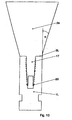
- FIGS. 1 to 5 show an implant 1 made of titanium, which has an approximately conical outer basic shape and is provided on its outer lateral surface with an external thread 2.
- the implant 1 has a rounded distal end 3 and a proximal end 4, which is formed by a substantially annular contact surface 5.
- the implant In a subsequent to the contact surface 5 section 6, the implant has outside a cylindrical shape with a highly polished lateral surface 7.
- the implant 1 In a subsequent threaded portion 8, the implant 1 is conically shaped. Starting from the contact surface 5, extending parallel to a longitudinal axis 9 of the implant 1, a receiving recess 10 which extends over the entire length of the portion 6 and a portion of the length of the threaded portion 8.
- the receiving recess 10 starting from the proximal end 4 of the implant 1, initially has a cylindrical section 10Z to which a section 10V tapering in cross-section adjoins.
- the connecting pin 17 of a replacement tooth to be inserted, starting from the head part 16 likewise initially has a cylindrical section 17Z whose diameter is slightly smaller than the diameter of the receiving recess 10 in its cylindrical section 10Z.
- the cylindrical section 17Z of the connecting pin 17 is adjoined by a section 17V tapering in cross-section.
- the length 6a of the cylindrical portion 17Z of the connecting pin 17 is dimensioned to be slightly smaller than the length 6b of the cylindrical portion 10Z of the receiving recess 10, it is excluded that in the region of the tapered portions 10V, 17V to a contact of the connecting pin 17 to the wall 12 of the receiving recess 10 comes. Rather, it is ensured by this type of component fit that always a full-surface contact surfaces 5 and 18 at the proximal end of the implant 1 is achieved.
- the difference between the lengths 6b and 6a, ie the axial distance between the peripheral edges 12a on the connecting pin 17 and 12b on the receiving recess 10 of the implant 1 is such that even in the worst case of manufacturing tolerances always a minimum distance in the sections 10V and 17V preserved. Otherwise, the difference in length should be kept as low as possible, to keep the gap in the region of the tapered portions 10V and 17V low.
- the cross-section of the receiving recess 10 in the area of the cylindrical portion 10Z has the shape of a rounded rectangle throughout.
- the cross-section of the receiving recess 10 in a subsequent section 10V continuously tapers so that at the base 11 of the receiving recess 10 the cross section has the shape of a rounded square (see FIG. In the threaded region 8, the transition from the rounded rectangular to the rounded square cross-sectional shape takes place continuously and without cracks.
- the wall 12 of the receiving recess 10 is provided with a plurality of annular grooves 13 which are aligned perpendicular to the longitudinal axis 9. Furthermore, the wall 12 is provided with an upper and a lower clip groove 14o and 14u, the function of which will be explained later with reference to FIG.
- a closure cap 15 is inserted, which consists of an approximately cylindrical head portion 16 and a coaxially aligned thereto connecting pin 17 which extends into the receiving recess 10.
- a contact surface 18 of the head part 16 comes to the contact surface 5 of the implant 1 force fit to the plant.
- the connecting pin 17 has an approximately rectangular cross-section in an upper section, wherein the corner regions are broken such that in the rounding regions of the cross section of the receiving recess 10 between the connecting pin 17 and the wall 12 of the receiving recess 10 four venting channels 19a are formed.
- the connecting pin 17 When inserting the connecting pin 17 into the receiving recess 10 displaced air can therefore, without it to a mounting process obstructing pressure build-up, be discharged upward, the air through four radially outwardly extending vent grooves 19 b, which introduced into the end face 5 of the implant are and communicate with the vent channels 19a, can escape to the outside.
- the closure cap Since the closure cap remains only temporarily after implantation on the implant 1, it is connected to the implant 1 only with the aid of four clip elements 20 which engage in the clip groove 140.
- the engagement of the clip elements 20 shown in FIG. 1 in the upper Clip groove 14o is also possible to engage in the lower clip groove 14u with a correspondingly extended connecting pin 17.
- the closure cap 15 is already inserted by the manufacturer of the implant 1 in this and serves on the one hand to the implant 1 after making a corresponding hole in the bone by means of a screwdriver, which engages in the slot 21 shown in Fig. 2, screwing. Due to the approximately rectangular cross section of the connecting pin 17 and the adapted receiving recess 10, a torque introduction via the closure cap 15 into the implant 1 is possible. After implantation, the closure cap 15 remains on the implant 1 in order to protect the receiving recess 10 from external contamination.
- the healing has been completed so far that the mucous membrane covering the closure cap 15 can be reopened in a second operation.
- the cap 15 is removed, which is intervened by means of a pliers-like tool in a V-shaped annular groove 22 in the head part 16 and thereby the entire cap 15 is removed by a slight jerk in the axial direction upward from the implant 1.
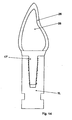
- a connecting pin 17 of a gingiva former 23 is used, as shown in Fig. 8.
- the fastening principle is the same as in the closure cap 15.
- a gingiva former 23 is conceivable in which the clip elements engage in the upper annular groove 14o.
- Fig. 9 shows a gingiva former with slit, which finds use in transgingival healing of the implant.
- FIG. 10 shows a laboratory implant 1 L into which a blank 24 of a provisional replacement tooth is likewise inserted by means of a connecting pin 17.
- the blank 24 is frusto-conical and widens, starting from the end face 5L of the laboratory implant 1 L, at an angle a of 15. In this way, misalignments of the implant 1 or 1 L compared to the adjacent teeth in wide angular ranges in all directions can be compensated.
- the connecting pin 17 of the blank 24 is also provided with clip elements 20, which ensure an uncomplicated fixing and removal of the blank 24.
- Fig. 11 shows a finished provisional replacement tooth 25, which was made by machining the blank 24 in a dental laboratory. On the ground blank, an outer ceramic layer 26 is fired.
- the finished provisional replacement tooth 25 can then be introduced into the implant 1 in the patient and fixed there with the aid of the clip elements 20 until the patient can be supplied with the final replacement tooth 28 (FIG. 12).
- This final replacement tooth 28, like the provisional replacement tooth 25, is made from a frusto-conical blank 27 (FIG. 13) in its head portion which allows for skew correction in all directions over wide angular ranges.
- the connecting pin 17 'derend claimeden replacement tooth 28 and the blank 27 has no clip elements, but is-apart from the region of the curves of the cross-sectional shape of the receiving recess 10 over the entire length of the connecting pin 17' adapted. Due to the annular grooves 13 in the wall 12 of the receiving recess 10, the connecting pin 17 can be introduced without problems until the end face of the head portion of the blank 27 comes to rest on the end face 51-of the laboratory implant 1 L.
- the termination of the restoration is that the final replacement tooth 28 is removed from the laboratory implant 1 L and inserted into the implant 1 located in the jawbone.
- the two contact surfaces 5 and 18 are frictionally against each other. Also between the outer lateral surfaces of the connecting pin 17 and the wall 12 of the receiving recess 10 is a frictional connection, which is made with the aid of adhesive or cement or formed in the case of a shrink connection by clamping forces.
- the lateral surface 29 of the connecting pin 17 'and the contact surface 18 of the head part are coated with a suitable adhesive or cement which essentially completely fills the annular grooves 13 in the receiving recess 10 when the connecting pin 17' is inserted.
- a suitable adhesive or cement which essentially completely fills the annular grooves 13 in the receiving recess 10 when the connecting pin 17' is inserted.
- Another non-positive connection is via the contact surfaces 5 and 18, wherein the adhesive is preferably applied in this area only so thin that the surface roughness of the contact surfaces are filled and it comes despite the adhesive to a material contact implant / replacement tooth. In any case, a protrusion of adhesive to the side of the contact surfaces 5 and 18 is to be avoided.
- connection between the replacement tooth 28 and the implant 1 can be further improved, even if in the lateral surface of the connecting pin 17 "a plurality of annular grooves 13" is present, which correspond to the annular grooves 13 in the wall 12 of the receiving recess 10.
- FIG. 16 Such a configuration is shown in FIG. 16.
- circular or oval-shaped adhesive rings are formed in cross section, which produce a positive connection between the replacement tooth 28 and the implant 1.
Abstract
Description
Die Erfindung betrifft ein Implantat zur Aufnahme eines Verbindungszapfens eines medizinischen Elements, mit einer Längsachse, einem distalen Ende und einem proximalen Ende, von dem aus sich eine Aufnahmeausnehmung für den Verbindungszapfen in das Innere des Implantats erstreckt, wobei das Implantat an seiner äusseren Mantelfläche kraft- oder formschlüssig mit der inneren Mantelfläche einer Aufnahmebohrung in einem Knochen eines menschlichen oder tierischen Körpers verbindbar ist, wobei der an die Aufnahmeausnehmung angepasste Verbindungszapfen in dieser durch Klemmung, Schrumpfung, Klebung oder Zementierung verankerbar ist, wobei das medizinische Element im verankerten Zustand mit einer Kontaktfläche eines in seinem Querschnitt über den Querschnitt der Aufnahmeausnehmung am proximalen Ende des Implantats radial nach aussen vorstehenden Kopfteils vollflächig an einer zugeordneten Kontaktffäche des Implantats an dessen proximalem Ende anliegt und die Aussenkontur des Querschnitts der Aufnahmeausnehmung zumindest in einem Abschnitt nicht kreisförmig ist.The invention relates to an implant for receiving a connecting pin of a medical element, having a longitudinal axis, a distal end and a proximal end, from which a receiving recess for the connecting pin extends into the interior of the implant, wherein the implant on its outer circumferential surface kraft-. or positively connected to the inner circumferential surface of a receiving bore in a bone of a human or animal body, wherein the adapted to the receiving recess connecting pin is anchored in this by clamping, shrinking, gluing or cementing, wherein the medical element in the anchored state with a contact surface of a in its cross section over the cross section of the receiving recess at the proximal end of the implant radially outwardly projecting head part over its entire surface against an associated contact surface of the implant at its proximal end and the outer contour of the Querschn itts the receiving recess is not circular at least in one section.
Derartige Implantatsysteme sind beispielsweise im zahnmedizinischen Bereich weit verbreitet.Such implant systems are widely used, for example, in the dental field.
In diesem Fall wird das aufzunehmende medizinische Element z. B. von einem Ersatzzahn, einer Verschlusskappe oder einem Gingiva-Former gebildet. Das Implantat wird beispielsweise in den Kieferknochen eingeschraubt.In this case, the male medical element z. B. formed by a replacement tooth, a cap or a gingiva former. The implant is screwed into the jawbone, for example.
Ein Implantatsystem der eingangs beschriebenen Art ist beispielsweise aus der US 5,961,328 bekannt. Der Verbindungszapfen des medizinischen Elements und die Aufnahmeausnehmung des Implantats wirken nach einem Schlüssel-Schloss-Prinzip zusammen, wobei eine Verdrehsicherheit mit Hilfe von radial über den Verbindungszapfen vorstehenden Verschlusselementen erreicht wird, die im eingesetzten Zustand des medizinischen Elements in darin angepasste Vertiefungen im Kopfteil des Implantats eingreifen. Die Aufnahmeausnehmung weist ausgehend von dem proximalen Ende des Implantats zunächst einen konischen Abschnitt auf, an den sich ein zylindrischer Abschnitt anschliesst, dessen Querschnitt dem Querschnitt am Ende des konischen Abschnitts entspricht. Der in die Aufnahmeausnehmung einzusetzende Verbindungszapfen des medizinischen Elements weist eine sich im Querschnitt in Richtung auf sein distales Ende hin verjüngende Form auf, wobei die Aussenkontur des Verbindungszapfens in einem Längsschnitt konkav verläuft und eine sägezahnartige Oberflächenstruktur besitzt. Der Querschnitt des Verbindungszapfens ist jedoch nicht kreisförmig, sondern vielmehr fehlt im Vergleich zu einer rotationssymmetrischen Gestaltung einseitig ein Längsstreifen, so dass sich ein ebener Flächenabschnitt der Mantelfläche bildet, der parallel zur Längsachse des Verbindungszapfens verläuft.An implant system of the type described above is known for example from US 5,961,328. The connecting pin of the medical element and the receiving recess of the implant cooperate according to a key-lock principle, wherein a security against rotation by means of radially above the connecting pin projecting closure elements is achieved, which in the inserted state of the medical element in it adapted recesses in the head part of the implant intervention. Starting from the proximal end of the implant, the receiving recess initially has a conical section, adjoined by a cylindrical section whose cross section corresponds to the cross section at the end of the conical section. The connecting pin of the medical element to be inserted into the receiving recess has a cross section in the direction of distal end toward tapered shape, wherein the outer contour of the connecting pin is concave in a longitudinal section and has a sawtooth-like surface structure. However, the cross-section of the connecting pin is not circular, but rather lacks in comparison to a rotationally symmetrical design on one side a longitudinal strip, so that a flat surface portion of the lateral surface forms, which is parallel to the longitudinal axis of the connecting pin.
Zum einen ist die Herstellung dieses bekannten Implantatsystems sehr aufwendig und daher teuer und zum anderen ist die Art der Krafteinleitung in den sich an das Kopfteil des medizinischen Elements anschliessenden konischen Abschnitt nicht optimal. Aufgrund der sich verjüngenden Querschnittsform ist nämlich die Möglichkeit, quer zur Längsachse des Verbindungszapfens gerichtete Kräfte, die insbesondere bei einer einseitigen Belastung des medizinischen Elements entstehen, aufzunehmen, eingeschränkt, wodurch es im ungünstigen Fall zu Kippbewegungen des medizinischen Elements kommen kann.On the one hand, the production of this known implant system is very complicated and therefore expensive and, on the other hand, the type of introduction of force into the conical section adjoining the head part of the medical element is not optimal. Because of the tapered cross-sectional shape namely the ability to transversely directed to the longitudinal axis of the connecting pin forces that arise especially in a one-sided load of the medical element, limited, which may lead to tilting movements of the medical element in an unfavorable case.
Der aus der WO99/29255 bekannte Ersatzzahn besteht aus einem Verbindungszapfen mit einem Unterteil, einem Zentralteil und einem Oberteil sowie, einer auf das Oberteil aufgeschobenen Krone. Der Ersatzzahn wird als Ganzes mit seinem konischen Unterteil in eine daran angepasste, ebenfalls konische Aufnahmebohrung in einem Implantat, das zuvor in den Kieferknochen eingesetzt und darin ausreichend eingeheilt sein muss, eingesetzt. Bei der Verbindung zwischen dem Verbindungszapfen und der Aufnahmebohrung kommt das Prinzip eines Klemmkonus zur Anwendung. Die Möglichkeit einer Verdrehung des Ersatzzahns um die Längsachse des Verbindungszapfens erlaubt es zwar, die Winkelstellung des Ersatzzahns in bezug auf eine Rotation um seine Hochachse beim Vorgang des Einsetzens exakt anzupassen, führt jedoch zu dem Nachteil, dass insbesondere bei einer grösseren Belastung eine hinreichende Verdrehsicherheit des Ersatzzahns in dem Implantat nicht gewährleistet sein kann.The replacement tooth known from WO99 / 29255 consists of a connecting pin with a lower part, a central part and an upper part, and a crown pushed onto the upper part. The replacement tooth is used as a whole with its conical lower part in an adapted, also conical receiving bore in an implant that has previously been inserted into the jawbone and must be sufficiently healed therein. In the connection between the connecting pin and the receiving bore, the principle of a clamping cone is used. The possibility of rotation of the replacement tooth about the longitudinal axis of the connecting pin, although it allows to exactly adjust the angular position of the replacement tooth with respect to a rotation about its vertical axis during the insertion process, but leads to the disadvantage that, especially at a greater load sufficient security against rotation Replacement tooth in the implant can not be guaranteed.
Alternativ zu den vorgenannten Implantatsystemen ist eine Schraubverbindung zwischen dem Ersatzzahn und dem Implantat die am weitesten verbreitete Konnektierungsart, die sich durch ihre einfache Reversibilität auszeichnet. Als Nachteil ist jedoch hier der grosse Zeitaufwand für das Eindrehen der Befestigungsschrauben, insbesondere bei einer grösseren Anzahl von Ersatzzähnen sowie die oftmals unbefriedigende Dauerhaltbarkeit derartiger Systeme anzusehen. Fertigungsbedingt weisen nämlich nie sämtliche Gewindegänge der Schraubverbindung dasselbe Tragverhalten auf, weshalb es in einzelnen Abschnitten zu einer erhöhten und in anderen Abschnitten zu einer erniedrigten Kraft- bzw. Momentenübertragung kommt. Aus diesem Grunde entstehen undefinierte Belastungszustände, aus denen ungewollte Verformungen und Spannungsspitzen resultieren können. Entweder kann es hierdurch zur Beschädigung der Schraubverbindung oder aber zu einer Oberlastung der Verbindung zwischen Implantat und Knochen kommen, was schlimmstenfalls zu einem Totalverlust des Implantats führen kann.As an alternative to the aforementioned implant systems, a screw connection between the replacement tooth and the implant is the most widespread type of connection, which is characterized by its simple reversibility. The disadvantage, however, is the large amount of time required for screwing in the fastening screws, especially for a larger number of replacement teeth and the often unsatisfactory durability of such systems. For manufacturing reasons, never all threads of the screw on the same bearing behavior, which is why it comes in individual sections to an increased and in other sections to a reduced force or torque transmission. For this reason arise undefined load conditions, which can result in unwanted deformations and voltage spikes. Either this can lead to damage to the screw connection or overloading of the connection between implant and bone, which in the worst case can lead to a total loss of the implant.
DE4127839A1 betrifft eine Vorrichtung zum Befestigen von Zahnersatz an einem Implantat, wobei das Halteteil in das Implantat (1) in unterschiedlichen Drehwinkelstellungen formschlüssig einsetzbar ist. Das Halteteil kann insbesondere mit einem Mehrkantabschnitt in einer entsprechend ausgebildeten, abgesetzten Mehrkantaufnahme im Implantat in unterschiedlichen Drehwinkelstellungen einsetzbar sein, wobei ein im Anschluss an den Mehrkantabschnitt angeformtes Retentionsteil in eine Matrize des Implantates eingreift. Die Endbefestigung wird nicht näher erläutert.DE4127839A1 relates to a device for fixing dentures on an implant, wherein the holding part in the implant (1) can be positively inserted in different rotational angle positions. The holding part can be used in particular with a polygonal section in a correspondingly formed, offset polygonal receptacle in the implant in different rotational angle positions, wherein a molded after the polygonal section retention part engages in a die of the implant. The final attachment is not explained in detail.
US5246370 beschreibt ein Implantatsystem, bei dem das Abutment in eine trichterförmige Ausnehmung am Implantatpfosten paßt und dort festgeschraubt wir.US5246370 describes an implant system in which the abutment fits into a funnel-shaped recess on the implant post and screwed there we.
Der Erfindung liegt die Aufgabe zugrunde, ein Implantatsystem vorzuschlagen, bei dem sich die Verbindung zwischen dem medizinischen Element und dem Implantat auf einfache Weise herstellen lässt, wobei die Verbindung sich durch eine gleichmässige grossflächige Krafteinleitung sowie eine Verdrehsicherung auszeichnen soll.The invention has for its object to propose an implant system in which the connection between the medical element and the implant can be produced in a simple manner, the compound should be characterized by a uniform large-scale introduction of force and a rotation.
Ausgehend von einem Implantat der eingangs beschriebenen Art wird diese Aufgabe erfindungsgemäss dadurch gelöst, dass die Aufnahmeausnehmung ausgehend von dem proximalen Ende des Implantats einen zylindrischen Abschnitt besitzt, an den sich ein sich im Querschnitt verjüngender Abschnitt anschließt 7 und dass der Verbindungszapfen ausgehend von dem Kopfteil des medizinischen Elements ebenfalls einen zylindrischen Abschnitt aufweist, an den sich ein sich im Querschnitt verjüngender Abschnitt anschliesst.Based on an implant of the type described above, this object is achieved in that the receiving recess, starting from the proximal end of the implant has a cylindrical portion, followed by a tapered in
Die vollflächige Anlage im Bereich der Kontaktflachen bewirkt eine gleichmäßige Krafteinleitung von dem medizinischen Element in das Implantat, wodurch Spannungsspitzen und damit Materialüberlastungen und -schädigungen vermieden werden. Insbesondere bewirkt der zylindrische Abschnitt des Verbindungszapfens in Verbindung mit dem angepassten zylindrischen Abschnitt des Aufnahmeausnehmung eine sichere Fixierung, bei der auch eine extrem seitliche Krafteinleitung in das medizinische Element nicht zu Zugkraftkomponenten in der Trennfläche zwischen dem medizinischen Element und der inneren Mantelfläche des Implantats führen. Die Sicherheit gegen Lösen und Herausfallen ist bei dem erfindungsgemässen Implantat daher besonders gross, unabhängig davon, ob das medizinische Element eingeschrumpft, eingeklebt oder einzementiert wird.The full-surface contact area causes uniform force transmission from the medical element into the implant, which avoids voltage peaks and thus material overloads and damage. In particular, the cylindrical portion of the connecting pin in conjunction with the adapted cylindrical portion of the receiving recess causes a secure fixation in which also an extremely lateral force introduction into the medical element do not lead to tensile force components in the interface between the medical element and the inner circumferential surface of the implant. The security Against loosening and falling out is therefore particularly large in the inventive implant, regardless of whether the medical element is shrunk, glued or cemented.
Der nicht kreisförmige Querschnitt, der beispielsweise die Form eines (abgerundeten) Polygons (Dreieck, Viereck, Fünfeck usw.) oder einer Ellipse oder eines Ovals oder eines beliebigen anderen Flächengebildes haben kann, verhindert, dass eine Drehung des Verbindungszapfens des medizinischen Elements um seine Längsachse möglich ist. Durch die eindeutig definierte Winkelposition des medizinischen Elements in bezug auf eine Rotation um die Hochachse erübrigt sich ausserdem eine aufwendige Einstellung der Position des medizinischen Elements während des Einsetzens. Die eigentliche Verbindung zwischen Implantat und Verbindungszapfen erfolgt durch Klemmung, Schrumpfung, Verklebung oder Zementierung.The non-circular cross-section, which may, for example, be in the shape of a (rounded) polygon (triangle, quadrilateral, pentagon, etc.) or an ellipse or oval or any other sheet, prevents rotation of the medical element connecting pin about its longitudinal axis is possible. Due to the clearly defined angular position of the medical element with respect to a rotation about the vertical axis also eliminates a complicated adjustment of the position of the medical element during insertion. The actual connection between implant and connecting pin is made by clamping, shrinking, gluing or cementing.
Gemäss einer Ausgestaltung der Erfindung wird vorgeschlagen, dass die in Richtung der Längsachse des Implantats gemessene Länge des zylindrischen Abschnitts des Verbindungszapfens geringfügig kleiner als die ebenfalls in Richtung der Längsachse des Implantats gemessene Länge des zylindrischen Abschnitts der Aufnahmeausnehmung ist. Hierdurch kann eine sichere Anlage der Kontaktflächen des medizinischen Elements einerseits und des Implantats andererseits erreicht werden, was für eine gleichmässige und grossflächige Krafteinfeitung wesentlich ist.According to one embodiment of the invention, it is proposed that the length of the cylindrical section of the connecting pin measured in the direction of the longitudinal axis of the implant is slightly smaller than the length of the cylindrical section of the receiving recess which is likewise measured in the direction of the longitudinal axis of the implant. In this way, a secure contact of the contact surfaces of the medical element on the one hand and the implant on the other hand can be achieved, which is essential for a uniform and large-scale power line.
Die Differenz in den Längen sollte so bemessen sein, dass unter Berücksichtigung der Fertigungstoleranzen der einzelnen Elemente auch im ungünstigsten Fall stets eine Anlage im Bereich der Kontaktflächen eintritt. Eine zu grosse Wahl der Längsdifferenz sollte jedoch vermieden werden, um im Bereich der sich verjüngenden Querschnitte unnötig grosse Spalte zwischen dem Verbindungszapfen und der Aufnahmeausnehmung zu vermeiden.The difference in the lengths should be such that, taking into account the manufacturing tolerances of the individual elements, even in the worst case, a system always occurs in the area of the contact surfaces. Too large a choice of the longitudinal difference should be avoided, however, in order to avoid unnecessarily large gaps between the connecting pin and the receiving recess in the region of the tapered cross sections.
Eine besonders vorteilhafte Ausgestaltung ist darin zu sehen, dass die Kontaktfläche kreisringförmig ist und in einer Ebene senkrecht zu der Längsachse des Implantats verläuft. Mit Hilfe einer solchen Ausgestaltung lässt sich der Aufwand bei der Herstellung des Implantats besonders gering halten. Um beim Einsetzen des Verbindungszapfens in die Aufnahmeausnehmung einen die Einschubbewegung unter Umständen behindernden Druckaufbau zu vermeiden, ist zwischen dem Verbindungszapfen in dessen verankertem Zustand und der Wandung der Aufnahmeausnehmung mindestens ein Entlüftungskanal gebildet, der sich von einer distalen Stirnseite des Verbindungszapfens bis zu dem proximalen Ende des Implantats erstreckt.A particularly advantageous embodiment is the fact that the contact surface is annular and extends in a plane perpendicular to the longitudinal axis of the implant. With the help of such a configuration, the effort in the production of the implant can be kept very low. In order to prevent the insertion movement under certain circumstances hindering pressure build-up when inserting the connecting pin into the receiving recess, at least one vent channel is formed between the connecting pin in its anchored state and the wall of the receiving recess, extending from a distal end side of the connecting pin to the proximal end of the Implant extends.
Besonders vorteilhaft ist es, wenn in der Kontaktfläche des Implantats mindestens eine Entlüftungsnut vorhanden ist, die sich von einem Entiüftungskanal bis zu der Mantelfläche des Implantats erstreckt. Auf diese Weise wird ein völlig ungehinderter Abfluss der von dem Verbindungszapfen verdrängten Luft gewährleistet.It is particularly advantageous if at least one venting groove is present in the contact surface of the implant, which extends from a venting channel to the outer surface of the implant. In this way, a completely unhindered outflow of air displaced by the connecting pin is ensured.
Sinnvollerweise wird der Verbindungszapfen im Vergleich zur der Aufnahmebohrung so dimensioniert, dass der Verbindungszapfen auf jeden Fall so weit in die Aufnahmeausnehmung eingeführt werden kann, bis die Kontaktfläche seines Kopfteils an der Kontaktfläche des Implantats vollflächig zur Anlage kommt.It makes sense that the connecting pin is dimensioned in comparison to the receiving bore so that the connecting pin can be inserted so far into the receiving recess in any case until the contact surface of its head part comes to rest on the contact surface of the implant over its entire surface.
Eine Weiterbildung des erfindungsgemässen Implantats besteht darin, dass die Wandung der Aufnahmeausnehmung mit einer Mehrzahl von Ringnuten, die jeweils in Ebenen senkrecht zur Längsachse des Implantats verlaufen, oder mit einer wendelförmigen Nut versehen ist. Die Ringnuten bzw. die wendelförmige Nut sorgen zum einen dafür, dass der Montagevorgang, insbesondere in seiner letzten Phase, erleichtert wird. Insbesondere wird ein Ansprengen der zur Anlage aneinandergelangenden Flächen verhindert und eine bessere Führung des Verbindungszapfens erreicht. Ausserdem wird in den Ringnuten bzw. in der wendelförmigen Nut bei einer Fixierung des Verbindungszapfens mit Hilfe von Klebstoff, Klebstoffringen usw. ein wendelförmiger Klebstoffwulst erzeugt, über den Axialkräfte aufgenommen werden können.A development of the implant according to the invention consists in that the wall of the receiving recess is provided with a plurality of annular grooves, each extending in planes perpendicular to the longitudinal axis of the implant, or with a helical groove. On the one hand, the annular grooves or the helical groove ensure that the assembly process, in particular in its last phase, is facilitated. In particular, a wringing of abutting surfaces for abutment is prevented and a better guidance of the connecting pin is achieved. In addition, in the annular grooves or in the helical groove in a fixation of the connecting pin by means of adhesive, adhesive rings, etc., a helical bead of adhesive is generated, can be absorbed via the axial forces.
Die Erfindung weiterausgestaltend, wird vorgeschlagen, dass die Wandung der Aufnahmeausnehmung mit mindestens einer Vertiefung versehen ist, mit der ein elastisches Clipelement eines medizinischen Elements, das heisst z. B. einer Verschlusskappe, eines Gingiva-Forrners, eines Abdruckpfostens und/oder eines provisorischen Ersatzzahns formschlüssig in Eingriff bringbar ist. Hierdurch können sämtliche Bauteile, die nur vorübergehend mit dem Implantat verbunden werden müssen, auf einfachste Weise in die Aufnahmeausnehmung eingesetzt und dadurch in einer genau vorbestimmten Position mit dem Implantat konnektiert werden. Mit dem Clipelement wird eine durch entsprechende Axialkraft wieder aufhebbare formschlüssige Verbindung geschaffen, weshalb die Clipmengen vorteilhafterweise leicht abgerundet sind, um ein zerstörungsfreies Trennen zu ermöglichen. Die Kraftübertragung erfolgt in der Übergangszeit über die Stirnflächen. Der Zeitaufwand für das Herstellen der Verbindung zwischen den nur vorübergehend verwendeten Bauteilen und dem Implantat wird drastisch reduziert, was sich insbesondere bei der gleichzeitigen Versorgung einer Mehrzahl von Implantaten in einem nicht unerheblichen Zeitgewinn äussert.The invention weiterausgestaltend, it is proposed that the wall of the receiving recess is provided with at least one recess with which an elastic clip element of a medical element, that is z. B. a cap, a gingiva Forrners, an impression post and / or a provisional replacement tooth can be brought into positive engagement. As a result, all components that need only be temporarily connected to the implant, used in the simplest way in the receiving recess and thereby be connected in a precisely predetermined position with the implant. The clip element creates a positive connection which can be reversed again by means of a corresponding axial force, which is why the clip quantities are advantageously slightly rounded in order to permit non-destructive separation. The power transmission takes place in the transitional period via the end faces. The time required for establishing the connection between the components used only temporarily and the implant is drastically reduced, which manifests itself in particular in the simultaneous supply of a plurality of implants in a significant time gain.
Beim erfindungsgemässsen Implantats besitzt der Querschnitt der Aufnahmeausnehmung in der Nähe des proximalen Endes des Implantats die Form eines abgerundeten Rechtecks und in der Nähe ihres Grundes die Form eines abgerundeten Quadrats, wobei der Übergang zwischen den vorgenannten Querschnittsformen ohne Sprünge erfolgt. Sinnvollerweise entspricht dabei die kürzere Kantenlänge des Rechtecks der Kantenlänge des Quadrats.In the case of the implant according to the invention, the cross-section of the receiving recess in the vicinity of the proximal end of the implant has the shape of a rounded rectangle and in the vicinity of its base the shape of a rounded square, the transition between the aforementioned cross-sectional shapes taking place without jumps. It makes sense that the shorter edge length of the rectangle corresponds to the edge length of the square.
Nach der Erfindung wird des weiteren ein medizinisches Element vorgeschlagen, das mit einer Kontaktfläche eines in seinem Querschnitt über den Querschnitt der Aufnahmeausnehmung am proximalen Ende radial nach aussen vorstehenden Kopfteils vollflächig an einer zugeordneten Kontaktfläche des Implantats an dessen proximalen Ende anliegt und bei dem die Aussenkontur des Querschnitts des Verbindungszapfens zumindest in einem Abschnitt nicht kreisförmig ist.According to the invention, furthermore, a medical element is proposed which, with a contact surface of a cross section over the cross section of the receiving recess at the proximal end radially outwardly projecting head portion over the entire surface of an associated contact surface of the implant at its proximal end and in which the outer contour of the Cross-section of the connecting pin is not circular at least in one section.
Hierdurch wird auf einfachste Weise eine Verdrehsicherung erzielt und die Aufnahme auch grösserer Drehmomente ermöglicht, ohne dass die Verbindung gefährdet würde. Es besteht somit die Möglichkeit, das Implantat z. B. zusammen mit einer vormontierten Verschlusskappe oder einem Gingiva-Former in den Knochen einzusetzen.As a result, an anti-rotation is achieved in the simplest way and allows the recording of larger torques without the connection would be compromised. There is thus the possibility of the implant z. B. to use together with a pre-assembled cap or a gingiva former in the bone.
Bei einer vorteilhaften Ausgestaltung besitzt der Verbindungszapfen in der Nähe seines proximalen Endes einen Querschnitt in Form eines Rechtecks, dessen Ecken stärker abgerundet oder gebrochen als die des Rechtecks des Querschnitts der Aufnahmeausnehmung an der im verankerten Zustand zugeordneten Stelle sind, und in der Nähe seines distalen Endes einen Querschnitt in Form eines abgerundeten Quadrats, dessen Ecken stärker abgerundet sind als die des Quadrats des Querschnitts der Aufnahmeausnehmung an der im verankerten Zustand zugeordneten Stelle.In an advantageous embodiment, the connecting pin has in the vicinity of its proximal end a cross-section in the form of a rectangle whose corners are more rounded or broken than those of the rectangle of the cross-section of the receiving recess in the anchored state associated body, and in the vicinity of its distal end a cross-section in the form of a rounded square, whose corners are more rounded than that of the square of the cross-section of the receiving recess at the assigned position in the anchored state.
Des weiteren wird vorgeschlagen, dass das distale Ende des Verbindungszapfens mindestens ein axial vorstehendes Clipelement aufweist, das im Einbauzustand mit einer Vertiefung in der Aufnahmeausnehmung des Implantats formschlüssig in Eingriff bringbar ist. Der Zeitaufwand bei der Montage fasst sich hierdurch gegenüber Schraubverbindungen bzw. provisorischen Klebe- bzw. Zementverbindungen erheblich reduzieren.Furthermore, it is proposed that the distal end of the connecting pin has at least one axially projecting clip element, which in the installed state can be brought into positive engagement with a recess in the receiving recess of the implant. The time required for assembly summarizes this by significantly reducing screw or provisional adhesive or cement joints.
Die formschlüssige Verbindung über das Clipelement fasst sich auf besonders einfache Weise wieder aufheben, wenn ein im Einbauzustand ausserhalb der Aufnahmeausnehmung befindlicher Abschnitt in seiner Mantelfläche mit mindestens zwei gegenüberliegenden Vertiefungen versehen ist. In diese Vertiefungen lassen sich beispielsweise hakenförmige Kontaktelemente eines zangenförmigen Werkzeugs einbringen, mit dem sich z. B. eine eingeclipste Verschlusskappe, ein eingeclipster Gingiva-Former, Abdruckpfosten und/oder provisorischer Ersatzzahn auf einfache Weise durch Aufbringung einer entsprechenden Axialkraft wieder aus dem Implantat entfernen lassen.The positive connection via the clip element summarizes itself in a particularly simple manner cancel again if a section located in the installed state outside of the receiving recess is provided in its lateral surface with at least two opposite recesses. In these depressions, for example, hook-shaped contact elements of a forceps-shaped tool can be introduced with which z. As a clipped cap, a clipped gingiva former, impression posts and / or provisional replacement tooth can be easily removed by applying a corresponding axial force again from the implant.
Die Herstellung eines Formschlusses zwischen dem Werkzeug zum Entfernen der Verschlusskappe, des Gingiva-Formers, des Abdruckpfostens und/oder des provisorischen Ersatzzahns lässt sich vereinfachen, wenn die Vertiefungen eine Ringnut mit einem V-förmigen Querschnitt bilden.The production of a positive connection between the tool for removing the closure cap, the gingiva former, the impression post and / or the provisional replacement tooth can be simplified if the depressions form an annular groove with a V-shaped cross section.
Die Erfindung weiterausgestaltend, ist bei einem endgültigen Ersatzzahn vorgesehen, dass die Mantelfläche des Verbindungszapfens mit einer Mehrzahl von Ringnuten, die jeweils in einer Ebene senkrecht zur Längsachse des Verbindungszapfens verlaufen, versehen ist, die im verankerten Zustand des Ersatzzahns mit den Ringnuten in der Wandung der Aufnahmeausnehmung korrespondieren.The invention further refinement, it is provided in a final replacement tooth, that the lateral surface of the connecting pin with a plurality of annular grooves, each extending in a plane perpendicular to the longitudinal axis of the connecting pin, provided in the anchored state of the replacement tooth with the annular grooves in the wall of the Receiving recess correspond.
Die Erfindung wird nachfolgend anhand eines Ausführungsbeispiels, das in der Zeichnung dargestellt ist, näher erläutert.The invention will be explained in more detail with reference to an embodiment which is illustrated in the drawing.
Es zeigt :
- Fig. 1
- ein Implantat mit einer eingeclipsten Verschlusskappe im Längsschnitt;
- Fig. 2
- eine Draufsicht auf die Verschlusskappe;
- Fig. 3
- eine Draufsicht auf das Implantat nach Entfernung der Verschlusskappe;
- Fig. 4
- einen Querschnitt entlang der Linie IV-IV durch das Implantat gemäss Fig. 1;
- Fig. 5
- einen Querschnitt entlang der Linie V-V durch das Implantat gemäss Fig. 1;
- Fig. 6
- einen vergrösserten Ausschnitt des Eingriffsbereichs eines Clipelements;
- Fig. 7
- einen vergrösserten und prinziphaft dargestellten Ausschnitt vom unterschiedlichen Beginn der Querschnittsverjüngung des Implantats und des Verbindungszapfens;
- Fig. 8
- wie Fig. 1, jedoch mit aufgeclipstem Gingiva-Former;
- Fig. 9
- wie Fig. 8, jedoch mit Schlitz im Gingiva-Former für transgingivale Einheilung;
- Fig. 10
- einen Rohling für einen provisorischen Ersatzzahn in einem Laborimplantat;
- Fig. 11
- wie Fig. 10, jedoch eines fertigen provisorischen Ersatzzahns;
- Fig. 12
- wie Fig. 11, jedoch im erfindungsgemässen Implantat;
- Fig. 13
- wie Fig. 10, jedoch eines endgültigen Ersatzzahns;
- Fig. 14
- wie Fig. 11, jedoch eines endgültigen Ersatzzahns;
- Fig. 15
- wie Fig. 12, jedoch eines endgültigen Ersatzzahns und
- Fig. 16
- wie Fig. 15, jedoch mit einem Verbindungszapfen mit Ringnuten in der Mantelfläche.
- Fig. 1
- an implant with a clipped cap in longitudinal section;
- Fig. 2
- a plan view of the closure cap;
- Fig. 3
- a plan view of the implant after removal of the cap;
- Fig. 4
- a cross section along the line IV-IV through the implant according to FIG. 1;
- Fig. 5
- a cross section along the line VV through the implant according to FIG. 1;
- Fig. 6
- an enlarged section of the engagement portion of a clip element;
- Fig. 7
- an enlarged and principally illustrated section of the different beginning of the cross-sectional taper of the implant and the connecting pin;
- Fig. 8
- as in FIG. 1, but with a clipped gingiva former;
- Fig. 9
- as Fig. 8, but with a slot in the gingiva former for transgingival healing;
- Fig. 10
- a blank for a provisional replacement tooth in a laboratory implant;
- Fig. 11
- like Fig. 10, but a finished provisional replacement tooth;
- Fig. 12
- as in FIG. 11, but in the implant according to the invention;
- Fig. 13
- like Fig. 10, but a final replacement tooth;
- Fig. 14
- like Fig. 11, but a final replacement tooth;
- Fig. 15
- as Fig. 12, but a final replacement tooth and
- Fig. 16
- as Fig. 15, but with a connecting pin with annular grooves in the lateral surface.
Den Fig. 1 bis 5 lässt sich ein aus Titan bestehendes Implantat 1 entnehmen, das eine ungefähr konische äussere Grundform besitzt und an seiner äusseren Mantelfläche mit einem Aussengewinde 2 versehen ist. Das Implantat 1 besitzt ein abgerundetes distales Ende 3 und ein proximales Ende 4, das von einer im wesentlichen kreisringförmigen Kontaktfläche 5 gebildet wird. In einem an die Kontaktfläche 5 anschliessenden Abschnitt 6 besitzt das Implantat aussen eine zylindrische Form mit einer hochglanzpolierten Mantelfläche 7. In einem darauf folgenden Gewindebereich 8 ist das Implantat 1 konisch ausgeformt. Ausgehend von der Kontaktfläche 5, erstreckt sich parallel zu einer Längsachse 9 des Implantats 1 eine Aufnahmeausnehmung 10, die über die gesamte Länge des Abschnitts 6 sowie einen Teil der Länge des Gewindeabschnitts 8 verläuft.FIGS. 1 to 5 show an
Aus der Prinzipdarstellung gemäss Figur 7 ergibt sich, dass die Aufnahmeausnehmung 10 ausgehend von dem proximalen Ende 4 des Implantats 1 zunächst einen zylindrischen Abschnitt 10Z besitzt, an den sich ein sich im Querschnitt verjüngender Abschnitt 10V anschliesst. Daran angepasst weist der Verbindungszapfen 17 eines einzusetzenden Ersatzzahns ausgehend von dem Kopfteil 16 ebenfalls zunächst einen zylindrischen Abschnitt 17Z auf, dessen Durchmesser geringfügig kleiner als der Durchmesser der Aufnahmeausnehmung 10 in deren zylindrischen Abschnitt 10Z ist. An den zylindrischen Abschnitt 17Z des Verbindungszapfens 17 schliesst sich ein sich im Querschnitt verjüngender Abschnitt 17V an. Da die Länge 6a des zylindrischen Abschnitts 17Z des Verbindungszapfens 17 geringfügig kleiner als die Länge 6b des zylindrischen Abschnitts 10Z der Aufnahmeausnehmung 10 bemessen ist, ist ausgeschlossen, dass es im Bereich der sich verjüngenden Abschnitte 10V, 17V zu einer Anlage des Verbindungszapfens 17 an die Wandung 12 der Aufnahmeausnehmung 10 kommt. Vielmehr ist durch diese Art der Komponentenpassung sichergestellt, dass stets eine vollflächige Anlage der Kontaktflächen 5 und 18 am proximalen Ende des Implantats 1 erzielt wird. Die Differenz zwischen den Längen 6b und 6a, d. h. der axiale Abstand zwischen den Umlaufkanten 12a an dem Verbindungszapfen 17 und 12b an der Aufnahmeausnehmung 10 des Implantats 1 wird so bemessen, dass auch im ungünstigsten Fall der Fertigungstoleranzen stets ein Minimalabstand in den Abschnitten 10V und 17V erhalten bleibt. Ansonsten ist die Längendifferenz möglichst gering zu halten, um das Spaltmass im Bereich der sich verjüngenden Abschnitte 10V und 17V gering zu halten.7 shows that the receiving
Wie sich den Fig. 3 und 7 entnehmen lässt, besitzt der Querschnitt der Aufnahmeausnehmung 10 im Bereich des zylindrischen Abschnitts 10Z durchgängig die Form eines abgerundeten Rechtecks. Beginnend mit dem Gewindebereich 8, verjüngt sich der Querschnitt der Aufnahmeausnehmung 10 in einem folgenden Abschnitt 10V dahingehend kontinuierlich, dass am Grund 11 der Aufnahmeausnehmung 10 der Querschnitt die Form eines abgerundeten Quadrats (vgl. Fig. 5) aufweist. Im Gewindebereich 8 erfolgt der Übergang von der abgerundeten rechteckigen zur abgerundeten quadratischen Querschnittsform kontinuierlich und ohne Sprünge.As can be seen from FIGS. 3 and 7, the cross-section of the receiving
Wie sich insbesondere aus Fig. 1 erkennen fasst, ist die Wandung 12 der Aufnahmeausnehmung 10 mit einer Vielzahl von Ringnuten 13 versehen, die senkrecht zur Längsachse 9 ausgerichtet sind. Des weiteren ist die Wandung 12 mit einer oberen und einer unteren Clipnut 14o und 14u versehen, deren Funktion später anhand der Fig. 6 erläutert wird.As can be seen in particular from Fig. 1, the
In das in Fig. 1 dargestellte Implantat 1 ist eine Verschlusskappe 15 eingesetzt, die aus einem ungefähr zylinderförmigen Kopfteil 16 und einem koaxial hierzu ausgerichteten Verbindungszapfen 17 besteht, der sich in die Aufnahmeausnehmung 10 erstreckt. Eine Kontaktfläche 18 des Kopfteils 16 kommt an der Kontaktfläche 5 des Implantats 1kraftschlüssig zur Anlage.In the
Wie sich der Fig. 3 entnehmen lässt, weist der Verbindungszapfen 17 in einem oberen Abschnitt einen ungefähr rechteckförmigen Querschnitt auf, wobei die Eckbereiche derart gebrochen sind, dass in den Rundungsbereichen des Querschnitts der Aufnahmeausnehmung 10 zwischen dem Verbindungszapfen 17 und der Wandung 12 der Aufnahmeausnehmung 10 vier Entlüfungskanäle 19a gebildet werden. Beim Einschieben des Verbindungszapfens 17 in die Aufnahmeausnehmung 10 verdrängte Luft kann daher, ohne dass es zu einem den Montagevorgang behindernden Druckaufbau kommt, nach oben abgeführt werden, wobei die Luft durch vier radial nach aussen verlaufende Entlüftungsnuten 19b, die in die Stirnfläche 5 des Implantats eingebracht sind und mit den Entlüftungskanälen 19a kommunizieren, nach aussen entweichen kann.As can be seen from FIG. 3, the connecting
Da die Verschlusskappe lediglich temporär nach der Implantation an dem Implantat 1 verbleibt, ist diese lediglich mit Hilfe von vier Clipelementen 20, die in die Clipnut140 eingreifen, mit dem Implantat 1 verbunden. Anstelle des in Fig. 1 gezeigten Eingriffs der Clipelemente 20 in die obere Clipnut 14o ist bei einem entsprechend verlängerten Verbindungszapfen 17 auch ein Eingriff in die untere Clipnut 14u möglich.Since the closure cap remains only temporarily after implantation on the
Die Verschlusskappe 15 wird bereits vom Hersteller des Implantats 1 in dieses eingesetzt und dient einerseits dazu, das Implantat 1 nach Anfertigung einer entsprechenden Bohrung im Knochen mit Hilfe eines Schraubendrehers, der in den in Fig. 2 gezeigten Schlitz 21 eingreift, einzudrehen. Aufgrund des annähernd rechteckförmigen Querschnitts des Verbindungszapfens 17 und der angepassten Aufnahmeausnehmung 10 ist eine Drehmomenteinleitung über die Verschlusskappe 15 in das Implantat 1 möglich. Nach der Implantation verbleibt die Verschlusskappe 15 am Implantat 1, um zum anderen die Aufnahmeausnehmung 10 vor äusseren Verschmutzungen zu schützen.The
Circa drei bis sechs Monate nach Einsetzen des Implantats in den Kieferknochen ist die Einheilung so weit abgeschlossen, dass die die Verschlusskappe 15 abdeckende Schleimhaut in einer zweiten Operation wieder geöffnet werden kann. Die Verschlusskappe 15 wird entfernt, wozu mit Hilfe eines zangenartigen Werkzeugs in eine V-förmige Ringnut 22 in dem Kopfteil 16 eingegriffen wird und hierdurch die gesamte Verschlusskappe 15 durch einen leichten Ruck in axiale Richtung nach oben aus dem Implantat 1 entfernt wird. In die Aufnahmeausnehmung 10 des Implantats 1 wird nunmehr ein Verbindungszapfen 17 eines Gingiva-Formers 23 eingesetzt, wie er in Fig. 8 dargestellt ist. Das Befestigungsprinzip ist dasselbe wie bei der Verschlusskappe 15. Exemplarisch ist in Fig. 8 dargestellt, dass die Clipselemente 20 des Gingiva-Formers 23 in die untere Ringnut 14u einrasten. Ebenso ist jedoch ein Gingiva-Former 23 denkbar, bei dem die Clipelemente in die obere Ringnut 14o eingreifen.About three to six months after the implant has been inserted into the jawbone, the healing has been completed so far that the mucous membrane covering the
Fig. 9 zeigt einen Gingiva-Former mit Schlitz, der bei transgingivaler Einheilung des Implantats Verwendung findet.Fig. 9 shows a gingiva former with slit, which finds use in transgingival healing of the implant.
Fig. 10 zeigt ein Laborimplantat 1 L, in das ein Rohling 24 eines provisorischen Ersatzzahns ebenfalls mit Hilfe eines Verbindungszapfens 17 eingesetzt ist. Der Rohling 24 ist kegelstumpfförmig und erweitert sich, ausgehend von der Stirnfläche 5L des Laborimplantats 1 L, unter einem Winkel a von 15. Auf diese Weise lassen sich Schiefstellungen des Implantats 1 bzw. 1 L gegenüber den Nachbarzähnen in weiten Winkelbereichen in alle Richtungen ausgleichen. Der Verbindungszapfen 17 des Rohlings 24 ist ebenfalls mit Clipelementen 20 versehen, die ein unkompliziertes Fixieren und Entnehmen des Rohlings 24 gewährleisten.10 shows a
Fig. 11 zeigt einen fertigbearbeiteten provisorischen Ersatzzahn 25, der durch spanende Bearbeitung des Rohlings 24 in einem zahntechnischen Labor gefertigt wurde. Auf den geschliffenen Rohling ist eine äussere Keramikschicht 26 aufgebrannt.Fig. 11 shows a finished
Der fertige provisorische Ersatzzahn 25 kann anschliessend beim Patienten in das Implantat 1 eingeführt und dort mit Hilfe der Clipelemente 20 so lange fixiert werden, bis der Patient mit dem endgültigen Ersatzzahn 28 versorgt werden kann (Fig. 12).The finished
Dieser endgültige Ersatzzahn 28 wird wie der provisorische Ersatzzahn 25 aus einem in seinem Kopfteil kegelstumpfförmigen Rohling 27 (Fig. 13) hergestellt, der eine Schiefstellungskorrektur in alle Richtungen in weiten Winkelbereichen erlaubt. Der Verbindungszapfen 17' desendgültigen Ersatzzahns 28 bzw. dessen Rohlings 27 besitzt keine Clipelemente, sondern ist-abgesehen vom Bereich der Rundungen der Querschnittsform der Aufnahmeausnehmung 10 über die gesamte Länge des Verbindungszapfens 17' angepasst. Aufgrund der Ringnuten 13 in der Wandung 12 der Aufnahmeausnehmung 10 lässt sich der Verbindungszapfen 17 unproblematisch einführen, bis die Stirnfläche des Kopfteils des Rohlings 27 an der Stirnfläche 51-des Laborimplantas 1 L zur Anlage kommt. Unterschiedliche Anfänge der "Konizitäten" gewährleisten eine kraftschlüssige Verbindung über die Kontaktflächen 5 und 18 (s. auch Fig. 7). Ausgehend von dieser Einbauposition des Rohlings 27 im Laborimplantat 1 L kann die endgültige Form des Ersatzzahns 28, der wiederum eine aufgebrannte Keramikschicht 26 besitzt, hergestellt werden (Fig. 11).This
Der Abschuss der Versorgung besteht darin, dass der endgültige Ersatzzahn 28 aus dem Laborimplantat 1 L entfernt und in das im Kieferknochen befindliche Implantat 1 eingesetzt wird.The termination of the restoration is that the
Im Einbauzustand liegen die beiden Kontaktflächen 5 und 18 kraftschlüssig aneinander. Auch zwischen den äusseren Mantelflächen des Verbindungszapfens 17 und der Wandung 12 der Aufnahmeausnehmung 10 besteht ein Kraftschluss, der mit Hilfe von Klebstoff oder Zement hergestellt oder im Falle einer Schrumpfverbindung durch Klemmkräfte gebildet wird.In the installed state, the two
Gemäss Figur 15 werden die Mantelfläche 29 des Verbindungszapfens 17' und die Kontaktfläche 18 des Kopfteils mit einem geeigneten Klebstoff oder Zement bestrichen, der beim Einsetzen des Verbindungszapfens 17' die Ringnuten 13 in der Aufnahmeausnehmung 10 im wesentlichen vollständig ausfüllt. Nach Aushärtung des Klebstoffs existieren somit Klebstoffwulste, die auf dem Verbindungszapfen 17' anhaften und somit eine formschlüssige Verbindung mit dem Implantat 1 herstellen. Eine weitere kraftschlüssige Verbindung besteht über die Kontaktflächen 5 und 18, wobei der Klebstoff in diesem Bereich vorzugsweise nur so dünn aufgetragen wird, dass die Oberflächenrauhigkeiten der Kontaktflächen ausgefüllt werden und es trotz des Klebers zu einem Materialkontakt Implantat/Ersatzzahn kommt. Auf jeden Fall ist ein Hervorquellen von Klebstoff seitlich der Kontaktflächen 5 und 18 zu vermeiden.According to FIG. 15, the
Die Festigkeit der Verbindung zwischen dem Ersatzzahn 28 und dem Implantat 1 kann weiter verbessert werden, wenn auch in der Mantelfläche des Verbindungszapfens 17" eine Mehrzahl von Ringnuten 13"vorhanden ist, die mit den Ringnuten 13 in der Wandung 12 der Aufnahmeausnehmung 10 korrespondieren. Eine derartige Ausgestaltung ist in Fig. 16 dargestellt. Es bilden sich hierbei im Querschnitt kreisförmige bzw. ovalförmige Klebstoffringe aus, die eine formschlüssige Verbindung zwischen dem Ersatzzahn 28 und dem Implantat 1 herstellen.The strength of the connection between the
Claims (15)
- Implant system comprising• an implant• a medical devicewherein the implant (1) is provided for receiving a connecting peg (17, 17', 17") of the medical device,
wherein the implant comprises:a longitudinal axis (9), a distal end (3) and a proximal end (4), from which a receiving recess (10) for the connecting peg (17, 17', 17") extends into the interior of the implant (1), wherein the implant (1) can be connected non-positively or positively by its external surface to the internal surface of a receiving bore in a bone of a human or animal body, wherein the connecting peg (17, 17', 17") adapted to the receiving recess (10) can be anchored therein by clamping, shrinkage, adhesion or cementing, the anchored medical device rests with a contact face (18) of a top portion (16) protruding radially outwards in its cross-section beyond the cross-section of the receiving recess (10) at the proximal end (4) of the implant (1), over its entire area, on an associated contact face (5) of the implant (1) at the proximal end (4) thereof, and the external contour of the cross-section of the receiving recess (10) is not circular, at least in a portion,wherein the receiving recess (10), extending from the proximal end (4) of the implant (1), has a cylindrical portion (10Z) which is followed by a portion (10V) that tapers in cross-section, and wherein, extending from the top portion (16) of the medical device, the connecting peg (17, 17', 17") also has a cylindrical portion (17Z) which is followed by a portion (17Z) that tapers in cross-section,wherein the cross-section of the receiving recess (10), in the vicinity of the proximal end (4) of the implant (1), has the form of a rounded rectangle and, in the vicinity of its base (11), the form of a rounded square, the transition between the aforementioned cross-sectional shapes having no jumps;and wherein the medical device rests with a contact face (18) of a top portion (16) protruding radially outwards in its cross-section beyond the cross-section of the receiving recess (10) at the proximal end (4) of the implant (1), over its entire area, on an associated contact face (5) of the implant (1) at the proximal end thereof, the external contour of the cross-section of the connecting peg (17, 17', 17") is not circular, at least in a portion, and in that, extending from a top portion (16), the connecting peg (17, 17', 17") has a cylindrical portion (17Z) which is followed by a portion (17V) that tapers in cross-section. - Implant system according to claim 1, characterised in that, measured in the direction of the longitudinal axis (9) of the implant (1), the length (6a) of the cylindrical portion (17Z) of the connecting peg (17, 17', 17") is slightly less than the length (6b) of the cylindrical portion (10Z) of the receiving recess (10), also measured in the direction of the longitudinal axis (9) of the implant (1).
- Implant system according to either claim 1 or claim 2, characterised in that the contact face (5) is circular and extends in a plane perpendicular to the longitudinal axis (9) of the implant (1).
- Implant system according to any one of claims 1 to 3, characterised in that, between the anchored connecting peg (17, 17', 17") and the wall (12) of the receiving recess (10), there is formed at least one ventilation duct (19a) which extends from a distal end face of the connecting peg (17, 17', 17") to the proximal end (4) of the implant (1).
- Implant system according to claim 4, characterised in that, in the contact face (5) of the implant (1), there is provided at least one ventilation groove (19b) which extends from a ventilation duct (19a) to the surface of the implant (1).
- Implant system according to any one of claims 1 to 5, characterised in that the wall (12) of the receiving recess (10) is provided with a plurality of annular grooves (13), which each extend in planes perpendicular to the longitudinal axis (9) of the implant (1), or with a helical groove.
- Implant system according to any one of claims 1 to 6, characterised in that the wall of the receiving recess (10) is provided with at least one indentation, with which a resilient clip element (20) of a medical device can positively engage.
- Implant system according to claim 7, characterised in that the shorter edge length of the rectangle corresponds to the edge length of the square.
- Implant system according to any one of claims 1 to 8, characterised in that it is provided for receiving a replacement tooth (25).
- Implant system according to any one of claims 1 to 9, wherein, in the case of the medical device, the connecting peg (17, 17', 17"), in the vicinity of its proximal end, has a cross-section in the form of a rectangle of which the corners are rounded or broken more markedly than those of the rectangle of the cross-section of the receiving recess (10) at the position allocated when fitted and, in the vicinity of its distal end, has a cross-section in the form of a square of which the corners are rounded or broken more markedly than those of the square of the cross-section of the receiving recess at the position allocated when fitted.
- Implant system according to any one of claims 1 to 10, wherein, in the case of the medical device, the distal end of the connecting peg (17) has at least one axially protruding clip element (20) which, when fitted, can engage positively with an indentation in the receiving recess (10) of an implant (1).
- Implant system according to any one of claims 1 to 11, wherein, in the case of the medical device, a portion which is located outside the receiving recess when fitted is provided with at least two opposing indentations in its surface.
- Implant system according to any one of claims 1 to 12, wherein, in the case of the medical device, the indentations form an annular groove (22) having a V-shaped cross-section.
- Implant system according to any one of claims 1 to 13, wherein the medical device is a cap 15, a gingiva shaper (23), an impression rod and/or a replacement tooth (25).
- Implant system according to claim 14, wherein, in the case of the replacement tooth (28), the surface of the connecting peg (17") is provided with a plurality of annular grooves (13") which each extend in a plane perpendicular to the longitudinal axis of the connecting peg (17") and, when the replacement tooth (28) is anchored, correspond to the annular grooves (13) in the wall (12) of the receiving recess (10).
Applications Claiming Priority (3)
| Application Number | Priority Date | Filing Date | Title |
|---|---|---|---|
| DE10019338A DE10019338B4 (en) | 2000-04-19 | 2000-04-19 | implant |
| DE10019338 | 2000-04-19 | ||
| PCT/EP2001/003948 WO2001080768A1 (en) | 2000-04-19 | 2001-04-06 | Medical implant |
Publications (2)
| Publication Number | Publication Date |
|---|---|
| EP1274364A1 EP1274364A1 (en) | 2003-01-15 |
| EP1274364B1 true EP1274364B1 (en) | 2007-01-17 |
Family
ID=7639276
Family Applications (1)
| Application Number | Title | Priority Date | Filing Date |
|---|---|---|---|
| EP01927885A Expired - Lifetime EP1274364B1 (en) | 2000-04-19 | 2001-04-06 | Medical implant |
Country Status (17)
| Country | Link |
|---|---|
| US (1) | US6840769B2 (en) |
| EP (1) | EP1274364B1 (en) |
| JP (1) | JP3764681B2 (en) |
| CN (1) | CN1299651C (en) |
| AU (2) | AU5478601A (en) |
| BR (1) | BR0110168B1 (en) |
| CA (1) | CA2406759C (en) |
| DE (2) | DE10019338B4 (en) |
| DK (1) | DK1274364T3 (en) |
| ES (1) | ES2277921T3 (en) |
| IL (2) | IL152353A0 (en) |
| MX (1) | MXPA02010238A (en) |
| NO (1) | NO20024890D0 (en) |
| PL (1) | PL194748B1 (en) |
| PT (1) | PT1274364E (en) |
| RU (1) | RU2234285C2 (en) |
| WO (1) | WO2001080768A1 (en) |
Families Citing this family (27)
| Publication number | Priority date | Publication date | Assignee | Title |
|---|---|---|---|---|
| DE10019331B4 (en) | 2000-04-19 | 2005-09-01 | Heraeus Kulzer Gmbh | Device with a rod element and a post-shaped element |
| DE10045543A1 (en) | 2000-09-13 | 2002-03-28 | Degussa | Plug connection for jaw stump models |
| EP1506745A1 (en) * | 2003-08-15 | 2005-02-16 | Jeanette Mörmann | Blank and method for making a dental restoration |
| SE526746C2 (en) * | 2003-12-11 | 2005-11-01 | Nobel Biocare Ab | Implant applicable to dentures with associated soft tissue |
| FR2879122B1 (en) | 2004-12-15 | 2008-10-03 | Inergy Automotive Systems Res | PROCESS FOR THE MANUFACTURE OF A PLASTIC FUEL TANK HAVING IMPROVED FLOWING RESISTANCE |
| DE102005008273A1 (en) * | 2005-02-22 | 2006-08-24 | Mundorf, Sönke, Dr. | Tooth implant comprises a bone anchoring part having an outer surface for anchoring in the jawbone and formed as a tissue anchoring part and a tooth alignment part fixed to the bone anchoring part on which a crown is fixed |
| DE102005027402A1 (en) * | 2005-06-13 | 2006-12-28 | Heraeus Kulzer Gmbh | Individualized spare tooth manufacturing method for dental medical area, involves accommodating spare tooth in intake recess by connecting pin that is designed at tooth, where tooth is manufactured as one-piece |
| DE102006007233A1 (en) * | 2006-02-15 | 2007-08-16 | Hager & Meisinger Gmbh | Tooth device for bracing a tooth replacement has a base/base- plate with projecting pieces to engage in a tooth recess, a bone recess or a recess of a part anchored in a bone or tooth |
| DE102006040516A1 (en) * | 2006-08-30 | 2008-03-06 | Prokuro Gmbh | Connecting unit e.g. metal pin and connecting bolt, for mounting abutment in implant, has support unit that is provided for spring unit i.e. disc spring, at one end that is arranged in area of abutment, where disc spring has central hole |
| WO2008111068A1 (en) * | 2007-03-15 | 2008-09-18 | A.B. Dental Devices Ltd | Device providing an interface between a dental implant and an abutment |
| DE102007045154A1 (en) | 2007-09-20 | 2009-04-09 | Heraeus Kulzer Gmbh | Mixing capsule for two-component material |
| US20090298008A1 (en) * | 2008-05-29 | 2009-12-03 | Ibur, L.L.C. | Dental x-ray and drill guide apparatus and method |
| DE102008028232A1 (en) | 2008-06-16 | 2009-12-17 | Heraeus Kulzer Gmbh | Dental feed dosage |
| EP2353540A1 (en) * | 2010-01-28 | 2011-08-10 | Sudimplant | Assembly of a dental implant and a prosthetic element |
| US9585695B2 (en) | 2013-03-15 | 2017-03-07 | Woven Orthopedic Technologies, Llc | Surgical screw hole liner devices and related methods |
| US9907593B2 (en) | 2014-08-05 | 2018-03-06 | Woven Orthopedic Technologies, Llc | Woven retention devices, systems and methods |
| US8956394B1 (en) | 2014-08-05 | 2015-02-17 | Woven Orthopedic Technologies, Llc | Woven retention devices, systems and methods |
| US9943351B2 (en) | 2014-09-16 | 2018-04-17 | Woven Orthopedic Technologies, Llc | Woven retention devices, systems, packaging, and related methods |
| USD740427S1 (en) | 2014-10-17 | 2015-10-06 | Woven Orthopedic Technologies, Llc | Orthopedic woven retention device |
| BR102014031426B1 (en) | 2014-12-15 | 2018-07-24 | Jjgc Ind E Comercio De Materiais Dentarios S/A | implant |
| CL2015001657S1 (en) | 2014-12-15 | 2016-09-02 | Jjgc Indústria E Comércio De Materiais Dentários S A | Configuration applied to bone implant. |
| WO2017024277A1 (en) | 2015-08-05 | 2017-02-09 | Woven Orthopedic Technologies, Llc | Tapping devices, systems and methods for use in bone tissue |
| BR102016010184B1 (en) | 2016-05-05 | 2020-10-27 | Jjgc Indústria E Comércio De Materiais Dentários S.A. | prosthetic set and process for producing the same |
| WO2018107114A1 (en) | 2016-12-09 | 2018-06-14 | Woven Orthopedic Technologies, LLC. | Retention devices, lattices and related systems and methods |
| KR102055821B1 (en) * | 2017-09-18 | 2019-12-16 | 오스템임플란트 주식회사 | A dental implant assembly and a method for manufacturing the same |
| DE102019100016A1 (en) * | 2019-01-02 | 2020-07-02 | Aesculap Ag | Joining method for a medical device |
| CN114366354A (en) * | 2021-12-31 | 2022-04-19 | 北京劲松口腔医院投资管理有限公司 | Titanium mesh component for alveolar bone loss and manufacturing method thereof |
Family Cites Families (19)
| Publication number | Priority date | Publication date | Assignee | Title |
|---|---|---|---|---|
| DE353395C (en) * | 1922-05-16 | Magnet Werk G M B H Eisenach | Device for separating the armature from the magnet in electromagnetically operated reversing gears | |
| DE3241963C1 (en) * | 1982-11-12 | 1984-04-26 | Feldmühle AG, 4000 Düsseldorf | Helical jaw implant |
| DE3300764A1 (en) | 1983-01-12 | 1984-07-12 | Johannes Bademis | Jaw implant comprising an implant body and a mobile attachment fixable thereon |
| AT380780B (en) | 1984-09-21 | 1986-07-10 | Koinig Horst | IMPLANT |
| JPH0712365B2 (en) | 1985-04-04 | 1995-02-15 | オリンパス光学工業株式会社 | Artificial tooth root |
| DE3917690A1 (en) * | 1989-05-31 | 1990-12-13 | Kirsch Axel | ENOSSAL SINGLE TOOTH IMPLANT AND COUNTERTOOL TO USE WITH SUCH AN IMPLANT |
| US5030095A (en) * | 1989-08-16 | 1991-07-09 | Niznick Gerald A | Angled abutment for endosseous implants |
| DE4127436A1 (en) * | 1990-08-21 | 1992-03-05 | Gerold Klaus | Attaching dental prosthesis to implant - using resilient plastics bush fitted over end of fixing bolt |
| DE4127839A1 (en) * | 1990-09-01 | 1992-03-19 | Gerold Klaus | Fixing replacement tooth to implant - involves holder part insertable inimplant in varying rotary angle positions |
| DE4028857A1 (en) * | 1990-09-08 | 1992-03-12 | Eberle Medizintech Elemente | ENOSSAL IMPLANT FOR A FIXED DENTAL REPLACEMENT |
| US5197881A (en) * | 1991-12-30 | 1993-03-30 | Wellesley Research Associates, Inc. | Dental implant system and apparatus |
| US5246370A (en) * | 1992-11-27 | 1993-09-21 | Coatoam Gary W | Dental implant method |
| AT400804B (en) * | 1994-10-10 | 1996-03-25 | Mke Metall Kunststoffwaren | IMPLANT |
| US5961328A (en) * | 1995-01-23 | 1999-10-05 | Somborac; Milan | Dental implant |
| DE29605296U1 (en) * | 1996-03-21 | 1996-05-30 | Zahntechnisches Atelier Lothar | Abutment for dental superstructures |
| EP1039840A4 (en) | 1997-12-10 | 2006-10-04 | Debbie Llc | Dental implant system and method |
| US6273720B1 (en) * | 1999-04-20 | 2001-08-14 | Robert Spalten | Dental implant system |
| WO2000064384A1 (en) * | 1999-04-27 | 2000-11-02 | Steinicke Maschinen- Und Werkzeugbau Ag | Endoprosthesis, especially for an artificial hip joint |
| US6358052B1 (en) * | 1999-07-15 | 2002-03-19 | L. Paul Lustig | Dental implant system and method for effecting a dental restoration using the same |
-
2000
- 2000-04-19 DE DE10019338A patent/DE10019338B4/en not_active Expired - Fee Related
-
2001
- 2001-04-06 AU AU5478601A patent/AU5478601A/en active Pending
- 2001-04-06 WO PCT/EP2001/003948 patent/WO2001080768A1/en active IP Right Grant
- 2001-04-06 CN CNB018082483A patent/CN1299651C/en not_active Expired - Fee Related
- 2001-04-06 DE DE50111900T patent/DE50111900D1/en not_active Expired - Lifetime
- 2001-04-06 EP EP01927885A patent/EP1274364B1/en not_active Expired - Lifetime
- 2001-04-06 RU RU2002130826/14A patent/RU2234285C2/en not_active IP Right Cessation
- 2001-04-06 PL PL01357951A patent/PL194748B1/en not_active IP Right Cessation
- 2001-04-06 DK DK01927885T patent/DK1274364T3/en active
- 2001-04-06 JP JP2001577871A patent/JP3764681B2/en not_active Expired - Fee Related
- 2001-04-06 BR BRPI0110168-4A patent/BR0110168B1/en not_active IP Right Cessation
- 2001-04-06 MX MXPA02010238A patent/MXPA02010238A/en active IP Right Grant
- 2001-04-06 CA CA002406759A patent/CA2406759C/en not_active Expired - Fee Related
- 2001-04-06 IL IL15235301A patent/IL152353A0/en active IP Right Grant
- 2001-04-06 AU AU2001254786A patent/AU2001254786B2/en not_active Ceased
- 2001-04-06 ES ES01927885T patent/ES2277921T3/en not_active Expired - Lifetime
- 2001-04-06 US US10/257,926 patent/US6840769B2/en not_active Expired - Fee Related
- 2001-04-06 PT PT01927885T patent/PT1274364E/en unknown
-
2002
- 2002-10-10 NO NO20024890A patent/NO20024890D0/en not_active Application Discontinuation
- 2002-10-17 IL IL152353A patent/IL152353A/en not_active IP Right Cessation
Also Published As
| Publication number | Publication date |
|---|---|
| CA2406759C (en) | 2007-07-17 |
| EP1274364A1 (en) | 2003-01-15 |
| ES2277921T3 (en) | 2007-08-01 |
| US6840769B2 (en) | 2005-01-11 |
| AU2001254786B2 (en) | 2006-03-30 |
| NO20024890L (en) | 2002-10-10 |
| IL152353A (en) | 2007-08-19 |
| PL357951A1 (en) | 2004-08-09 |
| DE10019338A1 (en) | 2001-11-08 |
| JP3764681B2 (en) | 2006-04-12 |
| DE10019338B4 (en) | 2007-06-06 |
| CN1424893A (en) | 2003-06-18 |
| US20030157459A1 (en) | 2003-08-21 |
| AU5478601A (en) | 2001-11-07 |
| BR0110168B1 (en) | 2010-09-21 |
| RU2234285C2 (en) | 2004-08-20 |
| MXPA02010238A (en) | 2003-04-25 |
| PL194748B1 (en) | 2007-06-29 |
| DK1274364T3 (en) | 2007-05-21 |
| JP2003530951A (en) | 2003-10-21 |
| DE50111900D1 (en) | 2007-03-08 |
| CN1299651C (en) | 2007-02-14 |
| NO20024890D0 (en) | 2002-10-10 |
| IL152353A0 (en) | 2003-05-29 |
| RU2002130826A (en) | 2004-03-20 |
| BR0110168A (en) | 2003-02-25 |
| WO2001080768A1 (en) | 2001-11-01 |
| CA2406759A1 (en) | 2002-10-18 |
| PT1274364E (en) | 2007-03-30 |
Similar Documents
| Publication | Publication Date | Title |
|---|---|---|
| EP1274364B1 (en) | Medical implant | |
| EP1274367B1 (en) | Implant | |
| EP1100395B1 (en) | Device for holding and/or creating a dental prosthesis | |
| EP2607722B1 (en) | Connecting screw for a dental implant | |
| EP0513943B1 (en) | Implant with pressure surface | |
| EP1850784B1 (en) | Tooth implant | |
| EP3496653B1 (en) | Dental implant having a socket body, and kit for said dental implant | |
| WO1998052490A1 (en) | Device for forming a dental prosthesis | |
| EP0438048A1 (en) | Dental implant | |
| EP2674127B1 (en) | Implant | |
| WO2006017995A1 (en) | Screw-in enossal dental implant | |
| DE4326841A1 (en) | Implant set | |
| EP1274365B1 (en) | Post-shaped element for determining spatial position of an implant | |
| EP1018319B1 (en) | Jaw implant | |
| EP3542750A1 (en) | Dental implant system | |
| EP0896812A1 (en) | Insert for an implant for developing the growth of the gums | |
| EP3542751A1 (en) | Dental implant system | |
| WO1998048726A1 (en) | Conical implant | |
| EP3914188B1 (en) | Occlusal screw, dental implant system and set | |
| EP0984736B1 (en) | Conical implant |
Legal Events
| Date | Code | Title | Description |
|---|---|---|---|
| PUAI | Public reference made under article 153(3) epc to a published international application that has entered the european phase |
Free format text: ORIGINAL CODE: 0009012 |
|
| 17P | Request for examination filed |
Effective date: 20020911 |
|
| AK | Designated contracting states |
Kind code of ref document: A1 Designated state(s): AT BE CH CY DE DK ES FI FR GB GR IE IT LI LU MC NL PT SE TR |
|
| RIN1 | Information on inventor provided before grant (corrected) |
Inventor name: AUGTHUN, MICHAEL Inventor name: PETERS, MANFRED Inventor name: HASELHUHN, KLAUS Inventor name: SPIEKERMANN, HUBERTUS |
|
| RAP1 | Party data changed (applicant data changed or rights of an application transferred) |
Owner name: HERAEUS KULZER GMBH |
|
| RAP1 | Party data changed (applicant data changed or rights of an application transferred) |
Owner name: HERAEUS KULZER GMBH |
|
| GRAP | Despatch of communication of intention to grant a patent |
Free format text: ORIGINAL CODE: EPIDOSNIGR1 |
|
| GRAS | Grant fee paid |
Free format text: ORIGINAL CODE: EPIDOSNIGR3 |
|
| GRAA | (expected) grant |
Free format text: ORIGINAL CODE: 0009210 |
|
| AK | Designated contracting states |
Kind code of ref document: B1 Designated state(s): AT BE CH CY DE DK ES FI FR GB GR IE IT LI LU MC NL PT SE TR |
|
| REG | Reference to a national code |
Ref country code: GB Ref legal event code: FG4D Free format text: NOT ENGLISH |
|
| REG | Reference to a national code |
Ref country code: CH Ref legal event code: NV Representative=s name: KIRKER & CIE SA Ref country code: CH Ref legal event code: EP |
|
| REG | Reference to a national code |
Ref country code: IE Ref legal event code: FG4D Free format text: LANGUAGE OF EP DOCUMENT: GERMAN |
|
| REF | Corresponds to: |
Ref document number: 50111900 Country of ref document: DE Date of ref document: 20070308 Kind code of ref document: P |
|
| REG | Reference to a national code |
Ref country code: PT Ref legal event code: SC4A Free format text: AVAILABILITY OF NATIONAL TRANSLATION Effective date: 20070223 |
|
| GBT | Gb: translation of ep patent filed (gb section 77(6)(a)/1977) |
Effective date: 20070329 |
|
| REG | Reference to a national code |
Ref country code: GR Ref legal event code: EP Ref document number: 20070400991 Country of ref document: GR |
|
| REG | Reference to a national code |
Ref country code: SE Ref legal event code: TRGR |
|
| REG | Reference to a national code |
Ref country code: DK Ref legal event code: T3 |
|
| REG | Reference to a national code |
Ref country code: ES Ref legal event code: FG2A Ref document number: 2277921 Country of ref document: ES Kind code of ref document: T3 |
|
| ET | Fr: translation filed | ||
| PLBE | No opposition filed within time limit |
Free format text: ORIGINAL CODE: 0009261 |
|
| STAA | Information on the status of an ep patent application or granted ep patent |
Free format text: STATUS: NO OPPOSITION FILED WITHIN TIME LIMIT |
|
| 26N | No opposition filed |
Effective date: 20071018 |
|
| PG25 | Lapsed in a contracting state [announced via postgrant information from national office to epo] |
Ref country code: MC Free format text: LAPSE BECAUSE OF NON-PAYMENT OF DUE FEES Effective date: 20070430 |
|
| PG25 | Lapsed in a contracting state [announced via postgrant information from national office to epo] |
Ref country code: CY Free format text: LAPSE BECAUSE OF FAILURE TO SUBMIT A TRANSLATION OF THE DESCRIPTION OR TO PAY THE FEE WITHIN THE PRESCRIBED TIME-LIMIT Effective date: 20070117 |
|
| PGFP | Annual fee paid to national office [announced via postgrant information from national office to epo] |
Ref country code: TR Payment date: 20100323 Year of fee payment: 10 |
|
| PGFP | Annual fee paid to national office [announced via postgrant information from national office to epo] |
Ref country code: LU Payment date: 20110429 Year of fee payment: 11 |
|
| PGFP | Annual fee paid to national office [announced via postgrant information from national office to epo] |
Ref country code: SE Payment date: 20110414 Year of fee payment: 11 Ref country code: FR Payment date: 20110510 Year of fee payment: 11 Ref country code: DE Payment date: 20110421 Year of fee payment: 11 Ref country code: GR Payment date: 20110418 Year of fee payment: 11 Ref country code: IE Payment date: 20110426 Year of fee payment: 11 Ref country code: CH Payment date: 20110428 Year of fee payment: 11 Ref country code: ES Payment date: 20110426 Year of fee payment: 11 Ref country code: PT Payment date: 20110401 Year of fee payment: 11 |
|
| PGFP | Annual fee paid to national office [announced via postgrant information from national office to epo] |
Ref country code: NL Payment date: 20110426 Year of fee payment: 11 Ref country code: DK Payment date: 20110418 Year of fee payment: 11 Ref country code: GB Payment date: 20110421 Year of fee payment: 11 Ref country code: BE Payment date: 20110414 Year of fee payment: 11 Ref country code: FI Payment date: 20110414 Year of fee payment: 11 Ref country code: AT Payment date: 20110414 Year of fee payment: 11 |
|
| PGFP | Annual fee paid to national office [announced via postgrant information from national office to epo] |
Ref country code: IT Payment date: 20110421 Year of fee payment: 11 |
|
| REG | Reference to a national code |
Ref country code: PT Ref legal event code: MM4A Free format text: LAPSE DUE TO NON-PAYMENT OF FEES Effective date: 20121008 |
|
| BERE | Be: lapsed |
Owner name: HERAEUS KULZER G.M.B.H. Effective date: 20120430 |
|
| REG | Reference to a national code |
Ref country code: NL Ref legal event code: V1 Effective date: 20121101 |
|
| REG | Reference to a national code |
Ref country code: DK Ref legal event code: EBP |
|
| REG | Reference to a national code |
Ref country code: CH Ref legal event code: PL |
|
| REG | Reference to a national code |
Ref country code: SE Ref legal event code: EUG |
|
| REG | Reference to a national code |
Ref country code: AT Ref legal event code: MM01 Ref document number: 351612 Country of ref document: AT Kind code of ref document: T Effective date: 20120406 |
|
| GBPC | Gb: european patent ceased through non-payment of renewal fee |
Effective date: 20120406 |
|
| REG | Reference to a national code |
Ref country code: IE Ref legal event code: MM4A |
|
| REG | Reference to a national code |
Ref country code: FR Ref legal event code: ST Effective date: 20121228 |
|
| REG | Reference to a national code |
Ref country code: GR Ref legal event code: ML Ref document number: 20070400991 Country of ref document: GR Effective date: 20121102 |
|
| PG25 | Lapsed in a contracting state [announced via postgrant information from national office to epo] |
Ref country code: GB Free format text: LAPSE BECAUSE OF NON-PAYMENT OF DUE FEES Effective date: 20120406 Ref country code: AT Free format text: LAPSE BECAUSE OF NON-PAYMENT OF DUE FEES Effective date: 20120406 Ref country code: FI Free format text: LAPSE BECAUSE OF NON-PAYMENT OF DUE FEES Effective date: 20120406 Ref country code: BE Free format text: LAPSE BECAUSE OF NON-PAYMENT OF DUE FEES Effective date: 20120430 Ref country code: IE Free format text: LAPSE BECAUSE OF NON-PAYMENT OF DUE FEES Effective date: 20120406 Ref country code: LI Free format text: LAPSE BECAUSE OF NON-PAYMENT OF DUE FEES Effective date: 20120430 Ref country code: CH Free format text: LAPSE BECAUSE OF NON-PAYMENT OF DUE FEES Effective date: 20120430 |
|
| REG | Reference to a national code |
Ref country code: DE Ref legal event code: R119 Ref document number: 50111900 Country of ref document: DE Effective date: 20121101 |
|
| PG25 | Lapsed in a contracting state [announced via postgrant information from national office to epo] |
Ref country code: GR Free format text: LAPSE BECAUSE OF NON-PAYMENT OF DUE FEES Effective date: 20121102 Ref country code: IT Free format text: LAPSE BECAUSE OF NON-PAYMENT OF DUE FEES Effective date: 20120406 Ref country code: SE Free format text: LAPSE BECAUSE OF NON-PAYMENT OF DUE FEES Effective date: 20120407 Ref country code: FR Free format text: LAPSE BECAUSE OF NON-PAYMENT OF DUE FEES Effective date: 20120430 Ref country code: PT Free format text: LAPSE BECAUSE OF NON-PAYMENT OF DUE FEES Effective date: 20121008 |
|
| PG25 | Lapsed in a contracting state [announced via postgrant information from national office to epo] |
Ref country code: NL Free format text: LAPSE BECAUSE OF NON-PAYMENT OF DUE FEES Effective date: 20121101 |
|
| REG | Reference to a national code |
Ref country code: ES Ref legal event code: FD2A Effective date: 20130822 |
|
| PG25 | Lapsed in a contracting state [announced via postgrant information from national office to epo] |
Ref country code: ES Free format text: LAPSE BECAUSE OF NON-PAYMENT OF DUE FEES Effective date: 20120407 Ref country code: DK Free format text: LAPSE BECAUSE OF NON-PAYMENT OF DUE FEES Effective date: 20120430 Ref country code: TR Free format text: LAPSE BECAUSE OF NON-PAYMENT OF DUE FEES Effective date: 20120405 |
|
| PG25 | Lapsed in a contracting state [announced via postgrant information from national office to epo] |
Ref country code: TR Free format text: LAPSE BECAUSE OF NON-PAYMENT OF DUE FEES Effective date: 20120406 |
|
| PG25 | Lapsed in a contracting state [announced via postgrant information from national office to epo] |
Ref country code: LU Free format text: LAPSE BECAUSE OF NON-PAYMENT OF DUE FEES Effective date: 20120406 |
|
| PG25 | Lapsed in a contracting state [announced via postgrant information from national office to epo] |
Ref country code: DE Free format text: LAPSE BECAUSE OF NON-PAYMENT OF DUE FEES Effective date: 20121101 |