EP1273323A2 - Versteifungsstreifen für einen Torwarthandschuh - Google Patents
Versteifungsstreifen für einen Torwarthandschuh Download PDFInfo
- Publication number
- EP1273323A2 EP1273323A2 EP02007958A EP02007958A EP1273323A2 EP 1273323 A2 EP1273323 A2 EP 1273323A2 EP 02007958 A EP02007958 A EP 02007958A EP 02007958 A EP02007958 A EP 02007958A EP 1273323 A2 EP1273323 A2 EP 1273323A2
- Authority
- EP
- European Patent Office
- Prior art keywords
- stiffening strip
- cavity
- link
- carrier tape
- bodies
- Prior art date
- Legal status (The legal status is an assumption and is not a legal conclusion. Google has not performed a legal analysis and makes no representation as to the accuracy of the status listed.)
- Withdrawn
Links
- 239000000853 adhesive Substances 0.000 claims abstract description 3
- 230000001070 adhesive effect Effects 0.000 claims abstract description 3
- 238000005452 bending Methods 0.000 claims description 5
- 230000036961 partial effect Effects 0.000 claims description 5
- 230000002441 reversible effect Effects 0.000 description 4
- 230000002829 reductive effect Effects 0.000 description 3
- 238000004026 adhesive bonding Methods 0.000 description 2
- 239000010410 layer Substances 0.000 description 2
- 239000013585 weight reducing agent Substances 0.000 description 2
- 239000012790 adhesive layer Substances 0.000 description 1
- 238000010276 construction Methods 0.000 description 1
- 230000006378 damage Effects 0.000 description 1
- 230000003247 decreasing effect Effects 0.000 description 1
- 230000000670 limiting effect Effects 0.000 description 1
- 230000007257 malfunction Effects 0.000 description 1
- 239000002245 particle Substances 0.000 description 1
- 230000003716 rejuvenation Effects 0.000 description 1
Images
Classifications
-
- A—HUMAN NECESSITIES
- A41—WEARING APPAREL
- A41D—OUTERWEAR; PROTECTIVE GARMENTS; ACCESSORIES
- A41D19/00—Gloves
- A41D19/015—Protective gloves
- A41D19/01582—Protective gloves with means to restrain or support the hand
- A41D19/01588—Protective gloves with means to restrain or support the hand including rigid elements
-
- A—HUMAN NECESSITIES
- A63—SPORTS; GAMES; AMUSEMENTS
- A63B—APPARATUS FOR PHYSICAL TRAINING, GYMNASTICS, SWIMMING, CLIMBING, OR FENCING; BALL GAMES; TRAINING EQUIPMENT
- A63B71/00—Games or sports accessories not covered in groups A63B1/00 - A63B69/00
- A63B71/08—Body-protectors for players or sportsmen, i.e. body-protecting accessories affording protection of body parts against blows or collisions
- A63B71/14—Body-protectors for players or sportsmen, i.e. body-protecting accessories affording protection of body parts against blows or collisions for the hands, e.g. baseball, boxing or golfing gloves
- A63B71/141—Body-protectors for players or sportsmen, i.e. body-protecting accessories affording protection of body parts against blows or collisions for the hands, e.g. baseball, boxing or golfing gloves in the form of gloves
- A63B71/148—Gloves for bowling and other ball games
-
- A—HUMAN NECESSITIES
- A63—SPORTS; GAMES; AMUSEMENTS
- A63B—APPARATUS FOR PHYSICAL TRAINING, GYMNASTICS, SWIMMING, CLIMBING, OR FENCING; BALL GAMES; TRAINING EQUIPMENT
- A63B2243/00—Specific ball sports not provided for in A63B2102/00 - A63B2102/38
- A63B2243/0025—Football
Definitions
- the invention relates to a stiffening strip for a goalkeeper glove, in which a bendable and essentially tensile carrier tape is pressure-resistant Link body lined up, each with two adjacent link bodies are connected to each other via a rotary connection and each other to the Carrier tape facing transverse stop surfaces that at a Stretched position of the two adjacent link bodies placed against each other are, in which the link bodies are each provided with a cavity and on the the side opposite the carrier tape form an upper side, in which the Carrier tape is glued to an underside of each limb body, and in which each link body has a central area and two adjoining sides Forms side areas that decrease in height compared to the center area are and end at an outer edge.
- a glove that sits on one hand covers the joints and should If possible, do not impair the mobility of the hand in the joints.
- the Joints of the hand naturally allow forward rotation and are in the reverse rotation is limited. Will limit the reverse rotation overcome with force, the joint or another part of the hand breaks.
- For many uses of gloves there is a risk that the excessive force is exerted on the gloved hand which limiting reverse rotation as far as by hand itself is given, overcomes. This danger is e.g. B. in a goalkeeper glove or given a construction worker work glove.
- the Glove on the upper hand side of the one associated with each joint Areas with a stiffening strip that prevents the forward rotation of the joint and against a reverse rotation over the limit is also stiff or rigid and thus breaking the joint or one other part of the hand prevented due to excessive force.
- stiffening strip at the beginning mentioned type is the cavity towards the bottom of each limb body open, with the underside of each limb body only in areas and otherwise is formed by the cavity opening, so that the carrier tape only is glued to areas of the underside of the limb body. If one of a predetermined width of the stiffening strip, the occurring between the carrier tape and the respective link body Forces are absorbed by the area of adhesive reduced in area be what with an additional effort for reinforced bonding connected is. On the other hand, the cavity is desirable to support the weight of the Reduce limb body.
- Each limb body forms - in one Cross section of the stiffening strip seen - a central, rectangular one Elevation, which takes up only one hollow, and to the elevation laterally full feet that are low, with the elevation too each foot part forms a right-angled step.
- Elevation which takes up only one hollow, and to the elevation laterally full feet that are low, with the elevation too each foot part forms a right-angled step.
- This design also bears to reduce weight, but has sharp edges and corners connected, which, when using the goalkeeper glove, can cause injuries Players and lead to malfunction of the stiffening strip.
- An object of the invention is therefore to provide a stiffening strip to create the type mentioned at the sufficiently large Bonding surface between the carrier tape and the link body and with rounded ones Designs on the top of the limb body are still noticeable Has reduced weight due to cavity.
- the invention Stiffening strip is solving this problem, characterized in that at each link body the cavity is open to the top, the The underside of each link body is closed and flat throughout Adhesion of the carrier tape to the underside closed flat is continuous, and that the two side areas from the center area Gradually decrease in height towards the respective outer edge, whereby also in the two side areas to the top open cavity is provided.
- the link bodies are due to the open cavity and the gradual Height decrease of the two side areas in weight - compared to one full limb body throughout - noticeably reduced. This weight reduction however, does not lead to a reduction in the bond area - given the width of the stiffening strip - edges that are still too sharp and corners on the top. Rather, each link body is by means of entire glued to the carrier tape underside and due to the Gradual decrease in height of the side areas rounded at the top.
- Each link body is usually the width of the stiffening strip assigned width greater than that of the length of the stiffening strip assigned length. It is particularly expedient and advantageous if an in the cavity provided longitudinal web separates two partial cavities. This longitudinal web supports the two stop surfaces or the latter Of the limb forming stop surfaces, delimiting the cavity formed wall areas against each other. There are e.g. B. two or three Longitudinal bars provided.
- the carrier tape usually extends across the entire width of the limb body; it can but also to the outer edges of the underside each have an edge strip Release the limb body.
- the limb bodies usually consist of Plastic. When the carrier tape and link body are glued, there is also one To understand merger.
- the invention also includes a glove, e.g. B.
- the hand shoe in the back part or outer hand part with the Stiffening strip according to the invention provided, the stiffening strip between an inner layer and an outer layer of the outer hand part is arranged.
- Cavity is understood here to be a recess that is opposite the Cave opening is delimited by a floor and by a along the Bottom-running wall is limited, which usually the recess limited to at least three pages. It is particularly useful and advantageous well if the cavity in each side area towards the outer edge is seamless. The cavity is also towards the two outer edges open. It is the design of the cavity in the side areas on the other adjusted gradually decreasing height.
- Stiffening strip more than 5.2 link body are provided. If more Link body are provided per unit length, is the stiffening strip more delicate and adaptable.
- a particularly useful and advantageous embodiment of the invention is when the stiffening strip has two end bodies with it for free End tapered width and the end body is also in the Tapered towards the free end; and / or if the rejuvenation of the Height and / or width extends over the entire length of the end body; and / or if the end body is at least twice as long as the adjacent one Is limb body.
- This end body is designed with regard to sufficiently large bonding area between the carrier tape and the end body rounded design of the top of the end body and on noticeable Weight reduction.
- the end body is also with the top provided open cavity and also turns the bottom of the end body continuous surface for gluing to the carrier tape.
- the invention also provides a stiffening strip of the type mentioned kind before, which is characterized in that with an exemption via the Length towards a pre-bend, in which a ratio of arc length: secant length is present, and that the pre-bending is increased by the Ratio arc length: secant length> 1.1, and neighboring link bodies on the stop surfaces near the carrier tape under tension are held against each other.
- This increased pre-bend is the Curvature or bend of the finger of a normally loosely held hand improved adapted. It is achieved by not using the limb body loosely little play against each other can be attached to the carrier tape, but attached to the carrier tape pressed against each other under pretension become. With this assembly of the stiffening strip in the reinforced Pre-bending takes the pre-tension on the carrier tape.
- the stiffening strip according to the drawing comprises a carrier tape 1 and two End body 2 and the same link body 3, which by means of an adhesive layer 4th are glued to the carrier tape.
- the stiffening strip has an arc length 5 and a secant length 6.
- the carrier tape 1 forms in each case the joint of two adjacent link bodies 3 and one at the joint the end body 2 with the adjacent link body 3 a rotary connection 7.
- Two adjacent link bodies 3 and each end body 2 and the Adjacent link bodies face stop surfaces 8 towards one another.
- Everyone Link body 3 and each end body 2 forms an upper side 9 and one Bottom 10.
- Each link body 3 and each end body 2 forms a central region 11, two side areas 12 and two outer edges lying laterally on the outside 13.
- Each link body 3 is provided with a cavity 14 open to the top 9, the through three longitudinal webs 15 in two central partial cavities 16 and two outer Partial cavities 17 is divided.
- Each end body 2 is with two to the top 9 open partial cavities 18, also provided by a longitudinal web are separated from each other and the one longitudinal extension in the direction of length of the stiffening strip.
- Each end body 2 forms a free end 19.
- a channel 20 is provided which in the longitudinal direction of the stiffening strip through each link body 3 through and into each of the two end bodies 2.
- Channel 20 is - Seen across the width - provided and located only in the central area 11 between the bottom 10 and the central particle cavity 16.
- tensile core 21 is arranged, the is a kind of tape or drawstring and with the ends in the end bodies 2 is fixed by gluing and / or rivets.
- the link body 3 are on somewhat agile towards the soul 21.
Landscapes
- Health & Medical Sciences (AREA)
- General Health & Medical Sciences (AREA)
- Physical Education & Sports Medicine (AREA)
- Engineering & Computer Science (AREA)
- Textile Engineering (AREA)
- Adhesive Tapes (AREA)
- Gloves (AREA)
- Blinds (AREA)
Abstract
wobei bei jedem Gliederkörper (3) eine Höhlung (14) zur Oberseite (9) hin offen ist,
wobei die Unterseite (10) jedes Gliederkörpers (3) geschlossen durchgehend flächig ist und eine Verklebung (4) eines Trägerbandes (1) mit der Unterseite geschlossen flächig durchgehend ist, und
wobei die beiden Seitenbereiche (12) eines Gliederkörpers von seinem Mittenbereich (11) hin zum jeweiligen Außenrand (13) in der Höhe allmählich abnehmen,
und wobei auch in den beiden Seitenbereichen (12) zur Oberseite (9) hin eine offene Höhlung (14) vorgesehen ist.
Description
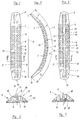
- FIG 1
- eine Draufsicht auf einen ersten Versteifungsstreifen für einen Torwarthandschuh, in einer gerade gerichteten Stellung,
- FIG 2
- eine Seitenansicht des Versteifungsstreifens gemäß Fig. 1, in einer eine Vorbiegung aufweisenden Freistellung, und
- FIG 3
- einen Schnitt gemäß Linie III - III in Fig. 1, in einem gegenüber Fig. 1 vergrößerten Maßstab,
- FIG 4
- eine Draufsicht auf einen zweiten Versteifungsstreifen für einen Torwarthandschuh, in einer gerade gerichteten Stellung, und
- FIG 5
- einen Schnitt gemäß Linie V - V in Fig. 4, in einem gegenüber Fig. 4 vergrößerten Maßstab.
Claims (9)
- Versteifungsstreifen für einen Torwarthandschuh,
bei dem ein biegbares und im wesentlichen zugfestes Trägerband druckfeste Gliederkörper aufgereiht trägt,
bei dem jeweils zwei benachbarte Gliederkörper über eine Drehverbindung miteinander verbunden sind und einander zu dem Trägerband querverlaufende Anschlagflächen zuwenden, die bei einer Streckstellung der beiden benachbarten Gliederkörper gegeneinander gelegt sind,
bei dem die Gliederkörper jeweils mit Höhlung versehen sind und auch der dem Trägerband gegenüberliegenden Seite eine Oberseite bilden,
bei dem das Trägerband mit einer Unterseite jedes Gliederkörpers verklebt ist, und
bei dem jeder Gliederkörper einen Mittenbereich und zwei seitlich anschließende Seitenbereiche bildet, die gegenüber dem Mittenbereich in der Höhe vermindert sind und bei einem Außenrand enden,
dadurch gekennzeichnet, daß bei jedem Gliederkörper (3) die Höhlung (14) zur Oberseite (9) hin offen ist,
wobei die Unterseite (10) jedes Gliederkörpers (3) geschlossen durchgehend flächig ist und die Verklebung (4) des Trägerbandes (1) mit der Unterseite geschlossen flächig durchgehend ist, und
daß die beiden Seitenbereiche (12) von dem Mittenbereich (11) hin zum jeweiligen Außenrand (13) in der Höhe allmählich abnehmen,
wobei auch in den beiden Seitenbereichen (12) zur Oberseite (9) hin offene Höhlung (14) vorgesehen ist. - Versteifungsstreifen nach Anspruch 1, dadurch gekennzeichnet, daß ein in der Höhlung (14) vorgesehener Längssteg (15) zwei Teilhöhlungen (16, 17) voneinander trennt.
- Versteifungsstreifen nach Anspruch 1 oder 2, dadurch gekennzeichnet, daß die Höhlung (14) in jedem Seitenbereich (12) in Richtung zum Außenrand (13) wandungsfrei ist.
- Versteifungsstreifen nach Anspruch 1, 2 oder 3, dadurch gekennzeichnet, daß auf 5 cm Länge des Versteifungsstreifens mehr als 5,2 Gliederkörper (3) vorgesehen sind.
- Versteifungsstreifen nach einem der vorhergehenden Ansprüche und aufweisend zwei Endkörper mit sich zum freien Ende hin verjüngender Breite, dadurch gekennzeichnet, daß sich der Endkörper (2) zusätzlich in der Höhe zum freien Ende (19) hin verjüngt.
- Versteifungsstreifen nach Anspruch 5, dadurch gekennzeichnet, daß sich die Verjüngung der Höhe und/oder der Breite über die gesamte Länge des Endkörpers (2) erstreckt.
- Versteifungsstreifen nach Anspruch 5 oder 6, dadurch gekennzeichnet, daß der Endkörper (2) mindestens doppelt so lang wie der benachbarte Gliederkörper (3) ist.
- Versteifungsstreifen, insbesondere nach einem der vorhergehenden Ansprüche und aufweisend bei einer Freistellung über die Länge hin eine Vorbiegung, bei der ein Verhältnis Bogenlänge : Sekantenlänge gegeben ist, dadurch gekennzeichnet, daß die Vorbiegung verstärkt ist, indem das Verhältnis Bogenlänge (5) : Sekantenlänge (6) > 1,1 ist, und benachbarte Gliederkörper (3) an den Anschlagflächen (8) nahe dem Trägerband (1) unter Vorspannung gegeneinander gedrückt gehalten sind.
- Versteifungsstreifen nach einem der vorhergehenden Ansprüche, dadurch gekennzeichnet, daß ein sämtliche Gliederkörper (3) querender, in jedem Gliederkörper zwischen der Unterseite (10) und der Höhlung (14) angeordneter Kanal (20) vorgesehen ist, der eine zugfeste Seele (21) aufnimmt, deren beider Enden jeweils an einem Endkörper (2) festgelegt sind.
Applications Claiming Priority (2)
| Application Number | Priority Date | Filing Date | Title |
|---|---|---|---|
| DE20107098U DE20107098U1 (de) | 2001-04-25 | 2001-04-25 | Versteifungsstreifen für einen Torwarthandschuh |
| DE20107098U | 2001-04-25 |
Publications (2)
| Publication Number | Publication Date |
|---|---|
| EP1273323A2 true EP1273323A2 (de) | 2003-01-08 |
| EP1273323A3 EP1273323A3 (de) | 2003-08-13 |
Family
ID=7956167
Family Applications (1)
| Application Number | Title | Priority Date | Filing Date |
|---|---|---|---|
| EP02007958A Withdrawn EP1273323A3 (de) | 2001-04-25 | 2002-04-10 | Versteifungsstreifen für einen Torwarthandschuh |
Country Status (3)
| Country | Link |
|---|---|
| US (1) | US6725466B2 (de) |
| EP (1) | EP1273323A3 (de) |
| DE (1) | DE20107098U1 (de) |
Cited By (2)
| Publication number | Priority date | Publication date | Assignee | Title |
|---|---|---|---|---|
| DE10361434B3 (de) * | 2003-12-23 | 2005-09-15 | Hußenöder, Helmut | Versteifungseinrichtung für einen Handschuh, insbesondere Torwarthandschuh |
| EP1632273A1 (de) | 2004-09-06 | 2006-03-08 | Uhlsport GmbH | Fingerprotektor und damit ausgerüsteter Sporthandschuh |
Families Citing this family (20)
| Publication number | Priority date | Publication date | Assignee | Title |
|---|---|---|---|---|
| DE10350448B4 (de) * | 2003-10-30 | 2006-11-09 | Adidas International Marketing B.V. | Verstärkungselement |
| US7293296B1 (en) * | 2003-10-31 | 2007-11-13 | Jeffrey M. Beraznik | Football glove and method of use |
| DE102004022549B3 (de) * | 2004-05-05 | 2005-12-01 | Peter Hochmuth | Versteifungseinrichtung für einen Handschuh, insbesondere Torwarthandschuh |
| US7275268B2 (en) * | 2004-07-13 | 2007-10-02 | J. Debeer & Son, Inc. | Sports glove with a segmented joint protector |
| US7721348B2 (en) | 2005-03-08 | 2010-05-25 | Adidas International Marketing B.V. | Protective element |
| US8341763B2 (en) | 2005-03-30 | 2013-01-01 | Adidas International Marketing B.V. | Reinforcing element |
| DE102005014470B3 (de) | 2005-03-30 | 2006-09-21 | Adidas International Marketing B.V. | Handschuhverstärkungselement |
| US20070118966A1 (en) * | 2005-11-02 | 2007-05-31 | Beraznik Jeffrey M | Exposed Palm Glove and Method of Use |
| US7954168B2 (en) * | 2007-04-13 | 2011-06-07 | Gx, Inc. | Garment sleeve with knuckle protector and thumb aperture |
| US8156572B2 (en) * | 2007-11-29 | 2012-04-17 | Patrick Gerald Whaley | Weighted exercise clothing |
| US20110302687A1 (en) | 2007-11-29 | 2011-12-15 | Patrick Gerald Whaley | Clothing systems having resistance properties |
| US9241519B2 (en) | 2008-09-19 | 2016-01-26 | Ironclad Performance Wear Corporation | Glove for use in the oil and natural gas extraction industries |
| USD683934S1 (en) | 2008-11-26 | 2013-06-11 | Patrick Gerald Whaley | Shirt |
| DE102011004039B4 (de) | 2011-02-14 | 2013-02-21 | Adidas Ag | Handgelenkschutz für einen Sporthandschuh |
| EP2534968B1 (de) * | 2011-06-16 | 2018-06-13 | Endrik Fleischmann | Handschuh mit einem Innenhandteil und einem Oberhandteil sowie Stützelementen |
| US10905181B2 (en) | 2014-06-19 | 2021-02-02 | Robert Sydney Rabbeth, JR. | Glove preventing hyper-extended or jammed fingers |
| US20210038967A1 (en) * | 2018-03-26 | 2021-02-11 | Vincent Chen | Base Material for Preparing Finger Protection Structure and Finger Protection Structure for a Protection Hand Glove |
| CN208286451U (zh) * | 2018-03-26 | 2018-12-28 | 陈元森 | 边缘具有切角的插条结构 |
| DE102023124236A1 (de) * | 2023-09-08 | 2025-03-13 | Hochmuth GmbH & Co. KG | Versteifungseinrichtung für einen Handschuh, insbesondere Torwarthandschuh, und ein Verfahren zu dessen Herstellung |
| AT527232B1 (de) * | 2023-09-12 | 2024-12-15 | Forschungsgesellschaft Der Fh Kaernten Mbh | Medizinische Hilfsvorrichtung |
Family Cites Families (12)
| Publication number | Priority date | Publication date | Assignee | Title |
|---|---|---|---|---|
| DE1680004U (de) * | 1954-05-04 | 1954-07-22 | Sportartikelfabrik Buck | Fingerhandschuh. |
| KR900002699B1 (ko) * | 1985-02-15 | 1990-04-23 | 야마모도 고오가꾸 가부시끼가이샤 | 프로텍터가 부착된 장갑 |
| DE3516545C2 (de) * | 1985-05-08 | 1994-02-17 | Endrik Fleischmann | Handschuh, insbesondere Torwarthandschuh |
| US5274846A (en) * | 1990-06-12 | 1994-01-04 | Hpi Health Protection, Inc. | Cushion having multilayer closed cell structure |
| DE4133178A1 (de) * | 1991-10-07 | 1993-04-08 | O & P Melchinger | Schutzhandschuh fuer polizisten und andere sicherheitskraefte |
| US5946720A (en) * | 1997-04-30 | 1999-09-07 | Bauer, Inc. | Protective glove with ergonomics features |
| AT408502B (de) * | 1998-08-11 | 2001-12-27 | Astron Elastomerprodukte Ges M | Einrichtung zum schutz von gegenständen oder körperteilen vor vibrationen |
| DE19910799C1 (de) * | 1999-03-11 | 2000-08-31 | Reusch International Gmbh & Co | Sporthandschuh, insbesondere Torwarthandschuh |
| HUP9902125A2 (hu) * | 1999-06-23 | 2001-09-28 | László Szabó | Ujjvédő kesztyűbetét, különösen sportkesztyűkhöz |
| FR2797214B1 (fr) * | 1999-08-03 | 2002-11-29 | Salomon Sa | Structure souple - rigide |
| DE20113431U1 (de) * | 2000-10-05 | 2002-02-21 | Hochmuth, Peter, 91757 Treuchtlingen | Handschuh mit Versteifungsstreifen |
| ITRM20010156A1 (it) * | 2001-03-23 | 2002-09-23 | Dainese Spa | Procedimento per la realizzazione di capi di abbigliamento provvisti di elementi di protezione. |
-
2001
- 2001-04-25 DE DE20107098U patent/DE20107098U1/de not_active Expired - Lifetime
-
2002
- 2002-04-10 EP EP02007958A patent/EP1273323A3/de not_active Withdrawn
- 2002-04-24 US US10/132,629 patent/US6725466B2/en not_active Expired - Fee Related
Cited By (3)
| Publication number | Priority date | Publication date | Assignee | Title |
|---|---|---|---|---|
| DE10361434B3 (de) * | 2003-12-23 | 2005-09-15 | Hußenöder, Helmut | Versteifungseinrichtung für einen Handschuh, insbesondere Torwarthandschuh |
| EP1632273A1 (de) | 2004-09-06 | 2006-03-08 | Uhlsport GmbH | Fingerprotektor und damit ausgerüsteter Sporthandschuh |
| US7797758B2 (en) | 2004-09-06 | 2010-09-21 | Uhlsport Gmbh | Finger protector and sports glove equipped therewith |
Also Published As
| Publication number | Publication date |
|---|---|
| US6725466B2 (en) | 2004-04-27 |
| EP1273323A3 (de) | 2003-08-13 |
| US20020184696A1 (en) | 2002-12-12 |
| DE20107098U1 (de) | 2002-10-02 |
Similar Documents
| Publication | Publication Date | Title |
|---|---|---|
| EP1273323A2 (de) | Versteifungsstreifen für einen Torwarthandschuh | |
| EP1203602B1 (de) | Handschuh mit Versteifungsstreifen | |
| DE3036491C2 (de) | Schuhsohle | |
| DE3803507C2 (de) | ||
| DE2003478A1 (de) | Sohle und Absatz aus Gummi oder Kunststoff | |
| DE2623382A1 (de) | Ski und verfahren zu seiner herstellung | |
| DE3840553A1 (de) | Ski mit einem daempfungselement | |
| DE69404090T2 (de) | Alpinski mit verbessertem Profil | |
| DE19520927A1 (de) | Stabband für Stabbandförderer | |
| EP0172159A1 (de) | Skischuh | |
| CH658602A5 (de) | Mehrschichtenski in sandwichbauweise. | |
| DE112007000387T5 (de) | Snowboard und Skier | |
| DE3151585C2 (de) | ||
| DE2704858A1 (de) | Ski, insbesondere zur verwendung fuer tiefschneeabfahrten | |
| AT500213B1 (de) | Schi | |
| DE4318836A1 (de) | Verbindungselement für Förderbänder | |
| WO1981000698A1 (fr) | Luge ou analogue en particulier pour la neige et la glace | |
| DE3116365A1 (de) | Foerderkette | |
| CH660675A5 (de) | Hornhautraspel. | |
| DE3225031C2 (de) | Vorrichtung zum verbinden zweier einander zugekehrten faltenbalgenden miteinander | |
| DE29719608U1 (de) | Schuh mit in der Sohle geführten Spikes | |
| DD238192A5 (de) | Seitliche fuehrungsvorrichtung eines skischuhes, der an seinem vorderen ende auf einem langlaufski befestigt ist | |
| DE2558621C3 (de) | Skipaar | |
| DE19704959A1 (de) | Vorrichtung zum Montieren einer Skibindung | |
| AT391091B (de) | Bindung fuer einen langlaufski |
Legal Events
| Date | Code | Title | Description |
|---|---|---|---|
| PUAI | Public reference made under article 153(3) epc to a published international application that has entered the european phase |
Free format text: ORIGINAL CODE: 0009012 |
|
| AK | Designated contracting states |
Kind code of ref document: A2 Designated state(s): AT BE CH CY DE DK ES FI FR GB GR IE IT LI LU MC NL PT SE TR |
|
| AX | Request for extension of the european patent |
Free format text: AL;LT;LV;MK;RO;SI |
|
| PUAL | Search report despatched |
Free format text: ORIGINAL CODE: 0009013 |
|
| AK | Designated contracting states |
Designated state(s): AT BE CH CY DE DK ES FI FR GB GR IE IT LI LU MC NL PT SE TR |
|
| AX | Request for extension of the european patent |
Extension state: AL LT LV MK RO SI |
|
| RIC1 | Information provided on ipc code assigned before grant |
Ipc: 7A 41D 19/015 B Ipc: 7A 63B 71/14 A |
|
| 17P | Request for examination filed |
Effective date: 20031023 |
|
| AKX | Designation fees paid |
Designated state(s): AT BE CH CY DE DK ES FI FR GB GR IE IT LI LU MC NL PT SE TR |
|
| 17Q | First examination report despatched |
Effective date: 20050510 |
|
| GRAP | Despatch of communication of intention to grant a patent |
Free format text: ORIGINAL CODE: EPIDOSNIGR1 |
|
| STAA | Information on the status of an ep patent application or granted ep patent |
Free format text: STATUS: THE APPLICATION IS DEEMED TO BE WITHDRAWN |
|
| 18D | Application deemed to be withdrawn |
Effective date: 20060404 |