EP1271685A2 - Méthode de controle pour charger et décharger une batterie - Google Patents
Méthode de controle pour charger et décharger une batterie Download PDFInfo
- Publication number
- EP1271685A2 EP1271685A2 EP02013492A EP02013492A EP1271685A2 EP 1271685 A2 EP1271685 A2 EP 1271685A2 EP 02013492 A EP02013492 A EP 02013492A EP 02013492 A EP02013492 A EP 02013492A EP 1271685 A2 EP1271685 A2 EP 1271685A2
- Authority
- EP
- European Patent Office
- Prior art keywords
- battery
- charging
- soc
- discharging
- range
- Prior art date
- Legal status (The legal status is an assumption and is not a legal conclusion. Google has not performed a legal analysis and makes no representation as to the accuracy of the status listed.)
- Granted
Links
Images

Classifications
-
- B—PERFORMING OPERATIONS; TRANSPORTING
- B60—VEHICLES IN GENERAL
- B60L—PROPULSION OF ELECTRICALLY-PROPELLED VEHICLES; SUPPLYING ELECTRIC POWER FOR AUXILIARY EQUIPMENT OF ELECTRICALLY-PROPELLED VEHICLES; ELECTRODYNAMIC BRAKE SYSTEMS FOR VEHICLES IN GENERAL; MAGNETIC SUSPENSION OR LEVITATION FOR VEHICLES; MONITORING OPERATING VARIABLES OF ELECTRICALLY-PROPELLED VEHICLES; ELECTRIC SAFETY DEVICES FOR ELECTRICALLY-PROPELLED VEHICLES
- B60L15/00—Methods, circuits, or devices for controlling the traction-motor speed of electrically-propelled vehicles
- B60L15/20—Methods, circuits, or devices for controlling the traction-motor speed of electrically-propelled vehicles for control of the vehicle or its driving motor to achieve a desired performance, e.g. speed, torque, programmed variation of speed
- B60L15/2045—Methods, circuits, or devices for controlling the traction-motor speed of electrically-propelled vehicles for control of the vehicle or its driving motor to achieve a desired performance, e.g. speed, torque, programmed variation of speed for optimising the use of energy
-
- H—ELECTRICITY
- H02—GENERATION; CONVERSION OR DISTRIBUTION OF ELECTRIC POWER
- H02J—CIRCUIT ARRANGEMENTS OR SYSTEMS FOR SUPPLYING OR DISTRIBUTING ELECTRIC POWER; SYSTEMS FOR STORING ELECTRIC ENERGY
- H02J7/00—Circuit arrangements for charging or depolarising batteries or for supplying loads from batteries
- H02J7/02—Circuit arrangements for charging or depolarising batteries or for supplying loads from batteries for charging batteries from ac mains by converters
- H02J7/04—Regulation of charging current or voltage
-
- B—PERFORMING OPERATIONS; TRANSPORTING
- B60—VEHICLES IN GENERAL
- B60L—PROPULSION OF ELECTRICALLY-PROPELLED VEHICLES; SUPPLYING ELECTRIC POWER FOR AUXILIARY EQUIPMENT OF ELECTRICALLY-PROPELLED VEHICLES; ELECTRODYNAMIC BRAKE SYSTEMS FOR VEHICLES IN GENERAL; MAGNETIC SUSPENSION OR LEVITATION FOR VEHICLES; MONITORING OPERATING VARIABLES OF ELECTRICALLY-PROPELLED VEHICLES; ELECTRIC SAFETY DEVICES FOR ELECTRICALLY-PROPELLED VEHICLES
- B60L53/00—Methods of charging batteries, specially adapted for electric vehicles; Charging stations or on-board charging equipment therefor; Exchange of energy storage elements in electric vehicles
- B60L53/10—Methods of charging batteries, specially adapted for electric vehicles; Charging stations or on-board charging equipment therefor; Exchange of energy storage elements in electric vehicles characterised by the energy transfer between the charging station and the vehicle
- B60L53/11—DC charging controlled by the charging station, e.g. mode 4
-
- B—PERFORMING OPERATIONS; TRANSPORTING
- B60—VEHICLES IN GENERAL
- B60L—PROPULSION OF ELECTRICALLY-PROPELLED VEHICLES; SUPPLYING ELECTRIC POWER FOR AUXILIARY EQUIPMENT OF ELECTRICALLY-PROPELLED VEHICLES; ELECTRODYNAMIC BRAKE SYSTEMS FOR VEHICLES IN GENERAL; MAGNETIC SUSPENSION OR LEVITATION FOR VEHICLES; MONITORING OPERATING VARIABLES OF ELECTRICALLY-PROPELLED VEHICLES; ELECTRIC SAFETY DEVICES FOR ELECTRICALLY-PROPELLED VEHICLES
- B60L58/00—Methods or circuit arrangements for monitoring or controlling batteries or fuel cells, specially adapted for electric vehicles
- B60L58/10—Methods or circuit arrangements for monitoring or controlling batteries or fuel cells, specially adapted for electric vehicles for monitoring or controlling batteries
-
- H—ELECTRICITY
- H01—ELECTRIC ELEMENTS
- H01M—PROCESSES OR MEANS, e.g. BATTERIES, FOR THE DIRECT CONVERSION OF CHEMICAL ENERGY INTO ELECTRICAL ENERGY
- H01M10/00—Secondary cells; Manufacture thereof
- H01M10/42—Methods or arrangements for servicing or maintenance of secondary cells or secondary half-cells
- H01M10/44—Methods for charging or discharging
-
- H—ELECTRICITY
- H02—GENERATION; CONVERSION OR DISTRIBUTION OF ELECTRIC POWER
- H02J—CIRCUIT ARRANGEMENTS OR SYSTEMS FOR SUPPLYING OR DISTRIBUTING ELECTRIC POWER; SYSTEMS FOR STORING ELECTRIC ENERGY
- H02J7/00—Circuit arrangements for charging or depolarising batteries or for supplying loads from batteries
- H02J7/007—Regulation of charging or discharging current or voltage
- H02J7/0071—Regulation of charging or discharging current or voltage with a programmable schedule
-
- H—ELECTRICITY
- H02—GENERATION; CONVERSION OR DISTRIBUTION OF ELECTRIC POWER
- H02J—CIRCUIT ARRANGEMENTS OR SYSTEMS FOR SUPPLYING OR DISTRIBUTING ELECTRIC POWER; SYSTEMS FOR STORING ELECTRIC ENERGY
- H02J7/00—Circuit arrangements for charging or depolarising batteries or for supplying loads from batteries
- H02J7/007—Regulation of charging or discharging current or voltage
- H02J7/00712—Regulation of charging or discharging current or voltage the cycle being controlled or terminated in response to electric parameters
- H02J7/007182—Regulation of charging or discharging current or voltage the cycle being controlled or terminated in response to electric parameters in response to battery voltage
-
- Y—GENERAL TAGGING OF NEW TECHNOLOGICAL DEVELOPMENTS; GENERAL TAGGING OF CROSS-SECTIONAL TECHNOLOGIES SPANNING OVER SEVERAL SECTIONS OF THE IPC; TECHNICAL SUBJECTS COVERED BY FORMER USPC CROSS-REFERENCE ART COLLECTIONS [XRACs] AND DIGESTS
- Y02—TECHNOLOGIES OR APPLICATIONS FOR MITIGATION OR ADAPTATION AGAINST CLIMATE CHANGE
- Y02E—REDUCTION OF GREENHOUSE GAS [GHG] EMISSIONS, RELATED TO ENERGY GENERATION, TRANSMISSION OR DISTRIBUTION
- Y02E60/00—Enabling technologies; Technologies with a potential or indirect contribution to GHG emissions mitigation
- Y02E60/10—Energy storage using batteries
-
- Y—GENERAL TAGGING OF NEW TECHNOLOGICAL DEVELOPMENTS; GENERAL TAGGING OF CROSS-SECTIONAL TECHNOLOGIES SPANNING OVER SEVERAL SECTIONS OF THE IPC; TECHNICAL SUBJECTS COVERED BY FORMER USPC CROSS-REFERENCE ART COLLECTIONS [XRACs] AND DIGESTS
- Y02—TECHNOLOGIES OR APPLICATIONS FOR MITIGATION OR ADAPTATION AGAINST CLIMATE CHANGE
- Y02T—CLIMATE CHANGE MITIGATION TECHNOLOGIES RELATED TO TRANSPORTATION
- Y02T10/00—Road transport of goods or passengers
- Y02T10/60—Other road transportation technologies with climate change mitigation effect
- Y02T10/64—Electric machine technologies in electromobility
-
- Y—GENERAL TAGGING OF NEW TECHNOLOGICAL DEVELOPMENTS; GENERAL TAGGING OF CROSS-SECTIONAL TECHNOLOGIES SPANNING OVER SEVERAL SECTIONS OF THE IPC; TECHNICAL SUBJECTS COVERED BY FORMER USPC CROSS-REFERENCE ART COLLECTIONS [XRACs] AND DIGESTS
- Y02—TECHNOLOGIES OR APPLICATIONS FOR MITIGATION OR ADAPTATION AGAINST CLIMATE CHANGE
- Y02T—CLIMATE CHANGE MITIGATION TECHNOLOGIES RELATED TO TRANSPORTATION
- Y02T10/00—Road transport of goods or passengers
- Y02T10/60—Other road transportation technologies with climate change mitigation effect
- Y02T10/70—Energy storage systems for electromobility, e.g. batteries
-
- Y—GENERAL TAGGING OF NEW TECHNOLOGICAL DEVELOPMENTS; GENERAL TAGGING OF CROSS-SECTIONAL TECHNOLOGIES SPANNING OVER SEVERAL SECTIONS OF THE IPC; TECHNICAL SUBJECTS COVERED BY FORMER USPC CROSS-REFERENCE ART COLLECTIONS [XRACs] AND DIGESTS
- Y02—TECHNOLOGIES OR APPLICATIONS FOR MITIGATION OR ADAPTATION AGAINST CLIMATE CHANGE
- Y02T—CLIMATE CHANGE MITIGATION TECHNOLOGIES RELATED TO TRANSPORTATION
- Y02T10/00—Road transport of goods or passengers
- Y02T10/60—Other road transportation technologies with climate change mitigation effect
- Y02T10/7072—Electromobility specific charging systems or methods for batteries, ultracapacitors, supercapacitors or double-layer capacitors
-
- Y—GENERAL TAGGING OF NEW TECHNOLOGICAL DEVELOPMENTS; GENERAL TAGGING OF CROSS-SECTIONAL TECHNOLOGIES SPANNING OVER SEVERAL SECTIONS OF THE IPC; TECHNICAL SUBJECTS COVERED BY FORMER USPC CROSS-REFERENCE ART COLLECTIONS [XRACs] AND DIGESTS
- Y02—TECHNOLOGIES OR APPLICATIONS FOR MITIGATION OR ADAPTATION AGAINST CLIMATE CHANGE
- Y02T—CLIMATE CHANGE MITIGATION TECHNOLOGIES RELATED TO TRANSPORTATION
- Y02T10/00—Road transport of goods or passengers
- Y02T10/60—Other road transportation technologies with climate change mitigation effect
- Y02T10/72—Electric energy management in electromobility
-
- Y—GENERAL TAGGING OF NEW TECHNOLOGICAL DEVELOPMENTS; GENERAL TAGGING OF CROSS-SECTIONAL TECHNOLOGIES SPANNING OVER SEVERAL SECTIONS OF THE IPC; TECHNICAL SUBJECTS COVERED BY FORMER USPC CROSS-REFERENCE ART COLLECTIONS [XRACs] AND DIGESTS
- Y02—TECHNOLOGIES OR APPLICATIONS FOR MITIGATION OR ADAPTATION AGAINST CLIMATE CHANGE
- Y02T—CLIMATE CHANGE MITIGATION TECHNOLOGIES RELATED TO TRANSPORTATION
- Y02T90/00—Enabling technologies or technologies with a potential or indirect contribution to GHG emissions mitigation
- Y02T90/10—Technologies relating to charging of electric vehicles
- Y02T90/12—Electric charging stations
-
- Y—GENERAL TAGGING OF NEW TECHNOLOGICAL DEVELOPMENTS; GENERAL TAGGING OF CROSS-SECTIONAL TECHNOLOGIES SPANNING OVER SEVERAL SECTIONS OF THE IPC; TECHNICAL SUBJECTS COVERED BY FORMER USPC CROSS-REFERENCE ART COLLECTIONS [XRACs] AND DIGESTS
- Y02—TECHNOLOGIES OR APPLICATIONS FOR MITIGATION OR ADAPTATION AGAINST CLIMATE CHANGE
- Y02T—CLIMATE CHANGE MITIGATION TECHNOLOGIES RELATED TO TRANSPORTATION
- Y02T90/00—Enabling technologies or technologies with a potential or indirect contribution to GHG emissions mitigation
- Y02T90/10—Technologies relating to charging of electric vehicles
- Y02T90/14—Plug-in electric vehicles
Definitions
- the present invention relates to a method for controlling charging and discharging processes with respect to a battery mounted on an electric vehicle, an electric powered carrier vehicle, or the like.
- An automated guided vehicle is an electrically driven vehicle which uses a battery as at least a part of a power source thereof.
- AGVs are used as electric powered carrier vehicles for automatically carrying parts at assembly plants for a variety of products.
- Abattery mounted on an AGV is, for example, a high-voltage battery pack including a plurality of rechargeable cells serially connected together.
- An AGV typically travels in a plant from a station as a starting point along a predetermined path and returns to the station so as to charge the battery mounted thereon. This operation is repeatedly performed. Electric power consumed by traveling along the predetermined path is usually as slight as substantially 10% of the battery capacity.
- the battery is not intended to be fully charged for safety reasons, etc., and therefore the battery is repeatedly charged and discharged such that the battery SOC (state of charge) is in a range from about 50% to about 60%, for example.
- the charging memory effect refers to a phenomenon such as an increase in voltage caused at the last stage of a charging process by repeatedly charging and discharging a battery in a shallow SOC range.
- the charging memory effect is caused in a specific SOC range, when an SOC value of the battery is increased so as to be higher than a value in the specific SOC range, a battery voltage is increased, thereby causing a reduction in charging efficiency, for example.
- the battery voltage has a tendency to increase according to an increase in the SOC value. Both in the range of a low SOC value which is in the proximity of 0% and the range of a high SOC value which is in the proximity of 100%, the battery voltage is significantly increased. The battery voltage has a slight tendency to increase between both ranges according to an increase in the SOC value.
- the aforementioned AGV employs a system in which, when an excessive charging voltage is detected, a battery of the AGV is forcedly discharged for safety so as to cause the SOC value to be decreased to a lowest level in a range of the SOC values in which the charging and discharging processes are performed.
- the range of the SOC values in which the charging and discharging processes are performed is between about 50% and about 60% and a battery voltage corresponding to about 70% of the SOC is set so as to be a highest voltage for charging the battery
- the charging and discharging processes are usually performed such that the battery voltage corresponds to between about 50% of the SOC and about 60% of the SOC.
- the battery is forcedly discharged so as to have the SOC value of 50% which is the lowest level in the range of the SOC values in which the charging and discharging processes are performed.
- the battery voltage is rapidly increased, and therefore the battery voltage is erroneously detected as if the value of the battery voltage is at the highest level for charging the battery, so that the battery is forcedly discharged although the level of the battery voltage is lower than the highest level.
- the SOC value is decreased to the lowest level in the range of the SOC values in which the charging and discharging processes are performed. In this manner, the SOC value of the battery is forcedly decreased so as not to sufficiently charge the battery, and therefore repeating this operation might cause the battery of the AGV to be incapable of being sufficiently charged.
- the battery voltage corresponding to about 70% of the SOC is set so as to be the highest voltage for charging the battery
- the charging memory effect causes the battery voltage to be considered by a detector (not shown) as being increased to the highest voltage while the actual battery voltage corresponds to about 60% of the SOC
- the battery is forcedly discharged so as to have the SOC value of 50%.
- the charging and discharging processes are performed with respect to the battery which is not sufficiently charged.
- the battery of the AGV is forcedly discharged at a low SOC value due to the charging memory effect, the battery is not sufficiently charged, which may cause the AGV to be incapable of traveling.
- the charging memory effect can be prevented by performing a refresh charging and discharging process such that the battery is forcedly discharged so as to have the SOC value of 0% and is fully charged so as to have the SOC value of 100%.
- a refresh charging and discharging process such that the battery is forcedly discharged so as to have the SOC value of 0% and is fully charged so as to have the SOC value of 100%.
- such a process is usually required to be repeated for a period of several cycles.
- Figure 4 is a graph showing relationships between the number of cycles in the refresh charging and discharging process and the charging memory effect.
- a relationship between the SOC value and the battery voltage denoted by (a) refers to a case where one cycle of the refresh charging and discharging process is performed. In this case, the charging memory effect is caused when the SOC value is between about 50% and about 60%.
- Another relationship between the SOC value and the battery voltage denoted by (b) refers to a case where two cycles of the refresh charging and discharging processes are performed. In this case, the charging memory effect is caused when the SOC value is between about 60% and about 80%.
- Still another relationship between the SOC value and the battery voltage denoted by (c) refers to a case where five cycles of the refresh charging and discharging processes are performed. In this case, the charging memory effect is caused when the SOC value is between about 80% and about 100%.
- Still another relationship between the SOC value and the battery voltage denoted by (d) refers to a case where six cycles of the refresh charging and discharging processes are performed. Still another relationship between the SOC value and the battery voltage denoted by (e) refers to cases where seven and eight cycles of the refresh charging and discharging processes are performed. In these cases, the charging memory effect is hardly caused. Therefore, it is necessary to perform the refresh charging and discharging processes six times or more so as to prevent the charging memory effect.
- HEV battery The battery for a HEV (hereinafter, referred to as "HEV battery”) stores not only electric power for driving an electric motor but also electric power generated in a regenerative cycle.
- the HEV battery is charged by a heat engine mounted thereon. Therefore, in order to prevent the HEV battery from being rapidly charged, as in the aforementioned case of the battery of the AGV (hereinafter, referred to as "AGV battery”), the HEV battery is charged and discharged so as to have a prescribed SOC value. Accordingly, there is also a possibility that the charging efficiency of the HEV battery can be reduced when the charging memory effect is caused.
- a method for controlling battery charging and discharging in which a battery is charged and discharged such that a SOC (state of charge) value of the battery is increased/decreased to a predetermined range when the SOC value of the battery is in a predetermined range; and a range of the SOC values in which charging and discharging processes are performed sequentially varies and a range of the SOC values after the charging and discharging processes also sequentially varies.
- both the range of the SOC values in which charging and discharging processes are performed and the range of the SOC values after the charging and discharging processes vary between 10% and 100%.
- both the range of the SOC values in which charging and discharging processes are performed and the range of the SOC values after the charging and discharging processes vary in stages from a low SOC value to a high SOC value.
- charging and discharging processes are performed such that the SOC value is decreased in stages when the range of the SOC values after the charging and discharging processes is between 40% and 100%.
- the invention described herein makes possible the advantages of providing a method for controlling battery charging and discharging which can prevent charging efficiency of a battery from being reduced due to a charging memory effect.
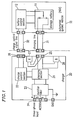
- FIG. 1 is a block diagram showing an automated guided vehicle (AGV) 10 using a method for controlling battery charging and discharging according to the present invention and a charger for the AGV 10 .
- AGV automated guided vehicle
- the AGV 10 is intended to travel along a prescribed path in a plant, a warehouse, or the like.
- the AGV 10 includes a battery 11 as a power source and a battery control section 12 for controlling, for example, a discharging process with respect to the battery 11 .
- the battery 11 is a battery pack including a plurality of cells serially connected together.
- the cell used in the battery 11 is a sealed nickel-metal hydride battery.
- the battery control section 12 stores input information with respect to the battery 11 , such as SOC values, temperatures and the like.
- the AGV 10 travels in a plant from a station as a starting point along a predetermined path and returns to the station so as to charge the battery 11 by means of the charger 20 provided at the station.
- the battery 11 is connected to a charging line 31 which is connected to the charger 20 provided at the station when the battery 11 is being charged by the charger 20 .
- the battery control section 12 is connected to a charge control signal line 32 through which information is input/output from/to the charger 20 when the battery 11 is being charged by the charger 20 .
- the charger 20 includes a charging section 21 for charging the battery 11 and a charge control section 22 for controlling the charging section 21 .
- the charging section 21 is connected to a rectifier filter 23 and receives three-phase alternating current (AC 200 V) input from an input terminal 24 through the rectifier filter 23 .
- the charging section 21 includes a charge terminal 25 connected to the charging line 31 when charging the battery 11 .
- the charge control section 22 includes a control signal terminal 26 which is connected to the charge control signal line 32 when charging the battery 11 .
- the charge terminal 25 is connected to a voltmeter 27 for detecting a voltage applied to the battery 11 when charging the battery 11 .
- An amperemeter 28 is connected between the charging section 21 and the charge terminal 25 for detecting current applied to the battery 11 when charging the battery 11 .
- the battery 11 mounted on the AGV 10 structured in the above-described manner is charged by the charger 20 provided at the station in the following manner.
- the battery 11 mounted on the AGV 10 usually consumes (discharges) a substantially fixed quantity of electric power during each journey along the prescribed path.
- the charging line 31 and charge control signal line 32 of the AGV 10 are respectively connected to the charge terminal 25 and control signal terminal 26 of the charger 20 .
- the charging section 21 receives three-phase alternating current which is input from the input terminal 24 and rectified by the rectifier filter 23 .
- the charging section 21 is controlled by the charge control section 22 so as to apply the received current to the battery 11 via the charging line 31 .
- the charge control section 22 controls the charging section 21 based on a signal output by the battery control section 12 via the charge control signal line 32 .
- the battery 11 is intended to receive a greater quantity of charge power than a quantity of power discharged for each journey along the prescribed path, thereby increasing the SOC value of the battery 11 by a substantially fixed quantity.
- the quantity of power discharged from the battery 11 for each journey of the AGV 10 corresponds to 10% of the SOC
- the quantity of charge power applied to the battery 11 corresponds to 20% of the SOC. Accordingly, the SOC value of the battery 11 is increased by 10% through the charging process performed by the charger 20 for each journey of the AGV 10 .
- the SOC value of the battery 11 is increased each time the battery 11 is charged by the charger 20 .
- the charge control section 22 controls the charging section 21 such that the quantity of charge applied to the battery 11 is zero, and therefore the charging operation performed by the charger 20 on the battery 11 is ceased. Accordingly, the battery 11 is discharged through the journeys of the AGV 10 and the SOC value of the battery 11 is sequentially reduced until the SOC value becomes 10%.
- the quantity of charge power applied to the battery 11 is set so as to correspond to 10% of the SOC and the quantity of power discharged from the battery 11 is set so as to correspond to 20% of the SOC.
- the SOC value of the battery 11 is forcedly reduced by 10%, for example, such that the SOC value becomes 10%.
- the quantity of charge power applied to the battery 11 by the charger 20 corresponds to 20% of the SOC, thereby charging the battery 11 .
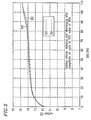
- Figure 2 is a graph showing relationships between the SOC value and the battery voltage with respect to the AGV 10 using the method of charging and discharging according to the present invention.
- a relationship between the SOC value and the battery voltage denoted by (a) refers to a case where one cycle of the refresh charging and discharging process is performed by controlling charging and discharging of the battery 11 so as to sequentially change the SOC value in a range of between about 10% and about 100%, forcedly discharging remaining power from the battery 11 when the SOC value is increased to about 90%, and fully charging the battery 11 .
- Another relationship between the SOC value and the battery voltage denoted by (b) refers to a case where two cycles of the refresh charging and discharging processes are performed in the same manner as in the case of (a).
- One or two cycles of the refresh charging and discharging processes provide significant refresh effects so as to prevent the occurrence of the charging memory effect.
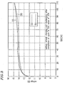
- Figure 3 is a graph showing relationships between the SOC value and the battery voltage with respect to the AGV 10 using the method of charging and discharging according to the present invention.
- a relationship between the SOC value and the battery voltage denoted by (a) refers to a case where one cycle of the refresh charging and discharging process is performed by controlling charging and discharging of the battery 11 so as to sequentially change the SOC value in a range of between about 10% and about 100%, forcedly discharging remaining power from the battery 11 when the SOC value is decreased to about 10%, and fully charging the battery 11 .
- Another relationship between the SOC value and the battery voltage denoted by (b) refers to a case where two cycles of the refresh charging and discharging processes are performed in the same manner as in the case of (a).
- One or two cycles of the refresh charging and discharging processes provide significant refresh effects so as to prevent the occurrence of the charging memory effect.
- both the range of the SOC values at which the charging and discharging processes are performed and the range of the SOC values of charge power applied to the battery 11 are preferably between 10% and 100%, and more preferably between 20% and 80%.
- the present invention is not limited to the above-described configuration in which the battery 11 is excessively charged until the SOC value of the battery 11 is increased to a predetermined highest level, and charging and discharging processes are performed so as to apply zero charge power to the battery 11 or excessively discharge greater power from the battery 11 than charge power applied thereto until the SOC value is decreased to the predetermined lowest level.
- the present invention can be configured such the battery 11 is excessively charged until a prescribed parameter, such as a highest voltage, a highest temperature, an increase in temperature per unit time (dT/dt), or current-voltage (I-V) of the battery 11 , reaches its highest level, and then is excessively discharged such that power discharged from the battery 11 is greater than charge power applied thereto until the prescribed parameter reaches its lowest level.
- a prescribed parameter such as a highest voltage, a highest temperature, an increase in temperature per unit time (dT/dt), or current-voltage (I-V) of the battery 11 .
- necessary information with respect to the battery 11 is suitably provided to the charge control section 22 via the battery control section 12.
- the present invention is not limited to such a case and is applicable to a HEV battery which is charged and discharged in a prescribed SOC range in which the SOC value is less than 100%.
- both the range of the SOC values at which the charging and discharging processes are performed and the range of the SOC values after the charging and discharging processes are sequentially changed, and therefore there is substantially no possibility that the charging memory effect is caused in the battery. Accordingly, it is possible to prevent erroneous detection of the highest charging voltage due to a charge voltage increased when the charging memory effect occurs. Further, it is possible to reduce the number of cycles of a refresh charging and discharging process required for preventing the charging memory effect.
Applications Claiming Priority (2)
| Application Number | Priority Date | Filing Date | Title |
|---|---|---|---|
| JP2001187143A JP3934365B2 (ja) | 2001-06-20 | 2001-06-20 | バッテリの充放電制御方法 |
| JP2001187143 | 2001-06-20 |
Publications (3)
| Publication Number | Publication Date |
|---|---|
| EP1271685A2 true EP1271685A2 (fr) | 2003-01-02 |
| EP1271685A3 EP1271685A3 (fr) | 2007-07-04 |
| EP1271685B1 EP1271685B1 (fr) | 2010-03-17 |
Family
ID=19026479
Family Applications (1)
| Application Number | Title | Priority Date | Filing Date |
|---|---|---|---|
| EP02013492A Expired - Lifetime EP1271685B1 (fr) | 2001-06-20 | 2002-06-17 | Méthode de controle pour charger et décharger une batterie |
Country Status (7)
| Country | Link |
|---|---|
| US (1) | US6661201B2 (fr) |
| EP (1) | EP1271685B1 (fr) |
| JP (1) | JP3934365B2 (fr) |
| KR (1) | KR100472802B1 (fr) |
| CN (1) | CN1235310C (fr) |
| DE (1) | DE60235676D1 (fr) |
| TW (1) | TW548863B (fr) |
Cited By (2)
| Publication number | Priority date | Publication date | Assignee | Title |
|---|---|---|---|---|
| EP2557654A3 (fr) * | 2011-06-28 | 2014-12-10 | Kabushiki Kaisha Toshiba | Appareil de stockage d'énergie et système de stockage d'énergie |
| EP2822201A4 (fr) * | 2012-02-28 | 2016-04-27 | Sumitomo Electric Industries | Système de communication, dispositif de communication, dispositif d'alimentation électrique et véhicule |
Families Citing this family (40)
| Publication number | Priority date | Publication date | Assignee | Title |
|---|---|---|---|---|
| DE10256545A1 (de) * | 2002-12-04 | 2004-06-24 | Hilti Ag | Ladeverfahren für Akkumulatorenpacks |
| WO2004104781A2 (fr) * | 2003-05-19 | 2004-12-02 | J Maev Jack Ivan | Procede et appareil pour recevoir un avertissement concernant un produit pour un composant subordonne |
| JP2005006461A (ja) * | 2003-06-13 | 2005-01-06 | Panasonic Ev Energy Co Ltd | 無人搬送車用二次電池の充放電制御方法 |
| US7321220B2 (en) * | 2003-11-20 | 2008-01-22 | Lg Chem, Ltd. | Method for calculating power capability of battery packs using advanced cell model predictive techniques |
| US7301304B2 (en) * | 2004-02-14 | 2007-11-27 | General Motors Corporation | Energy storage system state of charge diagnostic |
| US8103485B2 (en) | 2004-11-11 | 2012-01-24 | Lg Chem, Ltd. | State and parameter estimation for an electrochemical cell |
| WO2006057469A1 (fr) * | 2004-11-29 | 2006-06-01 | Lg Chem, Ltd. | Procede et systeme d'estimation de l'etat et des parametres d'une batterie |
| WO2006057468A1 (fr) * | 2004-11-29 | 2006-06-01 | Lg Chem, Ltd. | Procede et systeme d'estimation de parametres et d'etats d'une batterie |
| KR100916510B1 (ko) | 2004-11-29 | 2009-09-08 | 주식회사 엘지화학 | 조인트 배터리 상태와 파라미터 추정 시스템 및 방법 |
| KR100863888B1 (ko) * | 2005-03-04 | 2008-10-15 | 주식회사 엘지화학 | 하이브리드 전기 자동차용 배터리의 최대 출력 추정 방법 |
| US7723957B2 (en) * | 2005-11-30 | 2010-05-25 | Lg Chem, Ltd. | System, method, and article of manufacture for determining an estimated battery parameter vector |
| KR100878123B1 (ko) * | 2007-05-14 | 2009-01-12 | 주식회사 엘지화학 | 배터리 상태 및 파라미터 추정 시스템 및 방법 |
| JP5036416B2 (ja) * | 2007-06-15 | 2012-09-26 | トヨタ自動車株式会社 | 電源システムおよびそれを備えた車両、ならびに充放電制御方法 |
| US7994755B2 (en) | 2008-01-30 | 2011-08-09 | Lg Chem, Ltd. | System, method, and article of manufacture for determining an estimated battery cell module state |
| JP5018681B2 (ja) | 2008-08-01 | 2012-09-05 | トヨタ自動車株式会社 | リチウムイオン二次電池の制御方法、及び、リチウムイオン二次電池システム |
| US7890228B2 (en) * | 2008-12-01 | 2011-02-15 | Savant Automation, Inc. | Power source monitoring system for AGVs and method |
| JP5243971B2 (ja) * | 2009-01-05 | 2013-07-24 | 株式会社アルファ | ケーブルの配線構造 |
| US8629657B2 (en) * | 2009-12-31 | 2014-01-14 | Tesla Motors, Inc. | State of charge range |
| US8341449B2 (en) | 2010-04-16 | 2012-12-25 | Lg Chem, Ltd. | Battery management system and method for transferring data within the battery management system |
| JP5732766B2 (ja) * | 2010-07-23 | 2015-06-10 | トヨタ自動車株式会社 | 車両の制御装置および制御方法 |
| CN102570792B (zh) * | 2010-12-23 | 2015-07-15 | 上海汽车集团股份有限公司 | 直流高低压转换器的电压设定点的控制方法 |
| DE102011003518B4 (de) | 2011-02-02 | 2013-01-03 | Siemens Aktiengesellschaft | Verfahren zum Schutz eines Ladekabels und Ladeeinrichtung |
| US8449998B2 (en) | 2011-04-25 | 2013-05-28 | Lg Chem, Ltd. | Battery system and method for increasing an operational life of a battery cell |
| US8471522B2 (en) * | 2011-05-06 | 2013-06-25 | Toyota Motor Engineering & Manufacturing North America, Inc. | System for charging electrically powered automated guided vehicles |
| US8974929B2 (en) | 2011-06-30 | 2015-03-10 | Lg Chem, Ltd. | Heating system for a battery module and method of heating the battery module |
| US8974928B2 (en) | 2011-06-30 | 2015-03-10 | Lg Chem, Ltd. | Heating system for a battery module and method of heating the battery module |
| US8859119B2 (en) | 2011-06-30 | 2014-10-14 | Lg Chem, Ltd. | Heating system for a battery module and method of heating the battery module |
| US8993136B2 (en) | 2011-06-30 | 2015-03-31 | Lg Chem, Ltd. | Heating system for a battery module and method of heating the battery module |
| US9285432B2 (en) * | 2011-07-26 | 2016-03-15 | GM Global Technology Operations LLC | Method and system for controlling a vehicle battery |
| JP5928683B2 (ja) * | 2011-09-08 | 2016-06-01 | スズキ株式会社 | 電気自動車の電力供給制御装置 |
| DE102011087496A1 (de) * | 2011-11-30 | 2013-06-27 | H-Tech Ag | Verfahren und Vorrichtung zum Laden von wiederaufladbaren Zellen |
| CN103158570B (zh) * | 2011-12-16 | 2016-07-13 | 北汽福田汽车股份有限公司 | 纯电动汽车的高压附件能量管理方法 |
| KR101301760B1 (ko) * | 2012-01-31 | 2013-08-29 | 조선대학교산학협력단 | 전기차량의 회생제동 제어장치 |
| US10664562B2 (en) * | 2013-02-24 | 2020-05-26 | Fairchild Semiconductor Corporation and University of Connecticut | Battery state of charge tracking, equivalent circuit selection and benchmarking |
| CN105196887B (zh) * | 2015-10-13 | 2019-02-22 | 北京新能源汽车股份有限公司 | 电动汽车的充电控制方法和充电控制系统 |
| WO2017141284A1 (fr) * | 2016-02-15 | 2017-08-24 | 株式会社 ゴーダ水処理技研 | Dispositif de génération d'eau électrolysée |
| JP6455497B2 (ja) * | 2016-11-16 | 2019-01-23 | トヨタ自動車株式会社 | 車両の電池システム及びその制御方法 |
| FR3087057B1 (fr) * | 2018-10-09 | 2022-11-11 | Renault Sas | Procede et dispositif de regulation du niveau de charge d'une batterie de traction d'un vehicule electrique |
| US11661029B2 (en) * | 2020-06-24 | 2023-05-30 | TWS Technology(Guangzhou) Limited | Authentication between battery management system (BMS) and battery host platform |
| CN113581008B (zh) * | 2021-09-28 | 2021-12-28 | 深圳万甲荣实业有限公司 | 一种新能源汽车用阶段式功率调配的电源系统 |
Citations (3)
| Publication number | Priority date | Publication date | Assignee | Title |
|---|---|---|---|---|
| DE19736414A1 (de) * | 1996-08-22 | 1998-03-05 | Toyota Motor Co Ltd | Elektromotorfahrzeug |
| WO2000031818A1 (fr) * | 1998-11-24 | 2000-06-02 | Matsushita Electric Industrial Co., Ltd. | Procede de commande de charge/decharge d'un accumulateur |
| EP1086848A2 (fr) * | 1999-09-24 | 2001-03-28 | Hitachi, Ltd. | Véhicule hybride |
Family Cites Families (5)
| Publication number | Priority date | Publication date | Assignee | Title |
|---|---|---|---|---|
| US4912416A (en) * | 1988-06-06 | 1990-03-27 | Champlin Keith S | Electronic battery testing device with state-of-charge compensation |
| US4876513A (en) * | 1988-12-05 | 1989-10-24 | Globe-Union Inc. | Dynamic state-of-charge indicator for a battery and method thereof |
| US5998968A (en) * | 1997-01-07 | 1999-12-07 | Ion Control Solutions, Llc | Method and apparatus for rapidly charging and reconditioning a battery |
| JP3545597B2 (ja) | 1998-04-30 | 2004-07-21 | 松下電器産業株式会社 | 二次電池充電装置 |
| JP3716619B2 (ja) * | 1998-05-14 | 2005-11-16 | 日産自動車株式会社 | 電池の残容量計 |
-
2001
- 2001-06-20 JP JP2001187143A patent/JP3934365B2/ja not_active Expired - Fee Related
-
2002
- 2002-06-17 DE DE60235676T patent/DE60235676D1/de not_active Expired - Lifetime
- 2002-06-17 EP EP02013492A patent/EP1271685B1/fr not_active Expired - Lifetime
- 2002-06-18 TW TW091113247A patent/TW548863B/zh not_active IP Right Cessation
- 2002-06-18 US US10/175,437 patent/US6661201B2/en not_active Expired - Fee Related
- 2002-06-20 CN CNB021226970A patent/CN1235310C/zh not_active Expired - Fee Related
- 2002-06-20 KR KR10-2002-0034499A patent/KR100472802B1/ko not_active IP Right Cessation
Patent Citations (3)
| Publication number | Priority date | Publication date | Assignee | Title |
|---|---|---|---|---|
| DE19736414A1 (de) * | 1996-08-22 | 1998-03-05 | Toyota Motor Co Ltd | Elektromotorfahrzeug |
| WO2000031818A1 (fr) * | 1998-11-24 | 2000-06-02 | Matsushita Electric Industrial Co., Ltd. | Procede de commande de charge/decharge d'un accumulateur |
| EP1086848A2 (fr) * | 1999-09-24 | 2001-03-28 | Hitachi, Ltd. | Véhicule hybride |
Cited By (2)
| Publication number | Priority date | Publication date | Assignee | Title |
|---|---|---|---|---|
| EP2557654A3 (fr) * | 2011-06-28 | 2014-12-10 | Kabushiki Kaisha Toshiba | Appareil de stockage d'énergie et système de stockage d'énergie |
| EP2822201A4 (fr) * | 2012-02-28 | 2016-04-27 | Sumitomo Electric Industries | Système de communication, dispositif de communication, dispositif d'alimentation électrique et véhicule |
Also Published As
| Publication number | Publication date |
|---|---|
| JP2003009415A (ja) | 2003-01-10 |
| TW548863B (en) | 2003-08-21 |
| KR20020097022A (ko) | 2002-12-31 |
| DE60235676D1 (de) | 2010-04-29 |
| US20030001541A1 (en) | 2003-01-02 |
| EP1271685B1 (fr) | 2010-03-17 |
| CN1235310C (zh) | 2006-01-04 |
| EP1271685A3 (fr) | 2007-07-04 |
| JP3934365B2 (ja) | 2007-06-20 |
| US6661201B2 (en) | 2003-12-09 |
| CN1392626A (zh) | 2003-01-22 |
| KR100472802B1 (ko) | 2005-03-10 |
Similar Documents
| Publication | Publication Date | Title |
|---|---|---|
| US6661201B2 (en) | Method for controlling battery charge and discharge | |
| EP1249886B1 (fr) | Méthode de contrôle de chargement d'une batterie secondaire pour un véhicule auto-guidé | |
| US5659240A (en) | Intelligent battery charger for electric drive system batteries | |
| US8237398B2 (en) | Electric system, charging device and charging method for electric system for discharging of a power storage mechanism for resetting a state of a charge | |
| CN102104176A (zh) | 电池系统、具备其的车辆以及电池系统的限流状态检测法 | |
| EP0926799B1 (fr) | Dispositif d'alimentation en energie | |
| EP3410558A1 (fr) | Dispositif de commande de batterie | |
| JP2000092732A (ja) | 組電池のばらつき判定方法及びバッテリ装置 | |
| CN105322613A (zh) | 用于锂离子电池的快速充电算法 | |
| CN102064571A (zh) | 电池的可充放电电流运算方法和电源装置以及配备该电源装置的车辆 | |
| JP2001145213A (ja) | バッテリ充電方法 | |
| CN101141070A (zh) | 一种新型智能电机电池控制系统 | |
| CN103154759A (zh) | 蓄电装置的诊断装置、诊断方法以及蓄电装置 | |
| KR20030070812A (ko) | 전기 자동차용 전원 장치 | |
| JP3855497B2 (ja) | 組電池の充放電状態判定方法及び装置 | |
| US6465988B2 (en) | Charging/discharging control device and method for canceling memory effect in secondary battery | |
| CN108602443A (zh) | 控制设备和用于放电可再充电蓄电池的方法 | |
| WO2003003035A1 (fr) | Systeme de mesure de tension exact utilisant des circuits isoles de relais | |
| US6218812B1 (en) | Solid state battery charger | |
| EP1161788A1 (fr) | Systeme de commande et de charge energetiques | |
| KR19990053655A (ko) | 전기자동차의 배터리 진단방법 | |
| JP2001186682A (ja) | 電池の放電制御方法 | |
| JPH08163786A (ja) | 組電池の充電制御方法及び充電制御装置 | |
| US20240030727A1 (en) | Overdischarge Preventing Apparatus And Method | |
| US20230324467A1 (en) | Control device for secondary battery and method for estimating full charge capacity of secondary battery |
Legal Events
| Date | Code | Title | Description |
|---|---|---|---|
| PUAI | Public reference made under article 153(3) epc to a published international application that has entered the european phase |
Free format text: ORIGINAL CODE: 0009012 |
|
| AK | Designated contracting states |
Kind code of ref document: A2 Designated state(s): AT BE CH CY DE DK ES FI FR GB GR IE IT LI LU MC NL PT SE TR |
|
| AX | Request for extension of the european patent |
Free format text: AL;LT;LV;MK;RO;SI |
|
| PUAL | Search report despatched |
Free format text: ORIGINAL CODE: 0009013 |
|
| AK | Designated contracting states |
Kind code of ref document: A3 Designated state(s): AT BE CH CY DE DK ES FI FR GB GR IE IT LI LU MC NL PT SE TR |
|
| AX | Request for extension of the european patent |
Extension state: AL LT LV MK RO SI |
|
| 17P | Request for examination filed |
Effective date: 20070903 |
|
| 17Q | First examination report despatched |
Effective date: 20071121 |
|
| AKX | Designation fees paid |
Designated state(s): DE FR GB |
|
| RAP1 | Party data changed (applicant data changed or rights of an application transferred) |
Owner name: TOYOTA JIDOSHA KABUSHIKI KAISHA Owner name: PANASONIC CORPORATION |
|
| GRAP | Despatch of communication of intention to grant a patent |
Free format text: ORIGINAL CODE: EPIDOSNIGR1 |
|
| GRAS | Grant fee paid |
Free format text: ORIGINAL CODE: EPIDOSNIGR3 |
|
| GRAA | (expected) grant |
Free format text: ORIGINAL CODE: 0009210 |
|
| AK | Designated contracting states |
Kind code of ref document: B1 Designated state(s): DE FR GB |
|
| REG | Reference to a national code |
Ref country code: GB Ref legal event code: FG4D |
|
| REF | Corresponds to: |
Ref document number: 60235676 Country of ref document: DE Date of ref document: 20100429 Kind code of ref document: P |
|
| PLBE | No opposition filed within time limit |
Free format text: ORIGINAL CODE: 0009261 |
|
| STAA | Information on the status of an ep patent application or granted ep patent |
Free format text: STATUS: NO OPPOSITION FILED WITHIN TIME LIMIT |
|
| 26N | No opposition filed |
Effective date: 20101220 |
|
| PGFP | Annual fee paid to national office [announced via postgrant information from national office to epo] |
Ref country code: GB Payment date: 20140611 Year of fee payment: 13 |
|
| PGFP | Annual fee paid to national office [announced via postgrant information from national office to epo] |
Ref country code: DE Payment date: 20140611 Year of fee payment: 13 |
|
| PGFP | Annual fee paid to national office [announced via postgrant information from national office to epo] |
Ref country code: FR Payment date: 20140609 Year of fee payment: 13 |
|
| REG | Reference to a national code |
Ref country code: DE Ref legal event code: R119 Ref document number: 60235676 Country of ref document: DE |
|
| GBPC | Gb: european patent ceased through non-payment of renewal fee |
Effective date: 20150617 |
|
| REG | Reference to a national code |
Ref country code: FR Ref legal event code: ST Effective date: 20160229 |
|
| PG25 | Lapsed in a contracting state [announced via postgrant information from national office to epo] |
Ref country code: DE Free format text: LAPSE BECAUSE OF NON-PAYMENT OF DUE FEES Effective date: 20160101 Ref country code: GB Free format text: LAPSE BECAUSE OF NON-PAYMENT OF DUE FEES Effective date: 20150617 |
|
| PG25 | Lapsed in a contracting state [announced via postgrant information from national office to epo] |
Ref country code: FR Free format text: LAPSE BECAUSE OF NON-PAYMENT OF DUE FEES Effective date: 20150630 |