EP1270039A1 - Katheter - Google Patents
Katheter Download PDFInfo
- Publication number
- EP1270039A1 EP1270039A1 EP02011910A EP02011910A EP1270039A1 EP 1270039 A1 EP1270039 A1 EP 1270039A1 EP 02011910 A EP02011910 A EP 02011910A EP 02011910 A EP02011910 A EP 02011910A EP 1270039 A1 EP1270039 A1 EP 1270039A1
- Authority
- EP
- European Patent Office
- Prior art keywords
- catheter
- tube section
- distal
- tube
- catheter according
- Prior art date
- Legal status (The legal status is an assumption and is not a legal conclusion. Google has not performed a legal analysis and makes no representation as to the accuracy of the status listed.)
- Granted
Links
Images

Classifications
-
- A—HUMAN NECESSITIES
- A61—MEDICAL OR VETERINARY SCIENCE; HYGIENE
- A61M—DEVICES FOR INTRODUCING MEDIA INTO, OR ONTO, THE BODY; DEVICES FOR TRANSDUCING BODY MEDIA OR FOR TAKING MEDIA FROM THE BODY; DEVICES FOR PRODUCING OR ENDING SLEEP OR STUPOR
- A61M25/00—Catheters; Hollow probes
- A61M25/0021—Catheters; Hollow probes characterised by the form of the tubing
-
- A—HUMAN NECESSITIES
- A61—MEDICAL OR VETERINARY SCIENCE; HYGIENE
- A61M—DEVICES FOR INTRODUCING MEDIA INTO, OR ONTO, THE BODY; DEVICES FOR TRANSDUCING BODY MEDIA OR FOR TAKING MEDIA FROM THE BODY; DEVICES FOR PRODUCING OR ENDING SLEEP OR STUPOR
- A61M25/00—Catheters; Hollow probes
- A61M25/0067—Catheters; Hollow probes characterised by the distal end, e.g. tips
- A61M25/008—Strength or flexibility characteristics of the catheter tip
- A61M2025/0081—Soft tip
-
- A—HUMAN NECESSITIES
- A61—MEDICAL OR VETERINARY SCIENCE; HYGIENE
- A61M—DEVICES FOR INTRODUCING MEDIA INTO, OR ONTO, THE BODY; DEVICES FOR TRANSDUCING BODY MEDIA OR FOR TAKING MEDIA FROM THE BODY; DEVICES FOR PRODUCING OR ENDING SLEEP OR STUPOR
- A61M25/00—Catheters; Hollow probes
- A61M25/0009—Making of catheters or other medical or surgical tubes
- A61M25/001—Forming the tip of a catheter, e.g. bevelling process, join or taper
-
- A—HUMAN NECESSITIES
- A61—MEDICAL OR VETERINARY SCIENCE; HYGIENE
- A61M—DEVICES FOR INTRODUCING MEDIA INTO, OR ONTO, THE BODY; DEVICES FOR TRANSDUCING BODY MEDIA OR FOR TAKING MEDIA FROM THE BODY; DEVICES FOR PRODUCING OR ENDING SLEEP OR STUPOR
- A61M25/00—Catheters; Hollow probes
- A61M25/0043—Catheters; Hollow probes characterised by structural features
- A61M25/0054—Catheters; Hollow probes characterised by structural features with regions for increasing flexibility
Definitions
- the invention relates to a catheter consisting of an elongated Hose with a proximal hose section and a distal tube section, wherein the distal tube section forms a catheter tip.
- a catheter is a tube that is part of its length is introduced into the body to a liquid or gas compound and, for example, drugs to the body inflict or remove fluid from the body.
- the hose must meet special requirements. He For example, it must have sufficient rigidity to fit in to be advanced into the body.
- the Catheter tip have some softness to blood vessels or not to injure other body parts.
- EP 0 437 291 B1 discloses a process for producing a soft one Catheter tip known in the catheter tube a Tip is molded from a material that is softer as the catheter material. The catheter tip tapers to the conical end. This gives you a catheter, whose catheter tip is soft, so the risk inside Injuries are avoided.
- EP 0 452 123 B1 discloses a catheter which consists of a radiopaque halogenated polyurethane. This catheter can have multiple layers of different materials.
- a venous indwelling polyurethane catheter with tapered tip is known from EP 0 523 928 A2.
- the venous indwelling catheter, the with an inserted steel cannula into the patient's body is introduced, consists of polyurethane.
- This material is biocompatible and is as optically transparent radiopaque material available. It offers a smooth surface and a high kink resistance.
- Catheters with a soft tip are also used in the field of Central venipuncture used.
- the soft tip is intended for venous perforations and reduce intimal injuries.
- the invention has for its object to a catheter create, which facilitates the insertion into the patient's body and also can be made with little effort.
- the reduced diameter of the distal tube section can caused by stretching or extension of the catheter material with the catheter stretched and thereby plastic is deformed.
- the hose is made continuously same hose material and he is only by stretching deformed. Therefore, it does not require two different ones Connecting materials together.
- the invention provides a catheter with a highly flexible soft distal tube section and a stable proximal Hose section with good mobility (pushability) while retaining the base material of the catheter.
- After stretching can be a post-processing of the distal Hose section made to the required length cut and / or provided with fillets. Also can Holes are attached to the distal tube section.
- the principle of the present invention is preferably used for regional anesthesia catheters, in particular for spinal anesthesia catheters, which are introduced into the spinal cord, epidural anesthesia catheter, those in the next to the spinal cord Epidural space be relocated, and plexus catheters.
- regional anesthesia catheters in particular for spinal anesthesia catheters, which are introduced into the spinal cord, epidural anesthesia catheter, those in the next to the spinal cord Epidural space be relocated, and plexus catheters.
- These Catheters are used in conjunction with an associated regional anesthetic cannula used, in particular a spinal anesthesia cannula, an epidural cannula or a plexus cannula.
- the tapered distal tube section is preferably in the Essentially cylindrical and he has a length that at least equal to five times, preferably at least equal to ten times the outer diameter of the proximal tube section is. This means that not only the catheter tip in the Diameter is reduced but the entire distal Hose section.
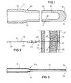
- the catheter 10 shown in FIG. 1 is an epidural catheter, used in regional anesthesia to be a local anesthetic e.g. to inject into the epidural space.
- the catheter 10 consists of an elongated tube 11 from above the length of the same material throughout.
- the hose 11 has a proximal tube section 12 and a distal one Hose section 13 on.
- the catheter has a total length 1000 mm.
- the outer diameter of the proximal tube section 12 is 0.85 mm and the inside diameter is 0.45 mm.
- this information is only an example. Of course, other dimensions are possible.
- the distal tube section 13 has a length of at least 10 mm.
- the outer diameter is in the distal tube section 13 to about 80% of the outer diameter of the proximal tube section reduced. This reduction is done by stretching, wherein a transition region 14 is formed.
- the stretching takes place by pulling the tube long, its proximal tube section 12 is held by a clamping device while the distal tube section 13 is elongated becomes.
- a corresponding Thorn can be used.
- pulling the distal tube section 13 reduces its wall thickness by transverse contraction.
- the catheter tip 15 At the distal end of the distal tube section 13 is the catheter tip 15, in the present Embodiment by an existing from the catheter material round end cap 16 is formed. Alternatively to this is also a central opening at the catheter tip possible.
- the catheter 10 of Fig. 1 is near the catheter tip lateral openings at the distal tube sections 17 attached through the liquid leak from the catheter can.
- Fig. 2 the use of the catheter 10 as an epidural catheter shown.
- the catheter 10 is used in conjunction with a Tuohy cannula 20 used.
- This has a steel cannula 21, which is provided at its proximal end with a needle hub 22 is.
- the distal end of the cannula is provided with a bend 23.
- the cannula 20 is in the manner shown in Fig. 2 through the skin 24, between the vertebrae 25 of the spine through the ligamentum flavum 26 into the epidural space 27 advanced. Then it passes through the cannula 20 the catheter 10 pushed by the curved cannula end 23 is angled and advanced in the epidural space 27.
- the tapered distal catheter section 13 has a length of about 5 cm in this embodiment. This length corresponds to the length that passes over the cannula end 23 protrudes into the epidural space.
- markings 28 are attached, with where the insertion depth of the catheter can be determined.
- Fig. 3 shows a catheter 10a serving as a central venous catheter is trained.
- This catheter is passed through a central vein through to the immediate vicinity of the heart, the catheter tip 15 initially under ECG position control advanced into the right atrium and then in the Vena cava is pulled back into it. In the vena cava is then injected a drug through the catheter.
- the catheter contains a guidewire whose tip is at the catheter tip 15 exit. The derivation of the ECG signals via the guidewire.
- the total length of the catheter 10a is central venous Catheter about 15 cm.
- the catheter 10 a has a proximal tube section 12 and a tapered distal tube section 13, which are both made of the same material throughout.
- the distal tube section 13 has a length of at least 10 centimeters.
- the catheter 10a is connected to a Y-piece 30, of which two branches 31 and 32 go off.
- the branch 31 is with connected to a catheter hub 33 and the junction 32 is with connected to a catheter hub 34.
- Each of the branches 31 and 32 has a hose clamp 35.
- a guide wire 36 which at the distal end an easily deformable curved tip 37 having.
- the tip 37 protrudes from the catheter tip 15.
- a contact terminal 38 To the protruding from the catheter hub 33 distal end of Guide wire 36 is a contact terminal 38, a cable 39th connected, which is connected to an ECG display device can be. In this way can be determined by ECG control Be sure the catheter tip is in the right atrium or located in the vena cava.
- the guide wire 36 has a diameter such that it without substantial friction through the distal tube section 13 can be pushed. He enters at the central opening the catheter tip 15 off. The opening edges are rounded.
- the catheter 10a used in the present embodiment has a single lumen can also be executed Periodicg. By stretching the distal tube section all Lumen reduced in diameter.
- the catheter persists throughout its entire length the same material. He can, however, also two or more layers be formed and an inner tube and an outer tube wherein the catheter, in particular by coextrusion Both tubes can be produced.
- the material combination is particularly suitable PA-PU, wherein the inner tube of polyamide and the Outer tube made of polyurethane.
- PA-PU for a central venous Catheter is particularly suitable a combination of materials PU-PU made of different polyurethanes and for a venous indwelling cannula a combination of materials PA-PA from different Polyamides.
Landscapes
- Health & Medical Sciences (AREA)
- Life Sciences & Earth Sciences (AREA)
- Biophysics (AREA)
- Pulmonology (AREA)
- Engineering & Computer Science (AREA)
- Anesthesiology (AREA)
- Biomedical Technology (AREA)
- Heart & Thoracic Surgery (AREA)
- Hematology (AREA)
- Animal Behavior & Ethology (AREA)
- General Health & Medical Sciences (AREA)
- Public Health (AREA)
- Veterinary Medicine (AREA)
- Media Introduction/Drainage Providing Device (AREA)
- Infusion, Injection, And Reservoir Apparatuses (AREA)
Abstract
Description
- Fig. 1
- einen Längsschnitt durch einen Epiduralkatheter nach der vorliegenden Erfindung mit geschlossener Katheterspitze,
- Fig. 2
- eine Verwendung des Katheters nach Fig. 1 in Verbindung mit einer Tuohy-Kanüle,
- Fig. 3
- einen Längsschnitt durch einen zentralvenösen Katheter, und
- Fig. 4
- eine Gesamtdarstellung des zentralvenösen Katheters.
Claims (10)
- Katheter bestehend aus einem langgestreckten Schlauch (11) aus in Längsrichtung über die Schlauchlänge durchgehend gleichem Material, mit einem proximalen Schlauchabschnitt (12) und einem distalen Schlauchabschnitt (13),
dadurch gekennzeichnet, dass der distale Schlauchabschnitt (13) relativ zu dem proximalen Schlauchabschnitt (12) einen verringerten Außendurchmesser aufweist. - Katheter nach Anspruch 1, dadurch gekennzeichnet, dass der distale Schlauchabschnitt (13) im Wesentlichen zylindrisch ist.
- Katheter nach Anspruch 1 oder 2, dadurch gekennzeichnet, dass der distale Schlauchabschnitt (13) eine Länge hat, die mindestens gleich dem Fünffachen, vorzugsweise mindestens gleich dem Zehnfachen, des Außendurchmessers des proximalen Schlauchabschnitts (12) ist.
- Katheter nach einem der Ansprüche 1 - 3, dadurch gekennzeichnet, dass die Katheterspitze (15) eine zentrale Öffnung (40) mit verrundeter Kante aufweist.
- Katheter nach einem der Ansprüche 1 - 3, dadurch gekennzeichnet, dass die Katheterspitze (15) eine aus dem Kathetermaterial bestehende runde Abschlusskappe (16) aufweist.
- Katheter nach einem der Ansprüche 1 - 5, dadurch gekennzeichnet, dass der Außendurchmesser des distalen Schlauchabschnitts (13) 50 - 90 % des Außendurchmessers des proximalen Schlauchabschnitts (12) beträgt.
- Katheter nach einem der Ansprüche 1 - 6, dadurch gekennzeichnet, dass der Schlauch (11) aus einem Verbundmaterial mit einem Außenrohr aus PU und einem Innenrohr aus PU oder PA besteht.
- Katheter nach einem der Ansprüche 1 - 7, dadurch gekennzeichnet, dass der Katheter ein Regionalanästhesiekatheter ist, der in einer Regionalanästhesiekanüle (21) verschiebbar ist.
- Katheter nach einem der Ansprüche 1 - 7, dadurch gekennzeichnet, dass der Katheter ein zentralvenöser Katheter (10a) ist, der einen Führungsdraht (36) enthält und ein Y-Stück (30) mit mindestens zwei Abzweigungen (31, 32) aufweist.
- Katheter nach einem der Ansprüche 1 - 7, dadurch gekennzeichnet, dass der Katheter ein Venenverweilkatheter ist, der einen Katheteransatz aufweist und auf eine Stahlkanüle aufschiebbar ist.
Applications Claiming Priority (2)
| Application Number | Priority Date | Filing Date | Title |
|---|---|---|---|
| DE20110121U | 2001-06-19 | ||
| DE20110121U DE20110121U1 (de) | 2001-06-19 | 2001-06-19 | Katheter |
Publications (2)
| Publication Number | Publication Date |
|---|---|
| EP1270039A1 true EP1270039A1 (de) | 2003-01-02 |
| EP1270039B1 EP1270039B1 (de) | 2006-11-08 |
Family
ID=7958255
Family Applications (1)
| Application Number | Title | Priority Date | Filing Date |
|---|---|---|---|
| EP02011910A Expired - Lifetime EP1270039B1 (de) | 2001-06-19 | 2002-05-29 | Katheter |
Country Status (5)
| Country | Link |
|---|---|
| US (2) | US7601138B2 (de) |
| EP (1) | EP1270039B1 (de) |
| JP (1) | JP4231246B2 (de) |
| DE (2) | DE20110121U1 (de) |
| ES (1) | ES2272608T3 (de) |
Families Citing this family (37)
| Publication number | Priority date | Publication date | Assignee | Title |
|---|---|---|---|---|
| CA2433269A1 (en) * | 2002-06-25 | 2003-12-25 | Kieran P. Murphy | Surgical chair for percutaneous spinal catheter insertion |
| US8078274B2 (en) | 2003-02-21 | 2011-12-13 | Dtherapeutics, Llc | Device, system and method for measuring cross-sectional areas in luminal organs |
| US10172538B2 (en) | 2003-02-21 | 2019-01-08 | 3Dt Holdings, Llc | Body lumen junction localization |
| US10413211B2 (en) | 2003-02-21 | 2019-09-17 | 3Dt Holdings, Llc | Systems, devices, and methods for mapping organ profiles |
| US7818053B2 (en) | 2003-02-21 | 2010-10-19 | Dtherapeutics, Llc | Devices, systems and methods for plaque type determination |
| DE102004008709A1 (de) * | 2004-02-23 | 2005-09-08 | Walter Hutzler | Blasenkatheter |
| US20060116636A1 (en) * | 2004-11-30 | 2006-06-01 | Murphy Kieran P | Self-sealing catheter for deformable tissue |
| JP2008084546A (ja) * | 2006-09-25 | 2008-04-10 | Gifu Univ | 電線及びカテーテル |
| US8573218B2 (en) * | 2007-03-07 | 2013-11-05 | Michael John RUTTER | Tracheostomy tube |
| CH699220A1 (de) * | 2008-07-16 | 2010-01-29 | Schwager Medica | Verfahren zum Verbinden von Kunststoffröhrchen. |
| DE102009007352B4 (de) * | 2009-02-04 | 2011-02-03 | Wienerberger Gmbh | Vorrichtung zum Eindecken einer Unterkonstruktion |
| US8986283B2 (en) | 2011-05-18 | 2015-03-24 | Solo-Dex, Llc | Continuous anesthesia nerve conduction apparatus, system and method thereof |
| WO2012159000A2 (en) | 2011-05-18 | 2012-11-22 | Solodex Llc | Continuous anesthesia nerve conduction apparatus, system and method |
| WO2013100987A1 (en) | 2011-12-28 | 2013-07-04 | Custom Medical Applications, Inc. | Catheters including bend indicators, catheter assemblies including such catheters and related methods |
| US10159531B2 (en) | 2012-04-05 | 2018-12-25 | C. R. Bard, Inc. | Apparatus and methods relating to intravascular positioning of distal end of catheter |
| US11759268B2 (en) | 2012-04-05 | 2023-09-19 | C. R. Bard, Inc. | Apparatus and methods relating to intravascular positioning of distal end of catheter |
| AU2013243252B2 (en) | 2012-04-05 | 2017-04-06 | Bard Access Systems, Inc. | Devices and systems for navigation and positioning a central venous catheter within a patient |
| US20140142497A1 (en) * | 2012-08-13 | 2014-05-22 | Michael Esposito | Bowed tip for laparoscopic surgery |
| US9440045B2 (en) | 2013-02-01 | 2016-09-13 | Cook Medical Technologies Llc | Curved tip hemodialysis catheter |
| CN108135591B (zh) | 2016-02-24 | 2021-05-28 | 禾木(中国)生物工程有限公司 | 柔性增强的神经血管导管 |
| JP7264581B2 (ja) | 2017-01-06 | 2023-04-25 | インセプト、リミテッド、ライアビリティ、カンパニー | 動脈瘤治療装置向けの抗血栓性コーティング |
| US20180245974A1 (en) * | 2017-01-26 | 2018-08-30 | Truly Green Solutions, LLC | Method for measuring light for led replacement |
| CN119405388A (zh) | 2018-05-01 | 2025-02-11 | 因赛普特有限责任公司 | 用于从血管内部位去除闭塞性物质的装置和方法 |
| US11395665B2 (en) | 2018-05-01 | 2022-07-26 | Incept, Llc | Devices and methods for removing obstructive material, from an intravascular site |
| US11517335B2 (en) | 2018-07-06 | 2022-12-06 | Incept, Llc | Sealed neurovascular extendable catheter |
| US11471582B2 (en) | 2018-07-06 | 2022-10-18 | Incept, Llc | Vacuum transfer tool for extendable catheter |
| US11766539B2 (en) | 2019-03-29 | 2023-09-26 | Incept, Llc | Enhanced flexibility neurovascular catheter |
| EP4044906B1 (de) | 2019-10-15 | 2025-03-12 | Kandu Health, Inc. | Systeme und verfahren zur mehrgrössenhubdetektion |
| JP2023507553A (ja) | 2019-12-18 | 2023-02-24 | インパラティブ、ケア、インク. | 静脈血栓塞栓症を治療するための方法及びシステム |
| US20230248498A1 (en) | 2019-12-18 | 2023-08-10 | Imperative Care, Inc. | Manually rotatable thrombus engagement tool |
| US11633272B2 (en) | 2019-12-18 | 2023-04-25 | Imperative Care, Inc. | Manually rotatable thrombus engagement tool |
| US11457936B2 (en) | 2019-12-18 | 2022-10-04 | Imperative Care, Inc. | Catheter system for treating thromboembolic disease |
| WO2021183444A1 (en) | 2020-03-10 | 2021-09-16 | Imperative Care, Inc. | Enhanced flexibility neurovascular catheter |
| US12558175B2 (en) | 2021-08-12 | 2026-02-24 | Imperative Care, Inc. | Multi catheter method of performing a robotic neurovascular procedure |
| USD1077996S1 (en) | 2021-10-18 | 2025-06-03 | Imperative Care, Inc. | Inline fluid filter |
| JP2023109491A (ja) * | 2022-01-27 | 2023-08-08 | ニプロ株式会社 | 胚移植用カテーテル |
| US12171917B1 (en) | 2024-01-08 | 2024-12-24 | Imperative Care, Inc. | Devices for blood capture and reintroduction during aspiration procedure |
Citations (6)
| Publication number | Priority date | Publication date | Assignee | Title |
|---|---|---|---|---|
| US4639252A (en) * | 1985-04-05 | 1987-01-27 | Research Medical, Inc. | Venous return catheter |
| EP0452123A1 (de) * | 1990-04-11 | 1991-10-16 | Becton, Dickinson and Company | Strahlungsundurchlässiges, optisch transparentes, medizinisches Rohr |
| US5234406A (en) * | 1992-04-06 | 1993-08-10 | The Regents Of The University Of California | Method and system for continuous spinal delivery of anesthetics |
| US5830196A (en) * | 1995-09-21 | 1998-11-03 | Tyco Group S.A.R.L. | Tapered and reinforced catheter |
| WO1999042156A1 (en) * | 1998-02-24 | 1999-08-26 | Boston Scientific Limited | High flow rate dialysis catheters and related methods |
| US6221059B1 (en) * | 1996-06-21 | 2001-04-24 | Medtronic, Inc. | Flow-directed catheter system and method of use |
Family Cites Families (54)
| Publication number | Priority date | Publication date | Assignee | Title |
|---|---|---|---|---|
| NL281166A (de) * | 1961-07-29 | |||
| US3885561A (en) * | 1971-12-15 | 1975-05-27 | Charles N Mazal Cami | Catheter |
| US4211233A (en) * | 1978-01-05 | 1980-07-08 | Lin Edward D | Urethral catheter |
| US4381008A (en) * | 1978-09-08 | 1983-04-26 | Johnson & Johnson | Methods of improving surface characteristics of extruded thermoplastic tubing and products produced thereby |
| US4283447A (en) * | 1979-05-18 | 1981-08-11 | Flynn Vincent J | Radiopaque polyurethane resin compositions |
| DE3117802A1 (de) * | 1981-05-06 | 1982-11-25 | Max Dr. 8520 Erlangen Hubmann | Katheterbesteck |
| US4411655A (en) * | 1981-11-30 | 1983-10-25 | Schreck David M | Apparatus and method for percutaneous catheterization |
| US4557721A (en) * | 1983-11-29 | 1985-12-10 | Cordis Corporation | Servo valve |
| US4551292A (en) * | 1984-04-05 | 1985-11-05 | Angiomedics, Inc. | Method for making a catheter with a soft, deformable tip |
| US5180387A (en) * | 1987-09-17 | 1993-01-19 | Neurodynamics, Inc. | Angled hole ventricular catheter with non-circular bore |
| US4985022A (en) * | 1988-11-23 | 1991-01-15 | Med Institute, Inc. | Catheter having durable and flexible segments |
| DE3922406C1 (de) * | 1989-07-07 | 1990-10-11 | B. Braun Melsungen Ag, 3508 Melsungen, De | |
| NL9000054A (nl) | 1990-01-09 | 1991-08-01 | Cordis Europ | Werkwijze voor het vervaardigen van een catheter. |
| US5688246A (en) * | 1991-04-19 | 1997-11-18 | Biotime, Inc. | Microcannula |
| CA2073608A1 (en) | 1991-07-12 | 1993-01-13 | Kenneth B. Wagener | Kink resistant, flexible, radiopaque polyurethane tubing and catheters formed therefrom |
| US5308342A (en) * | 1991-08-07 | 1994-05-03 | Target Therapeutics, Inc. | Variable stiffness catheter |
| US6652492B1 (en) * | 1991-12-13 | 2003-11-25 | Endovascular Technologies, Inc. | Dual valve, flexible sheath and method |
| FR2691069B1 (fr) * | 1992-05-14 | 1999-08-20 | Vygon | Instrument chirurgical pour operation d'anesthesie peridurale. |
| DE4316330C2 (de) * | 1993-01-28 | 2000-07-27 | Angiomed Ag | Einstückiges konisches Führungsteil zur Katheterisierung und Verfahren zur Herstellung desselben |
| AU669026B2 (en) * | 1993-01-29 | 1996-05-23 | Becton Dickinson & Company | Catheter/needle assembly kit and method for administering therapeutic agents to the subarachnoid space |
| EP0689466B1 (de) * | 1993-03-16 | 1997-05-28 | Med-Pro Design, Inc. | Katheter und herstellungsverfahren |
| JP3383009B2 (ja) * | 1993-06-29 | 2003-03-04 | テルモ株式会社 | 血管カテーテル |
| NL9301642A (nl) * | 1993-09-22 | 1995-04-18 | Cordis Europ | Microcatheter. |
| US5533985A (en) * | 1994-04-20 | 1996-07-09 | Wang; James C. | Tubing |
| AU2372295A (en) * | 1994-04-29 | 1995-11-29 | Target Therapeutics, Inc. | Method for producing lubricious catheters |
| US5496294A (en) * | 1994-07-08 | 1996-03-05 | Target Therapeutics, Inc. | Catheter with kink-resistant distal tip |
| US5531700A (en) * | 1994-07-29 | 1996-07-02 | Cardiovascular Imaging Systems, Inc. | Convertible tip catheters and sheaths |
| US5599326A (en) * | 1994-12-20 | 1997-02-04 | Target Therapeutics, Inc. | Catheter with multi-layer section |
| US5702372A (en) * | 1995-02-08 | 1997-12-30 | Medtronic, Inc. | Lined infusion catheter |
| US5614136A (en) * | 1995-03-02 | 1997-03-25 | Scimed Life Systems, Inc. | Process to form dimensionally variable tubular members for use in catheter procedures |
| US5752930A (en) * | 1995-04-28 | 1998-05-19 | Medtronic, Inc. | Implantable techniques for infusing equal volumes of agents to spaced sites |
| AU693357B2 (en) * | 1995-04-28 | 1998-06-25 | Target Therapeutics, Inc. | High performance braided catheter |
| US5700252A (en) * | 1995-11-01 | 1997-12-23 | Klingenstein; Ralph James | Lumen-seeking nasogastric tube and method |
| US5843050A (en) * | 1995-11-13 | 1998-12-01 | Micro Therapeutics, Inc. | Microcatheter |
| JP3304345B2 (ja) * | 1995-12-04 | 2002-07-22 | ニプロ株式会社 | 留置針外針およびその製造方法 |
| US5846220A (en) * | 1996-04-30 | 1998-12-08 | Medtronic, Inc. | Therapeutic method for treatment of Alzheimer's disease |
| US5782811A (en) * | 1996-05-30 | 1998-07-21 | Target Therapeutics, Inc. | Kink-resistant braided catheter with distal side holes |
| US5971975A (en) * | 1996-10-09 | 1999-10-26 | Target Therapeutics, Inc. | Guide catheter with enhanced guidewire tracking |
| US6258079B1 (en) * | 1997-01-21 | 2001-07-10 | Vasca, Inc. | Method and systems for establishing vascular access |
| US5938653A (en) * | 1997-06-09 | 1999-08-17 | Scimed Life Systems, Inc. | Catheter having controlled flexibility and method of manufacture |
| US5947940A (en) * | 1997-06-23 | 1999-09-07 | Beisel; Robert F. | Catheter reinforced to prevent luminal collapse and tensile failure thereof |
| US6030369A (en) * | 1997-07-03 | 2000-02-29 | Target Therapeutics Inc. | Micro catheter shaft |
| US6295990B1 (en) * | 1998-02-03 | 2001-10-02 | Salient Interventional Systems, Inc. | Methods and systems for treating ischemia |
| US6622367B1 (en) * | 1998-02-03 | 2003-09-23 | Salient Interventional Systems, Inc. | Intravascular device and method of manufacture and use |
| GB9807856D0 (en) * | 1998-04-15 | 1998-06-10 | Smiths Industries Plc | Medico-surgical tubes and methods of manufacture |
| US6045547A (en) * | 1998-06-15 | 2000-04-04 | Scimed Life Systems, Inc. | Semi-continuous co-extruded catheter shaft |
| US6355027B1 (en) * | 1999-06-09 | 2002-03-12 | Possis Medical, Inc. | Flexible microcatheter |
| US6350253B1 (en) * | 1999-07-19 | 2002-02-26 | I-Flow Corporation | Catheter for uniform delivery of medication |
| US6596235B2 (en) * | 1999-09-30 | 2003-07-22 | Therox, Inc. | Method for blood oxygenation |
| DE10012852A1 (de) * | 2000-03-16 | 2001-09-20 | Angiomed Ag | Kathetersystem zum Zuführen flexibler Stents |
| US6579484B1 (en) * | 1999-12-16 | 2003-06-17 | Advanced Cardiovascular Systems, Inc. | Co-extruded taper shaft |
| DE20009204U1 (de) * | 2000-05-22 | 2000-08-17 | Jomed GmbH, 72414 Rangendingen | Katheteranordnung zur Stentimplantation |
| US6663614B1 (en) * | 2000-11-06 | 2003-12-16 | Advanced Cardiovascular Systems, Inc. | Catheter shaft having variable thickness layers and method of making |
| US6533751B2 (en) * | 2001-01-09 | 2003-03-18 | Andrew Cragg | Micro catheter and guidewire system having improved pushability and control |
-
2001
- 2001-06-19 DE DE20110121U patent/DE20110121U1/de not_active Expired - Lifetime
-
2002
- 2002-05-29 ES ES02011910T patent/ES2272608T3/es not_active Expired - Lifetime
- 2002-05-29 DE DE50208638T patent/DE50208638D1/de not_active Expired - Lifetime
- 2002-05-29 EP EP02011910A patent/EP1270039B1/de not_active Expired - Lifetime
- 2002-06-18 US US10/175,455 patent/US7601138B2/en not_active Expired - Lifetime
- 2002-06-19 JP JP2002178724A patent/JP4231246B2/ja not_active Expired - Fee Related
-
2007
- 2007-10-19 US US11/875,296 patent/US7763196B2/en not_active Expired - Lifetime
Patent Citations (6)
| Publication number | Priority date | Publication date | Assignee | Title |
|---|---|---|---|---|
| US4639252A (en) * | 1985-04-05 | 1987-01-27 | Research Medical, Inc. | Venous return catheter |
| EP0452123A1 (de) * | 1990-04-11 | 1991-10-16 | Becton, Dickinson and Company | Strahlungsundurchlässiges, optisch transparentes, medizinisches Rohr |
| US5234406A (en) * | 1992-04-06 | 1993-08-10 | The Regents Of The University Of California | Method and system for continuous spinal delivery of anesthetics |
| US5830196A (en) * | 1995-09-21 | 1998-11-03 | Tyco Group S.A.R.L. | Tapered and reinforced catheter |
| US6221059B1 (en) * | 1996-06-21 | 2001-04-24 | Medtronic, Inc. | Flow-directed catheter system and method of use |
| WO1999042156A1 (en) * | 1998-02-24 | 1999-08-26 | Boston Scientific Limited | High flow rate dialysis catheters and related methods |
Also Published As
| Publication number | Publication date |
|---|---|
| ES2272608T3 (es) | 2007-05-01 |
| EP1270039B1 (de) | 2006-11-08 |
| US7763196B2 (en) | 2010-07-27 |
| JP4231246B2 (ja) | 2009-02-25 |
| US7601138B2 (en) | 2009-10-13 |
| JP2003019206A (ja) | 2003-01-21 |
| DE50208638D1 (de) | 2006-12-21 |
| US20030018317A1 (en) | 2003-01-23 |
| DE20110121U1 (de) | 2002-12-05 |
| US20080045927A1 (en) | 2008-02-21 |
Similar Documents
| Publication | Publication Date | Title |
|---|---|---|
| EP1270039B1 (de) | Katheter | |
| DE69013532T2 (de) | Aus einem abgestuften Dilator und einer Hülle bestehende Einheit und Verfahren zu deren Herstellung. | |
| DE69320136T2 (de) | Verbesserter gallenkatheter | |
| DE69201874T2 (de) | Intravaskulärer mehrlumiger Katheter für das Implantieren mit Hilfe eines Tunnels. | |
| DE69632852T2 (de) | Teleskopischer katheter | |
| DE2238722C3 (de) | Katheter | |
| DE68911734T2 (de) | Schutzhülle für Katheter. | |
| DE69212717T2 (de) | Kathetervorrichtung mit Katheter- und Führungsdrahtwechsel | |
| DE69529806T2 (de) | Katheter mit Mehrschichtbereich | |
| DE69122582T2 (de) | Drainagekatheter | |
| DE3751869T2 (de) | Katheter-sonde | |
| DE69123817T2 (de) | Gerät zum Abdichten von Punkturwunden | |
| DE60310949T2 (de) | Drainagekatheter | |
| DE68918092T2 (de) | Führungsdraht für katheter. | |
| DE69731979T2 (de) | Dialysekatheter mit starren und kollabierbaren lumina | |
| DE60225063T2 (de) | Hypotube mit verbesserter zugentlastung für einen katheter | |
| DE69416332T2 (de) | Einführungsstilett für medizinsche kanüle und kanüle | |
| DE69935697T2 (de) | Katheteranordnung zum Implantieren von Embryos und Verfahren zur Herstellung | |
| EP0362494A1 (de) | Katheterset für die Spinalanästhesie | |
| DE2015524A1 (de) | Intravaskuläre Kathetereinrichtung | |
| EP0679408A2 (de) | Vorrichtung zum Einführen eines Katheters in einen Körperhohlraum | |
| DE2121699B2 (de) | Injektionsnadel aus Metall mit Kupplungsteil | |
| DE102015117923A1 (de) | Punktionssystem | |
| EP0102498B1 (de) | Katheterset | |
| DE3788122T2 (de) | System zum wechseln von kathetern von aussen. |
Legal Events
| Date | Code | Title | Description |
|---|---|---|---|
| PUAI | Public reference made under article 153(3) epc to a published international application that has entered the european phase |
Free format text: ORIGINAL CODE: 0009012 |
|
| AK | Designated contracting states |
Kind code of ref document: A1 Designated state(s): AT BE CH CY DE DK ES FI FR GB GR IE IT LI LU MC NL PT SE TR |
|
| AX | Request for extension of the european patent |
Free format text: AL;LT;LV;MK;RO;SI |
|
| 17P | Request for examination filed |
Effective date: 20030618 |
|
| AKX | Designation fees paid |
Designated state(s): DE ES FR GB IT |
|
| 17Q | First examination report despatched |
Effective date: 20031230 |
|
| GRAP | Despatch of communication of intention to grant a patent |
Free format text: ORIGINAL CODE: EPIDOSNIGR1 |
|
| GRAS | Grant fee paid |
Free format text: ORIGINAL CODE: EPIDOSNIGR3 |
|
| GRAA | (expected) grant |
Free format text: ORIGINAL CODE: 0009210 |
|
| AK | Designated contracting states |
Kind code of ref document: B1 Designated state(s): DE ES FR GB IT |
|
| REG | Reference to a national code |
Ref country code: GB Ref legal event code: FG4D Free format text: NOT ENGLISH |
|
| REF | Corresponds to: |
Ref document number: 50208638 Country of ref document: DE Date of ref document: 20061221 Kind code of ref document: P |
|
| GBT | Gb: translation of ep patent filed (gb section 77(6)(a)/1977) |
Effective date: 20070214 |
|
| ET | Fr: translation filed | ||
| REG | Reference to a national code |
Ref country code: ES Ref legal event code: FG2A Ref document number: 2272608 Country of ref document: ES Kind code of ref document: T3 |
|
| PLBE | No opposition filed within time limit |
Free format text: ORIGINAL CODE: 0009261 |
|
| STAA | Information on the status of an ep patent application or granted ep patent |
Free format text: STATUS: NO OPPOSITION FILED WITHIN TIME LIMIT |
|
| 26N | No opposition filed |
Effective date: 20070809 |
|
| REG | Reference to a national code |
Ref country code: FR Ref legal event code: PLFP Year of fee payment: 15 |
|
| REG | Reference to a national code |
Ref country code: FR Ref legal event code: PLFP Year of fee payment: 16 |
|
| REG | Reference to a national code |
Ref country code: FR Ref legal event code: PLFP Year of fee payment: 17 |
|
| PGFP | Annual fee paid to national office [announced via postgrant information from national office to epo] |
Ref country code: FR Payment date: 20210525 Year of fee payment: 20 Ref country code: DE Payment date: 20210525 Year of fee payment: 20 Ref country code: IT Payment date: 20210531 Year of fee payment: 20 |
|
| PGFP | Annual fee paid to national office [announced via postgrant information from national office to epo] |
Ref country code: GB Payment date: 20210526 Year of fee payment: 20 Ref country code: ES Payment date: 20210618 Year of fee payment: 20 |
|
| REG | Reference to a national code |
Ref country code: DE Ref legal event code: R071 Ref document number: 50208638 Country of ref document: DE |
|
| REG | Reference to a national code |
Ref country code: GB Ref legal event code: PE20 Expiry date: 20220528 |
|
| REG | Reference to a national code |
Ref country code: ES Ref legal event code: FD2A Effective date: 20220629 |
|
| PG25 | Lapsed in a contracting state [announced via postgrant information from national office to epo] |
Ref country code: GB Free format text: LAPSE BECAUSE OF EXPIRATION OF PROTECTION Effective date: 20220528 Ref country code: ES Free format text: LAPSE BECAUSE OF EXPIRATION OF PROTECTION Effective date: 20220530 |