EP1267022A2 - Notverriegelungseinrichtung - Google Patents
Notverriegelungseinrichtung Download PDFInfo
- Publication number
- EP1267022A2 EP1267022A2 EP02010810A EP02010810A EP1267022A2 EP 1267022 A2 EP1267022 A2 EP 1267022A2 EP 02010810 A EP02010810 A EP 02010810A EP 02010810 A EP02010810 A EP 02010810A EP 1267022 A2 EP1267022 A2 EP 1267022A2
- Authority
- EP
- European Patent Office
- Prior art keywords
- locking
- locking lever
- lever
- recess
- locking device
- Prior art date
- Legal status (The legal status is an assumption and is not a legal conclusion. Google has not performed a legal analysis and makes no representation as to the accuracy of the status listed.)
- Granted
Links
Images


Classifications
-
- E—FIXED CONSTRUCTIONS
- E05—LOCKS; KEYS; WINDOW OR DOOR FITTINGS; SAFES
- E05B—LOCKS; ACCESSORIES THEREFOR; HANDCUFFS
- E05B81/00—Power-actuated vehicle locks
- E05B81/54—Electrical circuits
- E05B81/90—Manual override in case of power failure
-
- Y—GENERAL TAGGING OF NEW TECHNOLOGICAL DEVELOPMENTS; GENERAL TAGGING OF CROSS-SECTIONAL TECHNOLOGIES SPANNING OVER SEVERAL SECTIONS OF THE IPC; TECHNICAL SUBJECTS COVERED BY FORMER USPC CROSS-REFERENCE ART COLLECTIONS [XRACs] AND DIGESTS
- Y10—TECHNICAL SUBJECTS COVERED BY FORMER USPC
- Y10S—TECHNICAL SUBJECTS COVERED BY FORMER USPC CROSS-REFERENCE ART COLLECTIONS [XRACs] AND DIGESTS
- Y10S292/00—Closure fasteners
- Y10S292/23—Vehicle door latches
-
- Y—GENERAL TAGGING OF NEW TECHNOLOGICAL DEVELOPMENTS; GENERAL TAGGING OF CROSS-SECTIONAL TECHNOLOGIES SPANNING OVER SEVERAL SECTIONS OF THE IPC; TECHNICAL SUBJECTS COVERED BY FORMER USPC CROSS-REFERENCE ART COLLECTIONS [XRACs] AND DIGESTS
- Y10—TECHNICAL SUBJECTS COVERED BY FORMER USPC
- Y10S—TECHNICAL SUBJECTS COVERED BY FORMER USPC CROSS-REFERENCE ART COLLECTIONS [XRACs] AND DIGESTS
- Y10S292/00—Closure fasteners
- Y10S292/53—Mounting and attachment
-
- Y—GENERAL TAGGING OF NEW TECHNOLOGICAL DEVELOPMENTS; GENERAL TAGGING OF CROSS-SECTIONAL TECHNOLOGIES SPANNING OVER SEVERAL SECTIONS OF THE IPC; TECHNICAL SUBJECTS COVERED BY FORMER USPC CROSS-REFERENCE ART COLLECTIONS [XRACs] AND DIGESTS
- Y10—TECHNICAL SUBJECTS COVERED BY FORMER USPC
- Y10T—TECHNICAL SUBJECTS COVERED BY FORMER US CLASSIFICATION
- Y10T292/00—Closure fasteners
- Y10T292/08—Bolts
- Y10T292/1043—Swinging
- Y10T292/1044—Multiple head
- Y10T292/1045—Operating means
- Y10T292/1047—Closure
-
- Y—GENERAL TAGGING OF NEW TECHNOLOGICAL DEVELOPMENTS; GENERAL TAGGING OF CROSS-SECTIONAL TECHNOLOGIES SPANNING OVER SEVERAL SECTIONS OF THE IPC; TECHNICAL SUBJECTS COVERED BY FORMER USPC CROSS-REFERENCE ART COLLECTIONS [XRACs] AND DIGESTS
- Y10—TECHNICAL SUBJECTS COVERED BY FORMER USPC
- Y10T—TECHNICAL SUBJECTS COVERED BY FORMER US CLASSIFICATION
- Y10T292/00—Closure fasteners
- Y10T292/08—Bolts
- Y10T292/1043—Swinging
- Y10T292/1075—Operating means
- Y10T292/1082—Motor
-
- Y—GENERAL TAGGING OF NEW TECHNOLOGICAL DEVELOPMENTS; GENERAL TAGGING OF CROSS-SECTIONAL TECHNOLOGIES SPANNING OVER SEVERAL SECTIONS OF THE IPC; TECHNICAL SUBJECTS COVERED BY FORMER USPC CROSS-REFERENCE ART COLLECTIONS [XRACs] AND DIGESTS
- Y10—TECHNICAL SUBJECTS COVERED BY FORMER USPC
- Y10T—TECHNICAL SUBJECTS COVERED BY FORMER US CLASSIFICATION
- Y10T70/00—Locks
- Y10T70/70—Operating mechanism
- Y10T70/7441—Key
- Y10T70/7915—Tampering prevention or attack defeating
- Y10T70/7955—Keyhole guards
- Y10T70/7977—Key-controlled
Definitions
- the invention relates to an emergency locking device for a motor vehicle door lock, with at least one locking lever, especially central locking lever or locking lever working on the central locking lever, and with a manually operated from the outside Rotary body, which the locking lever in one Locking position of the motor vehicle door lock or locking position shifted.
- Such emergency locking devices usually come then used when a central locking system fails. Because that usually means that everyone Motor vehicle door locks of the motor vehicle in unlocked Condition. To such a motor vehicle to be able to lock (lock) anyway other locking measures are taken. A One possibility is to do this via internal locking buttons to accomplish. This is what happens today increasingly refrained from for theft protection reasons. Besides could be thought of using an associated door Lock cylinder lock. However, this only works with such motor vehicle doors that with a Lock cylinders are equipped. For the rear in particular side doors or tailgates, rear doors etc. usually does not apply.
- the invention is based on the technical problem to further develop such an emergency locking device, that with simple construction manipulations on the associated Motor vehicle door lock can be reliably excluded can.
- the invention proposes Generic emergency locking device for one Motor vehicle door lock that the rotating body as on Locking lever arranged recess for engagement for an actuating tool is formed.
- rotating body and locking lever or central locking lever or safety lever a one-piece component.
- the recess usually has a driving wall for the actuating tool pressed against it. This approach serves to lock the locking lever in the locked position to convict.
- the operating tool it is mostly the key bit of a motor vehicle key. In any case, this operating tool ensures or the key bit by contacting the take-away wall the recess and the corresponding application making sure that the locking lever is in the motor vehicle door lock locking securing position or locking position is shifted.
- the manipulation security of the described emergency locking device has a lock plate of the associated motor vehicle door lock one with the recess congruent in their locking or locking position Opening for engaging the operating tool on.
- the invention recommends that Lock plate with a cover web that plunges into the recess equip which of the driving wall of the recess opposite.
- the relevant lock plate with the opening is located mostly on a tailgate with the motor vehicle door closed or tailgate covered wall. Act on this wall it is regularly the rear face of the door. As a result, the emergency locking device is only open Door or flap accessible. That is reasonable to To be able to rule out manipulation from the outset.
- the invention recommends the emergency locking device overall in the area of an enema mouth to arrange the associated motor vehicle door lock. As a result, the location of the at this point is usually provided provided provided locking lever, which just "behind" the lock plate in the area of the inlet mouth located.
- the recess is usually an im Essentially following the rotary movement of the locking lever Circular segment depression.
- This circular segment depression extends opposite one on the inside of the lock plate adjacent base plate of the locking lever.
- the recess forms in or the unlocking position of the locking lever a slot with the arranged opposite the cover web Driving wall for the operating tool.
- the rest of the area the opening in the lock plate is addressed by the Base plate of the locking lever covered.
- the locking lever with its base plate coplanar to the lock plate is arranged and is pivoted.
- This swivel movement is by a between locking lever and Locking plate arranged bistable toggle spring supports. Because the bistable toggle spring supports both by limited pivoting a stop on the lock plate the locking lever in the locking position as a result of the actuating tool acting on the driving wall as well as by another stop on Lock housing limited pivoting of the locking lever in the unlocked position. For example by actuating the locking cylinder and / or the associated one Internal actuation lever take place as already described has been.
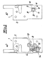
- the motor vehicle door lock 1 has a lock plate 2, on which a locking lever 3 rotatable about an axis 4 is stored.
- the locking lever 3 essentially takes the unlocking position shown in Fig. 1a and the locking position shown in Fig. 2a. there he pivots about axis 4 in a to lock plate 2 coplanar level.
- the locking lever 3 is so at 1b arranged "behind" the lock plate 2, namely in the area of an inlet mouth there.
- the transition from the unlocked to the locked position and back is usually via central locking achieved by not expressly on the locking lever 3 shown central locking lever or a comparable mechanism attacks. If this central locking drive fails, ensures the invention Emergency locking device that the locking lever 3 into the fuse shown in Fig. 2a or locking position can be transferred. For this serves a manually operable from the outside rotating body 5, at which is a arranged on the locking lever 3 Recess 5 for engagement for an operating tool. Usually comes as the actuating tool Key bit of a motor vehicle key for use.
- the lock plate 2 has one with the relevant one Recess 5 in its locking or locking position congruent opening 7.
- the driving wall 6 lies a cover web 8 which plunges into the recess 5 opposite. This cover web 8 is molded onto the lock plate 2 or attached to it.
- the Lock plate 2 with the opening 7 is on one with closed door or flap covered wall, like this is basically described in DE 41 08 561 C2. This wall is mostly congruent with the back wall End face of the associated door, provided it is a rear side door.
- the motor vehicle door lock for example is arranged on a tailgate.
- the concealed arrangement of the lock plate 2 with the Opening 7 and thus the entire emergency locking device with the door or flap closed ensure that the emergency locking device can only be operated if the relevant door or flap is also open. Manipulations are thus excluded because only an authorized vehicle user is able to Open the relevant door or flap (mechanically).
- the recess 5 is a in detail Circular segment depression, which is essentially the rotational movement the locking lever 3 follows, as in the transition from Fig. 1b to Fig. 2b becomes clear.
- This recess 5 or circular segment recess is opposite one on the inside on the lock plate 2 adjacent base plate 9 of the Locking lever 3 realized.
- This base plate 9 is arranged coplanar to the lock plate 2 and is opposite pivoted.
- a bistable toggle spring 12 ensures that both the Locking or securing position of the locking lever 3 (see FIG. 2a) as well as the unlocking or unlocking position (see Fig. 1a) spring-assisted become.
- Associated stops 13, 14 on the lock housing 2 ensure a corresponding limitation of the swiveling path the locking lever 3. The Stop 13 in the unlocked position while the stop 14 unfolds effect in locking or securing position.
Landscapes
- Lock And Its Accessories (AREA)
Abstract
Description
- Fig. 1a und 1b
- einen Kraftfahrzeugtürverschluss mit Zentralverriegelung sowie zugehöriger Notverriegelungseinrichtung in entriegeltem Zustand in einer Ansicht vom Innern des Kraftfahrzeugtürverschlusses aus (Fig. 1a) sowie mit Blick auf die Schlossplatte von außen (Fig. 1b),
- Fig. 2a, 2b
- den Gegenstand nach den Fig. 1a, 1b bei verriegelter Notverriegelungseinrichtung und
- Fig. 3
- den Verriegelungshebel im Detail.
Claims (10)
- Notverriegelungseinrichtung für einen Kraftfahrzeugtürverschluss (1), mit wenigstens einem Verriegelungshebel (3), insbesondere Zentralverriegelungshebel oder auf den Zentralverriegelungshebel arbeitenden Sicherungshebel, und mit einem manuell von außen betätigbaren Drehkörper (5), welcher den Verriegelungshebel (3) in eine den Kraftfahrzeugtürverschluss (1) verriegelnde Sicherungsstellung bzw. Verriegelungsstellung verlagert, dadurch gekennzeichnet, dass der Drehkörper (5) als am Verriegelungshebel (3) angeordnete Ausnehmung (5) zum Eingriff für ein Betätigungswerkzeug ausgebildet ist.
- Notverriegelungseinrichtung nach Anspruch 1, dadurch gekennzeichnet, dass die Ausnehmung (5) eine Mitnahmewand (6) für das hiergegen angedrückte Betätigungswerkzeug aufweist, um den Verriegelungshebel (3) in die Sicherungsstellung zu überführen.
- Notverriegelungseinrichtung nach Anspruch 1 oder 2, dadurch gekennzeichnet, dass eine Schlossplatte (2) eine mit der Ausnehmung (5) in ihrer Sicherungs- bzw. Verriegelungsstellung deckungsgleiche Öffnung (7) zum Eingriff des Betätigungswerkzeuges aufweist.
- Notverriegelungseinrichtung nach einem der Ansprüche 1 bis 3, dadurch gekennzeichnet, dass die Schlossplatte (2) einen in die Ausnehmung (5) eintauchenden Abdecksteg (8) aufweist, welcher der Mitnahmewand (6) der Ausnehmung (5) gegenüberliegt.
- Notverriegelungseinrichtung nach einem der Ansprüche 1 bis 4, dadurch gekennzeichnet, dass die Ausnehmung (5) als im Wesentlichen der Drehbewegung des Verriegelungshebels (3) folgende Kreissegmentvertiefung gegenüber einer innenseitig an der Schlossplatte (2) anliegenden Grundplatte (9) des Verriegelungshebels (3) ausgeführt ist.
- Notverriegelungseinrichtung nach einem der Ansprüche 1 bis 5, dadurch gekennzeichnet, dass die Ausnehmung (5) bei in Entsicherungs- bzw. Entriegelungsstellung befindlichem Verriegelungshebel (3) einen Schlitz mit dem Abdecksteg (8) gegenüberliegend angeordneter Mitnahmewand (6) für das Betätigungswerkzeug bildet.
- Notverriegelungseinrichtung nach einem der Ansprüche 1 bis 6, dadurch gekennzeichnet, dass der Verriegelungshebel (3) mit seiner Grundplatte (9) koplanar zur Schlossplatte (2) angeordnet ist und verschwenkt wird.
- Notverriegelungseinrichtung nach einem der Ansprüche 1 bis 7, dadurch gekennzeichnet, dass zwischen Verriegelungshebel (3) und Schlossplatte (2) eine bistabile Kippfeder (12) angeordnet ist, die sowohl das durch einen Anschlag (14) begrenzte Verschwenken des Verriegelungshebels (3) in die Verriegelungsstellung infolge des an der Mitnahmewand (6) angreifenden Betätigungswerkzeuges als auch das durch einen weiteren Anschlag (13) begrenzte Verschwenken des Verriegelungshebels (3) in die Entriegelungsstellung, z. B. durch Betätigen eines Schließzylinders und/oder eines Innenbetätigungshebels, unterstützt.
- Notverriegelungseinrichtung nach einem der Ansprüche 1 bis 8, dadurch gekennzeichnet, dass sie im Bereich eines Einlaufmauls des Kraftfahrzeugtürverschlusses angeordnet ist.
- Notverriegelungseinrichtung nach einem der Ansprüche 1 bis 9, dadurch gekennzeichnet, dass die Schlossplatte (2) mit der Öffnung (7) an einer bei geschlossener Tür oder Klappe abgedeckten Wand, insbesondere hinteren Stirnfläche der Tür oder Klappe, angeordnet ist.
Applications Claiming Priority (2)
| Application Number | Priority Date | Filing Date | Title |
|---|---|---|---|
| DE10128668 | 2001-06-13 | ||
| DE10128668A DE10128668A1 (de) | 2001-06-13 | 2001-06-13 | Notverriegelungseinrichtung |
Publications (3)
| Publication Number | Publication Date |
|---|---|
| EP1267022A2 true EP1267022A2 (de) | 2002-12-18 |
| EP1267022A3 EP1267022A3 (de) | 2004-02-04 |
| EP1267022B1 EP1267022B1 (de) | 2006-07-19 |
Family
ID=7688140
Family Applications (1)
| Application Number | Title | Priority Date | Filing Date |
|---|---|---|---|
| EP02010810A Expired - Lifetime EP1267022B1 (de) | 2001-06-13 | 2002-05-15 | Notverriegelungseinrichtung |
Country Status (3)
| Country | Link |
|---|---|
| US (1) | US6843517B2 (de) |
| EP (1) | EP1267022B1 (de) |
| DE (2) | DE10128668A1 (de) |
Cited By (2)
| Publication number | Priority date | Publication date | Assignee | Title |
|---|---|---|---|---|
| DE102009001851A1 (de) | 2009-03-25 | 2010-09-30 | Kiekert Ag | Kraftfahrzeug mit Notverrieglungseinrichtung mit Schaltnüssen für mechanische Aussenverrieglung |
| WO2014169889A1 (de) * | 2013-04-16 | 2014-10-23 | Kiekert Aktiengesellschaft | Kraftfahrzeugtürverschluss |
Families Citing this family (5)
| Publication number | Priority date | Publication date | Assignee | Title |
|---|---|---|---|---|
| ES2351747B1 (es) * | 2008-09-16 | 2011-12-05 | Tubsa Automocion, S.L. | Cerradura motorizada de pestillo giratorio. |
| EP2423415A4 (de) * | 2009-04-23 | 2012-12-12 | Aisin Seiki | Türverriegelungsvorrichtung für fahrzeuge |
| WO2012126445A2 (de) | 2011-03-18 | 2012-09-27 | Kiekert Aktiengesellschaft | Kraftfahrzeugtürverschluss |
| JP6450991B2 (ja) * | 2014-10-29 | 2019-01-16 | 三井金属アクト株式会社 | 車両用ドアラッチ装置 |
| DE102019121300A1 (de) | 2019-08-07 | 2021-02-11 | Daimler Ag | Kraftfahrzeugschloss, insbesondere Kraftfahrzeugtürschloss |
Family Cites Families (26)
| Publication number | Priority date | Publication date | Assignee | Title |
|---|---|---|---|---|
| US2034570A (en) * | 1934-09-13 | 1936-03-17 | William A Flavin | Latch device |
| SE398848B (sv) * | 1975-01-17 | 1978-01-23 | Gkn Stenman Ab | Sett att applicera en lasmekanism i en fordonsdorr samt laskasett for genomforande av settet |
| JPS582842Y2 (ja) * | 1977-07-18 | 1983-01-18 | マツダ株式会社 | 自動車用バックドアのロック装置 |
| US4470626A (en) * | 1982-10-22 | 1984-09-11 | General Motors Corporation | Closure latch having an isolated striker |
| US4756563A (en) * | 1986-08-11 | 1988-07-12 | General Motors Corporation | Vehicle door latch |
| DE8809256U1 (de) * | 1988-07-20 | 1988-09-22 | Kiekert GmbH & Co KG, 5628 Heiligenhaus | Kraftfahrzeugtürverschluß mit in der Kraftfahrzeugtür untergebrachtem Schloß und Kindersicherung |
| US5092638B1 (en) * | 1989-06-20 | 1995-04-04 | Mitsui Mining & Smelting Co | Child-lock mechanism for locking apparatus for vehicle |
| US4969673A (en) * | 1989-10-16 | 1990-11-13 | General Motors Corporation | Door latch with block-out type child safety feature |
| DE4108561A1 (de) * | 1991-03-15 | 1992-09-17 | Bayerische Motoren Werke Ag | Schloss mit zentralverriegelungseinrichtung fuer tueren und/oder klappen an kraftfahrzeugen |
| JP2832271B2 (ja) * | 1993-06-25 | 1998-12-09 | 三井金属鉱業株式会社 | スーパーロック機構付アクチュエータ |
| US5537848A (en) * | 1994-06-27 | 1996-07-23 | General Motors Corporation | Deadbolt locking system |
| WO1997003268A1 (en) * | 1995-07-11 | 1997-01-30 | Stoneridge, Inc. | Adjunct actuator for vehicle door lock |
| GB2307506B (en) * | 1995-11-24 | 1999-12-15 | Rockwell Lvs | Vehicle door lock actuator |
| JP3301700B2 (ja) * | 1996-07-10 | 2002-07-15 | 三井金属鉱業株式会社 | 車両用スライド扉の中継機構 |
| US5738394A (en) * | 1996-11-26 | 1998-04-14 | General Motors Corporation | Child-proof door latch |
| JP3430436B2 (ja) * | 1997-03-28 | 2003-07-28 | 株式会社大井製作所 | 自動車用ドアロック装置 |
| US6059328A (en) * | 1997-10-06 | 2000-05-09 | Mitsui Kinzoku Kogyo Kabushiki Kaisha | Vehicle door latch device |
| GB2333319B (en) * | 1998-01-14 | 2002-04-03 | Meritor Light Vehicle Sys Ltd | Vehicle door latch |
| FR2782108B1 (fr) * | 1998-08-05 | 2001-09-28 | Valeo Securite Habitacle | Serrure de fermeture pour une porte de vehicule automobile et vehicule automobile equipe de cette serrure |
| US6045168A (en) * | 1998-10-13 | 2000-04-04 | General Motors Corporation | Door latch with improved double lock |
| US6338508B1 (en) * | 1999-03-24 | 2002-01-15 | Kiekert Ag | Motor-vehicle latch system with power open |
| US6199923B1 (en) * | 1999-06-10 | 2001-03-13 | Delphi Technologies, Inc. | Vehicle door latch |
| DE19943483B4 (de) * | 1999-09-10 | 2008-03-06 | Kiekert Ag | Kraftfahrzeugtürverschluss |
| DE19955882C2 (de) * | 1999-11-20 | 2003-10-23 | Kiekert Ag | Kraftfahrzeugtürverschluss |
| JP3310966B2 (ja) * | 1999-12-28 | 2002-08-05 | 三井金属鉱業株式会社 | アンチセフト機構付車両ドアラッチ装置におけるワンモーション開扉機構 |
| US6517128B2 (en) * | 2001-02-06 | 2003-02-11 | Delphi Technologies, Inc. | Vehicle door latch with power operated release mechanism |
-
2001
- 2001-06-13 DE DE10128668A patent/DE10128668A1/de not_active Ceased
-
2002
- 2002-05-15 DE DE50207538T patent/DE50207538D1/de not_active Expired - Lifetime
- 2002-05-15 EP EP02010810A patent/EP1267022B1/de not_active Expired - Lifetime
- 2002-05-29 US US10/157,768 patent/US6843517B2/en not_active Expired - Fee Related
Cited By (3)
| Publication number | Priority date | Publication date | Assignee | Title |
|---|---|---|---|---|
| DE102009001851A1 (de) | 2009-03-25 | 2010-09-30 | Kiekert Ag | Kraftfahrzeug mit Notverrieglungseinrichtung mit Schaltnüssen für mechanische Aussenverrieglung |
| DE102009001851B4 (de) | 2009-03-25 | 2023-12-07 | Kiekert Aktiengesellschaft | Kraftfahrzeug mit Notverriegelungseinrichtungen mit Schaltnüssen für mechanische Aussenverriegelungen |
| WO2014169889A1 (de) * | 2013-04-16 | 2014-10-23 | Kiekert Aktiengesellschaft | Kraftfahrzeugtürverschluss |
Also Published As
| Publication number | Publication date |
|---|---|
| DE10128668A1 (de) | 2003-01-09 |
| US20020190530A1 (en) | 2002-12-19 |
| EP1267022A3 (de) | 2004-02-04 |
| DE50207538D1 (de) | 2006-08-31 |
| EP1267022B1 (de) | 2006-07-19 |
| US6843517B2 (en) | 2005-01-18 |
Similar Documents
| Publication | Publication Date | Title |
|---|---|---|
| EP1178171B1 (de) | Kraftfahrzeugtürverschluss | |
| DE69307433T2 (de) | Zentralisierter Steuermechanismus mit eingebauten Sicherheiten zur Verwendung in einer abgedichteten Übertragungseinrichtung zwischen zwei geschlossenen Räumen | |
| DE69532799T2 (de) | Verriegelung für einen behälter | |
| DE19632781C2 (de) | Kraftfahrzeug-Türverschluß mit Zentralverriegelungssystem und Diebstahlsicherungssystem | |
| WO2016058590A1 (de) | Kraftfahrzeugtürschloss | |
| DE102022128469A1 (de) | Kraftfahrzeug-Schloss insbesondere Kraftfahrzeug-Türschloss | |
| EP1025325B1 (de) | Verschlussvorrichtung mit einem schlüsselbetätigbaren schliesszylinder, der zugleich als druckhandhabe zum betätigen von schlossgliedern dient | |
| DE1553317C3 (de) | Sperrvorrichtung für eine Kraftfahrzeugtür | |
| WO2001020111A1 (de) | Schliessvorrichtung, insbesondere für kraftfahrzeuge | |
| DE4325693C2 (de) | Türschließeinrichtung | |
| EP1267022B1 (de) | Notverriegelungseinrichtung | |
| DE69416793T2 (de) | Zylinderschloss-Schlüsselkombination | |
| DE4244414C2 (de) | Verschluß für Fenster, Türen u. dgl. | |
| DE4339654C2 (de) | Kraftfahrzeugtürverschluß | |
| DE1678021C3 (de) | ||
| EP0416448B1 (de) | Verschluss, insbesondere für Aussenschwingtüren von Omnibussen | |
| DE202016104019U1 (de) | Schwenkhebelverschluss | |
| DE202013011809U1 (de) | Lenkradschloss für eine Lenksäule für ein Kraftfahrzeug | |
| WO2012126445A2 (de) | Kraftfahrzeugtürverschluss | |
| DE19920329C2 (de) | Container mit Schwerkraftschloß | |
| DE10036398A1 (de) | Vorrichtung zur Arretierung eines Schließzylindergehäuses | |
| DE19538320A1 (de) | Verriegelungsschloß | |
| DE102014115489B4 (de) | Kraftfahrzeugtürverschluss | |
| DE10122368B4 (de) | Schloss | |
| DE2345497C2 (de) | Türverschluß mit Fallen- und Sicherheitsriegel |
Legal Events
| Date | Code | Title | Description |
|---|---|---|---|
| PUAI | Public reference made under article 153(3) epc to a published international application that has entered the european phase |
Free format text: ORIGINAL CODE: 0009012 |
|
| AK | Designated contracting states |
Kind code of ref document: A2 Designated state(s): AT BE CH CY DE DK ES FI FR GB GR IE IT LI LU MC NL PT SE TR |
|
| AX | Request for extension of the european patent |
Free format text: AL;LT;LV;MK;RO;SI |
|
| PUAL | Search report despatched |
Free format text: ORIGINAL CODE: 0009013 |
|
| AK | Designated contracting states |
Kind code of ref document: A3 Designated state(s): AT BE CH CY DE DK ES FI FR GB GR IE IT LI LU MC NL PT SE TR |
|
| AX | Request for extension of the european patent |
Extension state: AL LT LV MK RO SI |
|
| RIC1 | Information provided on ipc code assigned before grant |
Ipc: 7E 05B 65/12 A |
|
| 17P | Request for examination filed |
Effective date: 20040521 |
|
| AKX | Designation fees paid |
Designated state(s): DE FR GB IT |
|
| GRAP | Despatch of communication of intention to grant a patent |
Free format text: ORIGINAL CODE: EPIDOSNIGR1 |
|
| GRAS | Grant fee paid |
Free format text: ORIGINAL CODE: EPIDOSNIGR3 |
|
| GRAA | (expected) grant |
Free format text: ORIGINAL CODE: 0009210 |
|
| AK | Designated contracting states |
Kind code of ref document: B1 Designated state(s): DE FR GB IT |
|
| PG25 | Lapsed in a contracting state [announced via postgrant information from national office to epo] |
Ref country code: IT Free format text: LAPSE BECAUSE OF FAILURE TO SUBMIT A TRANSLATION OF THE DESCRIPTION OR TO PAY THE FEE WITHIN THE PRESCRIBED TIME-LIMIT;WARNING: LAPSES OF ITALIAN PATENTS WITH EFFECTIVE DATE BEFORE 2007 MAY HAVE OCCURRED AT ANY TIME BEFORE 2007. THE CORRECT EFFECTIVE DATE MAY BE DIFFERENT FROM THE ONE RECORDED. Effective date: 20060719 |
|
| REG | Reference to a national code |
Ref country code: GB Ref legal event code: FG4D Free format text: NOT ENGLISH |
|
| REF | Corresponds to: |
Ref document number: 50207538 Country of ref document: DE Date of ref document: 20060831 Kind code of ref document: P |
|
| GBT | Gb: translation of ep patent filed (gb section 77(6)(a)/1977) |
Effective date: 20060821 |
|
| ET | Fr: translation filed | ||
| PLBE | No opposition filed within time limit |
Free format text: ORIGINAL CODE: 0009261 |
|
| STAA | Information on the status of an ep patent application or granted ep patent |
Free format text: STATUS: NO OPPOSITION FILED WITHIN TIME LIMIT |
|
| 26N | No opposition filed |
Effective date: 20070420 |
|
| PGFP | Annual fee paid to national office [announced via postgrant information from national office to epo] |
Ref country code: GB Payment date: 20130522 Year of fee payment: 12 |
|
| PGFP | Annual fee paid to national office [announced via postgrant information from national office to epo] |
Ref country code: IT Payment date: 20130524 Year of fee payment: 12 |
|
| GBPC | Gb: european patent ceased through non-payment of renewal fee |
Effective date: 20140515 |
|
| PG25 | Lapsed in a contracting state [announced via postgrant information from national office to epo] |
Ref country code: IT Free format text: LAPSE BECAUSE OF NON-PAYMENT OF DUE FEES Effective date: 20140515 |
|
| PG25 | Lapsed in a contracting state [announced via postgrant information from national office to epo] |
Ref country code: GB Free format text: LAPSE BECAUSE OF NON-PAYMENT OF DUE FEES Effective date: 20140515 |
|
| REG | Reference to a national code |
Ref country code: FR Ref legal event code: PLFP Year of fee payment: 15 |
|
| REG | Reference to a national code |
Ref country code: FR Ref legal event code: PLFP Year of fee payment: 16 |
|
| REG | Reference to a national code |
Ref country code: FR Ref legal event code: PLFP Year of fee payment: 17 |
|
| PGFP | Annual fee paid to national office [announced via postgrant information from national office to epo] |
Ref country code: FR Payment date: 20210521 Year of fee payment: 20 Ref country code: DE Payment date: 20210525 Year of fee payment: 20 |
|
| REG | Reference to a national code |
Ref country code: DE Ref legal event code: R071 Ref document number: 50207538 Country of ref document: DE |