EP1266719B1 - Fräsmaschine und Fräsverfahren - Google Patents
Fräsmaschine und Fräsverfahren Download PDFInfo
- Publication number
- EP1266719B1 EP1266719B1 EP02012215A EP02012215A EP1266719B1 EP 1266719 B1 EP1266719 B1 EP 1266719B1 EP 02012215 A EP02012215 A EP 02012215A EP 02012215 A EP02012215 A EP 02012215A EP 1266719 B1 EP1266719 B1 EP 1266719B1
- Authority
- EP
- European Patent Office
- Prior art keywords
- milling
- laser
- axis
- laser device
- workpiece
- Prior art date
- Legal status (The legal status is an assumption and is not a legal conclusion. Google has not performed a legal analysis and makes no representation as to the accuracy of the status listed.)
- Expired - Lifetime
Links
Images


Classifications
-
- B—PERFORMING OPERATIONS; TRANSPORTING
- B23—MACHINE TOOLS; METAL-WORKING NOT OTHERWISE PROVIDED FOR
- B23P—METAL-WORKING NOT OTHERWISE PROVIDED FOR; COMBINED OPERATIONS; UNIVERSAL MACHINE TOOLS
- B23P25/00—Auxiliary treatment of workpieces, before or during machining operations, to facilitate the action of the tool or the attainment of a desired final condition of the work, e.g. relief of internal stress
- B23P25/003—Auxiliary treatment of workpieces, before or during machining operations, to facilitate the action of the tool or the attainment of a desired final condition of the work, e.g. relief of internal stress immediately preceding a cutting tool
- B23P25/006—Heating the workpiece by laser during machining
-
- B—PERFORMING OPERATIONS; TRANSPORTING
- B23—MACHINE TOOLS; METAL-WORKING NOT OTHERWISE PROVIDED FOR
- B23C—MILLING
- B23C3/00—Milling particular work; Special milling operations; Machines therefor
-
- B—PERFORMING OPERATIONS; TRANSPORTING
- B23—MACHINE TOOLS; METAL-WORKING NOT OTHERWISE PROVIDED FOR
- B23K—SOLDERING OR UNSOLDERING; WELDING; CLADDING OR PLATING BY SOLDERING OR WELDING; CUTTING BY APPLYING HEAT LOCALLY, e.g. FLAME CUTTING; WORKING BY LASER BEAM
- B23K26/00—Working by laser beam, e.g. welding, cutting or boring
- B23K26/0093—Working by laser beam, e.g. welding, cutting or boring combined with mechanical machining or metal-working covered by other subclasses than B23K
-
- B—PERFORMING OPERATIONS; TRANSPORTING
- B23—MACHINE TOOLS; METAL-WORKING NOT OTHERWISE PROVIDED FOR
- B23K—SOLDERING OR UNSOLDERING; WELDING; CLADDING OR PLATING BY SOLDERING OR WELDING; CUTTING BY APPLYING HEAT LOCALLY, e.g. FLAME CUTTING; WORKING BY LASER BEAM
- B23K26/00—Working by laser beam, e.g. welding, cutting or boring
- B23K26/08—Devices involving relative movement between laser beam and workpiece
- B23K26/0823—Devices involving rotation of the workpiece
-
- B—PERFORMING OPERATIONS; TRANSPORTING
- B23—MACHINE TOOLS; METAL-WORKING NOT OTHERWISE PROVIDED FOR
- B23K—SOLDERING OR UNSOLDERING; WELDING; CLADDING OR PLATING BY SOLDERING OR WELDING; CUTTING BY APPLYING HEAT LOCALLY, e.g. FLAME CUTTING; WORKING BY LASER BEAM
- B23K26/00—Working by laser beam, e.g. welding, cutting or boring
- B23K26/08—Devices involving relative movement between laser beam and workpiece
- B23K26/083—Devices involving movement of the workpiece in at least one axial direction
- B23K26/0853—Devices involving movement of the workpiece in at least two axial directions, e.g. in a plane
- B23K26/0861—Devices involving movement of the workpiece in at least two axial directions, e.g. in a plane in at least three axial directions
-
- Y—GENERAL TAGGING OF NEW TECHNOLOGICAL DEVELOPMENTS; GENERAL TAGGING OF CROSS-SECTIONAL TECHNOLOGIES SPANNING OVER SEVERAL SECTIONS OF THE IPC; TECHNICAL SUBJECTS COVERED BY FORMER USPC CROSS-REFERENCE ART COLLECTIONS [XRACs] AND DIGESTS
- Y10—TECHNICAL SUBJECTS COVERED BY FORMER USPC
- Y10T—TECHNICAL SUBJECTS COVERED BY FORMER US CLASSIFICATION
- Y10T409/00—Gear cutting, milling, or planing
- Y10T409/30—Milling
- Y10T409/303752—Process
- Y10T409/303808—Process including infeeding
-
- Y—GENERAL TAGGING OF NEW TECHNOLOGICAL DEVELOPMENTS; GENERAL TAGGING OF CROSS-SECTIONAL TECHNOLOGIES SPANNING OVER SEVERAL SECTIONS OF THE IPC; TECHNICAL SUBJECTS COVERED BY FORMER USPC CROSS-REFERENCE ART COLLECTIONS [XRACs] AND DIGESTS
- Y10—TECHNICAL SUBJECTS COVERED BY FORMER USPC
- Y10T—TECHNICAL SUBJECTS COVERED BY FORMER US CLASSIFICATION
- Y10T409/00—Gear cutting, milling, or planing
- Y10T409/30—Milling
- Y10T409/303976—Milling with means to control temperature or lubricate
-
- Y—GENERAL TAGGING OF NEW TECHNOLOGICAL DEVELOPMENTS; GENERAL TAGGING OF CROSS-SECTIONAL TECHNOLOGIES SPANNING OVER SEVERAL SECTIONS OF THE IPC; TECHNICAL SUBJECTS COVERED BY FORMER USPC CROSS-REFERENCE ART COLLECTIONS [XRACs] AND DIGESTS
- Y10—TECHNICAL SUBJECTS COVERED BY FORMER USPC
- Y10T—TECHNICAL SUBJECTS COVERED BY FORMER US CLASSIFICATION
- Y10T409/00—Gear cutting, milling, or planing
- Y10T409/30—Milling
- Y10T409/304536—Milling including means to infeed work to cutter
- Y10T409/305544—Milling including means to infeed work to cutter with work holder
- Y10T409/305656—Milling including means to infeed work to cutter with work holder including means to support work for rotation during operation
-
- Y—GENERAL TAGGING OF NEW TECHNOLOGICAL DEVELOPMENTS; GENERAL TAGGING OF CROSS-SECTIONAL TECHNOLOGIES SPANNING OVER SEVERAL SECTIONS OF THE IPC; TECHNICAL SUBJECTS COVERED BY FORMER USPC CROSS-REFERENCE ART COLLECTIONS [XRACs] AND DIGESTS
- Y10—TECHNICAL SUBJECTS COVERED BY FORMER USPC
- Y10T—TECHNICAL SUBJECTS COVERED BY FORMER US CLASSIFICATION
- Y10T409/00—Gear cutting, milling, or planing
- Y10T409/30—Milling
- Y10T409/304536—Milling including means to infeed work to cutter
- Y10T409/305544—Milling including means to infeed work to cutter with work holder
- Y10T409/305656—Milling including means to infeed work to cutter with work holder including means to support work for rotation during operation
- Y10T409/305712—Milling including means to infeed work to cutter with work holder including means to support work for rotation during operation and including means to infeed cutter toward work axis
-
- Y—GENERAL TAGGING OF NEW TECHNOLOGICAL DEVELOPMENTS; GENERAL TAGGING OF CROSS-SECTIONAL TECHNOLOGIES SPANNING OVER SEVERAL SECTIONS OF THE IPC; TECHNICAL SUBJECTS COVERED BY FORMER USPC CROSS-REFERENCE ART COLLECTIONS [XRACs] AND DIGESTS
- Y10—TECHNICAL SUBJECTS COVERED BY FORMER USPC
- Y10T—TECHNICAL SUBJECTS COVERED BY FORMER US CLASSIFICATION
- Y10T409/00—Gear cutting, milling, or planing
- Y10T409/30—Milling
- Y10T409/304536—Milling including means to infeed work to cutter
- Y10T409/305544—Milling including means to infeed work to cutter with work holder
- Y10T409/305656—Milling including means to infeed work to cutter with work holder including means to support work for rotation during operation
- Y10T409/305824—Milling including means to infeed work to cutter with work holder including means to support work for rotation during operation with angular movement of work
Definitions
- the invention relates to a 3D milling machine with laser support according to the preamble of claim 1 and a 3D milling method, with laser assistance according to the preamble of claim 7.
- a 3D milling machine contains a milling unit with a motor driven Work spindle for receiving a milling tool, a work table for clamping of workpieces, and guides and drive members for production relative movements of the milling unit and the work table in three spatial directions.
- a milling machine contains a milling unit with a motor driven Work spindle for receiving a milling tool, a work table for clamping of workpieces, and guides and drive members for production relative movements of the milling unit and the work table in three spatial directions.
- the a confirmederdem a Laser device for emitting a laser beam contains a milling enabled with laser assistance.
- a milling machine which also includes a laser device for emitting a laser beam, the Alternatively to milling a workpiece machining by means of laser beam allows.
- Free-form surfaces are usually milled with a ball nose cutter, as described e.g. in DE 39 22 463 A1 is described.
- a ball nose cutter as described e.g. in DE 39 22 463 A1 is described.
- diamond grinding in which the cutting volumes are very low.
- the laser device is at a location on the beam axis gimbaled, e.g. in a revolving U-bracket, and on one of them spaced location on the beam axis eccentrically mounted, in particular in an eccentricity assembly, which is an adjustment of the amplitude of the precision movement allows.
- the laser device is preferably attached to a milling head, in which the Work spindle is stored.
- An adjustable attachment allows fast Adaptation to different cutter lengths and cutter diameter.
- a suitable laser light source could, in principle, in the laser device integrated, but in a preferred embodiment is a separate Laser light source provided via a flexible optical fiber with a Laser optics is connected, which the movable laser device of Milling machine forms.
- the movement is of the laser focal spot around the ball head substantially to a Semicircle or a semi-ellipse limited (due to the angle between the Laser beam axis and the axis of the work spindle follows the laser focal spot the component usually no circular path, but an elliptical orbit). Therefore comes as a milling strategy primarily tactile milling in question, in which the Milling direction does not change by more than 180 °. With certain restrictions are but also other milling strategies possible.
- Fig. 1 shows a milling head 2 of a 3D milling machine seen from the front, specifically a portal milling machine, as it is known from DE 34 04 869 A1 and of whose detailed description is omitted here.
- a milling machine generally includes a milling unit with a motor-driven work spindle 4 for receiving a milling tool, a work table 18 for Clamping of workpieces, and guides and drive members for the production relative movements of the milling unit and the work table in three spatial directions.
- a work spindle. 4 stored, whose axis is perpendicular in Fig. 1 and 2.
- the work spindle 4 is by a motor not visible in the figures for rotation about its axis driven and includes an axial bore for receiving various Tools, e.g. a ball head miller 6 ( Figures 1 and 2).
- the laser assembly 8 is installed in a frame 10, which is a laser device in the form of a laser optics 12, which via a not shown flexible optical fiber receives laser light from an external laser light source and generates a collimated laser beam 14 passing through a protective glass 16 in a Area falls below the work spindle 4, in which the head of the Kugelkopffräsers 6 is located.
- the protective glass 16 end facing the laser optics 12 in hung up a gimball camp 30.
- the laser optics 12 is in an eccentricity assembly 32 stored a precision movement of the laser optics 12 to the front, gimbal bearing 30 allows.
- the laser beam 14 circles around one Center axis of the precision movement, which is the axis of the work spindle 4 am Location of the head of the ball nose cutter 6 at an acute angle of about 40 ° cuts. This is to compensate for changes in direction or hiking the contact point on the circumference of the ball head cutter 6 at constant Angle of attack to the component surface in both or at least one plane.
- the laser assembly 8 is mounted vertically adjustable on the milling head 2 to the distance with a double-ended arrow between the Work spindle 4 and the focal point of the laser beam 14 to the Ausragin to adjust the ball head miller 6 can.
- the work table 18 is used to clamp a workpiece 46 to it supported by the laser beam 14 by means of the ball head cutter 6 to edit.
- the work table 18 While in conventional 3-axis portal milling machines the work table 18 always in aligned with the same angle to the milling machine, has the described here Milling machine additionally via bearings and drive elements for turning and / or Swiveling the work table 18 by at least one axis.
- the work table 18 by a digital servo motor to a Axis 22 pivotally extending perpendicular to the axis of the work spindle 4.
- the work table 18 is rotatable about an axis 24 which is parallel to the axis the work spindle 4, wherein the rotation motor -. on one Machine table 26 - can be performed, the previously described Swivel assembly carries.
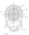
- the laser assembly 8 will now be described in detail with reference to FIGS. 3a and 3b.
- the laser optics 12 has a cylindrical (or cuboid) housing, that for the above-mentioned gimbal in the legs of a U-bracket 30 is rotatably mounted, which in turn is rotatably mounted on its base.
- the laser optics 12 in the eccentricity assembly 32 mounted, which includes a mounting plate 34, on which a gear 36 is rotatable is stored.
- the gear 36 has a center hole through which the laser optics 12 passes.
- the gear 36 is by means of a drive motor 38 and the Drive gear 37 rotatable about its axis.
- the mounting plate 34 On the opposite side the mounting plate 34 is within one with the gear 36th connected outer ring 40 a pendulum sliding bearing 42, whose eccentricity in With respect to the outer ring 40 up to a maximum value of, for example, 10 mm is adjustable.
- the pendulum sliding bearing 42 encloses the housing of Laser Optics 12 fitting and is firmly connected to this.
- the laser assembly 8 further includes a CCD camera with which the workpiece 46 is displayed on a monitor in the area of the processing station.
- the axis of the laser optics 12 circles in the area of the eccentricity module 32 at a distance of a few Millimeters (corresponding to the adjusted eccentricity) about a central axis 48 the laser assembly 8, which is aligned with the head of the ball end mill 6. Since the laser optics 12 at its other end in a gimbal bearing 30th suspended, it performs a precision movement about the central axis 48.
- the laser beam 14 describes at the location of the on the work table 18 workpiece 46 a circular path around the central axis 48th If the just machined surface on the workpiece 46 is flat and parallel to Working table 18 extends, describes the laser focal spot of the laser beam 14 a Ellipse path on the workpiece 46 when the drive motor 38 is driven, the range of motion is limited to about half an ellipse, to prevent the laser beam 14 from being applied to the shaft of the ball end mill 6 can fall.
- the eccentricity of the eccentricity assembly 32 is adjusted so that the mean radius of the circular path the radius of the ball nose cutter plus the Radius of the laser focal spot corresponds, which varies depending on the inclination of the Component gives a certain distance of the focal spot to the chip cross section. This distance should generally be as small as possible, but it will be through limited the head diameter of the ball end mill 6.
- the workpiece 46 moves continuously under the ball end mill 6 away, and the gear 36 is rotated in each case in a position in which the Laser spot 50 drops to a spot on the workpiece 46, which in one the following moment is processed by the ball end mill 6.
- the laser focal spot 50 at the same time accordingly 2 shows the movement path 51 of the Laser burn spot 50 in relation to a feed movement of the ball end mill 6 in the Y direction 60 and X direction 61, wherein the laser focal spot 50th always precedes the processing point by a few millimeters and thereby the entire chip cross section heated.
- the contour milling or the equidistant milling usually changes direction up to 360 °, whereby the milling paths open as closed contours depict the component. Since the compensation of milling direction changes in the As described apparatus is limited to 180 °, such alternatives Milling strategies are tracked only with restrictions.
- the workpiece 46 is pivoted or rotated in the course of processing (order the axes 22 and 24, see Fig. 1) to the angle of the ball cutter 6 to keep the workpiece surface constant.
- the angle of attack only in the feed direction to keep constant.
- a constant angle of attack in two levels can bring about further advantages for the cutting process.
- the circular or elliptical movement of the laser focal spot 50 by means of the drive motor 38 are controlled around the processing point around. This requires, that are interpolated by the machine control 6 axes and the CAD / CAM system the appropriate NC programs at adapted Milling strategy generated.
- the angle of attack can only be kept constant in the feed direction be, where in the processing of free-form surfaces of the chip cross-section moved along the cutting edge of the ball end mill 6. Also in this case, with the device described a tracking of the laser focal spot 50 possible, so that the chip cross section through the laser beam 14 can be heated optimally.
- the one with Multiplication factor ( ⁇ 1) is linked, which in turn is from the angle of inclination the laser optics 12 to the axis of the work spindle 4 and to the normal of the workpiece surface depends.
- the machine control directly calculate how the drive motor 38 is driven must be in order to the laser focal spot 50 always in the right place position.
- a further improvement of the processing options results when the Milling unit is rotatably arranged about the axis of the work spindle (4).
Landscapes
- Engineering & Computer Science (AREA)
- Physics & Mathematics (AREA)
- Optics & Photonics (AREA)
- Mechanical Engineering (AREA)
- Plasma & Fusion (AREA)
- Laser Beam Processing (AREA)
- Milling Processes (AREA)
Description
Claims (8)
- Fräsmaschine mit Laserunterstützung, mitdadurch gekennzeichnet, dass das Fräswerkzeug ein Kugelkopffräser ist und dass die Fräsmaschineeiner Fräseinheit mit einer motorisch angetriebenen Arbeitsspindel (4) zur Aufnahme eines Fräswerkzeuges (6),einem Arbeitstisch (18) zum Aufspannen von Werkstücken,Führungen und Antriebsorgane zur Erzeugung von Relativbewegungen der Fräseinheit und des Arbeitstisches (18) in drei Raumrichtungen, undeiner Lasereinrichtung (12) zum Aussenden eines Laserstrahles (14),Lager (30, 32) und Antriebsorgane (36, 38) zur Erzeugung einer Präzisions-bewegung der Lasereinrichtung (12) um einen Punkt auf der Strahlachse umfasst, wobei der Laserstrahl (14) um eine Mittelachse (48) kreist, welche die Achse der Arbeitsspindel (4) unter einem spitzen Winkel schneidet, undLager und Antriebsorgane zum Drehen und/oder Schwenken des Arbeitstisches (18) um mindestens eine Achse (22, 24) aufweist.
- Fräsmaschine nach Anspruch 1, dadurch gekennzeichnet, dass die Lasereinrichtung (12) an einer Stelle auf der Strahlachse kardanisch (30) gelagert ist und an einer davon beabstandeten Stelle auf der Strahlachse exzentrisch (32) gelagert ist.
- Fräsmaschine nach Anspruch 1 oder 2, dadurch gekennzeichnet, dass die Lager (32) für eine Präzisionsbewegung der Lasereinrichtung (12) dafür eingerichtet sind, die Amplitude der Präzisionsbewegung innerhalb eines vorbestimmten Bereiches einzustellen.
- Fräsmaschine nach einem der vorhergehenden Ansprüche, dadurch gekennzeichnet, dass die Fräseinheit um die Achse der Arbeitsspindel (4) drehbar ist.
- Fräsmaschine nach einem der vorhergehenden Ansprüche, dadurch gekennzeichnet, dass die Lasereinrichtung (12) an einem Fräskopf (2) befestigt ist, in dem die Arbeitsspindel (4) gelagert ist.
- Fräsmaschine nach einem der vorhergehenden Ansprüche, dadurch gekennzeichnet, dass die Lasereinrichtung (12) eine Laseroptik ist, die über einen flexiblen Lichtwellenleiter mit einer getrennten Laserlichtquelle verbunden ist.
- Verfahren zum Fräsen eines Werkstückes mit Laserunterstützung bei dem man das Werkstück und ein rotierendes Fräswerkzeug in drei Raumrichtungen relativ zueinander bewegt,
dadurch gekennzeichnet, dass man als Fräswerkzeug einen Kugelkopffräser (6) verwendet, dass während des Fräsens eine Lasereinrichtung (12) einen Laserstrahl (14) auf eine Stelle der Werkstückoberfläche richtet, die der Fräsbearbeitungsstelle in der aktuellen Vorschubrichtung vorauseilt, dass man die Lasereinrichtung eine Präzisionsbewegung um einen Punkt auf der Strahlachse durchführen lässt, um Änderungen der Fräsrichtung während der Bearbeitung zu kompensieren, und dass man das Werkstück (46) während der Bearbeitung zusätzlich dreht und/oder schwenkt, um den Anstellwinkel des Kugelkopffräsers zur Werkstückoberfläche in mindestens einer Ebene konstant zu halten. - Verfahren nach Anspruch 7, dadurch gekennzeichnet, dass als Frässtrategie Tastfräsen verwendet wird.
Applications Claiming Priority (2)
| Application Number | Priority Date | Filing Date | Title |
|---|---|---|---|
| DE10128536A DE10128536C2 (de) | 2001-06-13 | 2001-06-13 | Fräsmaschine und Fräsverfahren |
| DE10128536 | 2001-06-13 |
Publications (3)
| Publication Number | Publication Date |
|---|---|
| EP1266719A2 EP1266719A2 (de) | 2002-12-18 |
| EP1266719A3 EP1266719A3 (de) | 2003-05-02 |
| EP1266719B1 true EP1266719B1 (de) | 2004-08-11 |
Family
ID=7688068
Family Applications (1)
| Application Number | Title | Priority Date | Filing Date |
|---|---|---|---|
| EP02012215A Expired - Lifetime EP1266719B1 (de) | 2001-06-13 | 2002-06-04 | Fräsmaschine und Fräsverfahren |
Country Status (5)
| Country | Link |
|---|---|
| US (1) | US6666630B2 (de) |
| EP (1) | EP1266719B1 (de) |
| JP (1) | JP2003019615A (de) |
| DE (2) | DE10128536C2 (de) |
| ES (1) | ES2223999T3 (de) |
Cited By (1)
| Publication number | Priority date | Publication date | Assignee | Title |
|---|---|---|---|---|
| DE102004002590A1 (de) * | 2004-01-16 | 2005-08-11 | Daimlerchrysler Ag | Vorrichtung zum Bearbeiten von Werkstücken |
Families Citing this family (72)
| Publication number | Priority date | Publication date | Assignee | Title |
|---|---|---|---|---|
| US7073244B2 (en) * | 2002-09-20 | 2006-07-11 | Lear Corporation | Process for machining a flexible foam |
| ES2239514B1 (es) * | 2003-07-31 | 2007-02-01 | Universidad Del Pais Vasco-Euskal Herriko Unibertsitatea | Procedimiento de fresado asistido por aportacion termica mediante antorcha de plasma y dispositivo de acoplamiento de la antorcha al husillo de la fresadora. |
| DE102004014054B4 (de) * | 2004-03-23 | 2009-09-03 | Daimler Ag | Verfahren zum Ausrichten eines Werkstücks |
| WO2006021404A1 (en) * | 2004-08-23 | 2006-03-02 | Andreas Reinhardt | Method for producing a figurine |
| CN100374243C (zh) * | 2005-01-14 | 2008-03-12 | 财团法人工业技术研究院 | 激光辅助切削装置 |
| DE102005008095A1 (de) * | 2005-02-22 | 2006-08-31 | Geiss Ag | Vorrichtung und Verfahren zum Einbringen von Schwächungslinien in ein an sich steifes Bauteil |
| CA2558898C (en) * | 2005-09-07 | 2013-11-05 | Purdue Research Foundation | Laser assisted machining process with distributed lasers |
| DE102006003682A1 (de) | 2006-01-24 | 2007-07-26 | Jenoptik Automatisierungstechnik Gmbh | Kombinierte Vorrichtung zur Materialbearbeitung mit einem Fräser und einem Laser |
| US8604381B1 (en) * | 2006-10-12 | 2013-12-10 | Purdue Research Foundation | Integrated laser material processing cell |
| CA2614310C (en) * | 2006-12-15 | 2014-05-06 | Quickmill, Inc. | Profile characterization |
| US8847114B1 (en) * | 2007-05-07 | 2014-09-30 | Purdue Research Foundation | Laser-assisted micromachining system and method |
| DE102007032044A1 (de) * | 2007-07-10 | 2009-01-15 | Robert Bosch Gmbh | Werkzeugmaschine |
| IL192785A0 (en) * | 2007-10-22 | 2009-02-11 | Gershon Harif | Cutting tool with protrusions, and methods of use thereof |
| US7736102B2 (en) * | 2008-08-06 | 2010-06-15 | United Technologies Corporation | Control of white-etched layer during machining |
| DE102009008284B4 (de) | 2009-02-10 | 2019-03-14 | Fraunhofer-Gesellschaft zur Förderung der angewandten Forschung e.V. | Verfahren und Vorrichtung zur laserunterstützten, spanenden Bearbeitung von hochfesten Werkstoffen |
| US8839497B2 (en) * | 2009-02-19 | 2014-09-23 | Purdue Research Foundation | Machining apparatus and process |
| KR101184311B1 (ko) | 2009-06-26 | 2012-09-21 | 한국기계연구원 | 예열선삭공정이 적용된 밀링가공장치 |
| JP5364132B2 (ja) * | 2011-08-03 | 2013-12-11 | 富士重工業株式会社 | 切削装置および切削方法 |
| DE102011109810A1 (de) | 2011-08-08 | 2013-02-14 | Institut für innovative Technologien, Technologietransfer, Ausbildung und berufsbegleitende Weiterbildung (ITW) e. V. | Verfahren und Vorrichtung zur laserunterstützten spanenden Bearbeitung von schwer zerspanbaren Werkstoffen |
| CN102430904A (zh) * | 2011-10-19 | 2012-05-02 | 哈尔滨工业大学 | 激光加热辅助铣削加工方法与装置 |
| US9539681B2 (en) | 2011-11-30 | 2017-01-10 | Board Of Trustees Of Northern Illinois University | Laser assisted machining system for ceramics and hard materials |
| EP2855060A2 (de) | 2012-05-24 | 2015-04-08 | Gershon System Ltd. | Verfahren für den entwurf einer schneidkante eines schneidwerkzeugs, schneidwerkzeuge damit und schneidelement mit mehreren solchen teilen |
| JP6029163B2 (ja) * | 2012-06-06 | 2016-11-24 | 浜井産業株式会社 | 歯車加工機 |
| DE112012006740T5 (de) * | 2012-07-27 | 2015-05-21 | Industry-Academic Cooperation Foundation Changwon National University | Laser-Vorwärm-Bearbeitungsvorrichtung |
| BR112015008781B1 (pt) * | 2012-10-19 | 2019-10-08 | Ipg Photonics Corporation | Pistola de solda a laser manobrável à mão e método de solda |
| CN103862085B (zh) * | 2012-12-14 | 2016-05-11 | 倪伟华 | 一种多功能铣床 |
| JP6056564B2 (ja) * | 2013-03-08 | 2017-01-11 | 株式会社Ihi | セラミックマトリックス複合材の加工方法 |
| JP2015047621A (ja) * | 2013-09-02 | 2015-03-16 | 三菱重工業株式会社 | 複合加工装置及び複合加工方法 |
| US9975183B2 (en) | 2013-09-17 | 2018-05-22 | Gershon System Ltd. | Cutting element and a method of cutting using the same |
| CN103741135A (zh) * | 2013-12-19 | 2014-04-23 | 辽宁金之运激光工程技术有限公司 | 一种再制造金属表面的装置及其使用方法 |
| DE102014105505A1 (de) * | 2014-04-17 | 2015-10-22 | Tutech Innovation Gmbh | Verfahren und Vorrichtung zum lasergestützten Trennen eines Werkstücks |
| US9964944B2 (en) | 2014-05-15 | 2018-05-08 | Hurco Companies, Inc. | Material processing unit controlled by rotation |
| CN104227101B (zh) * | 2014-09-16 | 2016-08-24 | 东北大学 | 新型螺旋铣孔装置 |
| US9364931B2 (en) * | 2014-10-09 | 2016-06-14 | Metal Industries Research And Development Centre | Laser-assisted machining device |
| CN105127758A (zh) * | 2015-10-15 | 2015-12-09 | 山东理工大学 | 机床用多轴复合装置 |
| CN105269048A (zh) * | 2015-10-28 | 2016-01-27 | 南昌航空大学 | 一种碳纤维复合材料陀螺式铣削钻孔工艺 |
| CN105382314A (zh) * | 2015-12-11 | 2016-03-09 | 中国南方航空工业(集团)有限公司 | 喷嘴加工方法和装置 |
| US10373449B2 (en) * | 2016-01-19 | 2019-08-06 | The Boeing Company | System and method for protective eyewear |
| KR102148383B1 (ko) * | 2016-01-22 | 2020-08-26 | 주식회사 포스코 | 방향성 전기강판의 자구미세화 방법과 그 장치 |
| KR101653524B1 (ko) * | 2016-07-01 | 2016-09-01 | 이석준 | 레이저 3차원 가공 시스템 |
| CN106273415B (zh) * | 2016-08-19 | 2018-06-01 | 上海三束实业有限公司 | 一种塑料激光焊接机 |
| JP2018034232A (ja) * | 2016-08-30 | 2018-03-08 | ファナック株式会社 | 流体噴射装置 |
| TWI610750B (zh) * | 2016-12-08 | 2018-01-11 | 東台精機股份有限公司 | 複合加工之加工機及其雷射分光裝置 |
| CN106735699B (zh) * | 2016-12-27 | 2019-02-19 | 重庆晶宇光电科技有限公司 | 焊接用多功能旋转台 |
| CN106825837B (zh) * | 2016-12-27 | 2019-02-19 | 重庆晶宇光电科技有限公司 | 基于多功能旋转台的焊接方法 |
| CN107020520B (zh) * | 2017-04-25 | 2019-06-28 | 华中科技大学 | 一种集成温度场实时测量和反馈控制功能的激光预热加工系统 |
| CN108312506A (zh) * | 2017-12-29 | 2018-07-24 | 网云(武汉)三维科技股份有限公司 | 一种粉末粘接3d打印机 |
| US11086296B2 (en) | 2018-01-04 | 2021-08-10 | Hurco Companies, Inc. | Additive manufacturing tool |
| CN108436586B (zh) * | 2018-04-24 | 2019-10-29 | 青岛理工大学 | 一种切削液喷嘴可智能随动的铣床加工系统及工作方法 |
| CN108838689B (zh) * | 2018-06-20 | 2019-08-13 | 华中科技大学 | 一种用于激光辅助铣削中的准直器位姿调节装置及方法 |
| CN108817489B (zh) * | 2018-06-20 | 2019-08-13 | 华中科技大学 | 用于自由曲面激光辅助铣削的准直器位姿调节装置及方法 |
| CN109079349A (zh) * | 2018-09-21 | 2018-12-25 | 杨晓明 | 一种镜片切割装置及镜片切割方法 |
| CN109500604B (zh) * | 2018-12-06 | 2020-08-11 | 哈尔滨工业大学 | 五维手动位移平台、含有五维手动位移平台的车削辅助系统及车削辅助系统的调试方法 |
| CN110695707A (zh) * | 2019-11-11 | 2020-01-17 | 机械科学研究总院海西(福建)分院有限公司 | 一种龙门铣激光自动焊接复合机床 |
| CN111769008B (zh) * | 2020-07-20 | 2022-08-05 | 昆山联滔电子有限公司 | 一种接线柱加工装置及加工方法 |
| CN114160848A (zh) * | 2020-09-11 | 2022-03-11 | 汉达精密电子(昆山)有限公司 | 一种铣切一体化装置 |
| CN112192020B (zh) * | 2020-09-28 | 2022-09-09 | 哈尔滨理工大学 | 一种加工球头铣刀跨尺度微特征的夹具 |
| CN113333840A (zh) * | 2021-05-31 | 2021-09-03 | 西北工业大学 | 一种热辅助铣削装置 |
| CN113664263B (zh) * | 2021-09-24 | 2025-06-06 | 上海振华重工(集团)股份有限公司 | 一种大型回转面自调水平加工设备 |
| CN113885435B (zh) * | 2021-10-21 | 2023-11-28 | 华中科技大学 | 激光调整与路径补偿结合的激光辅助曲面加工方法及装置 |
| CN114178594B (zh) * | 2021-12-10 | 2022-12-23 | 上海交通大学 | 含偏差筒形薄壁铸件内腔铣削加工系统及加工方法 |
| CN114178861A (zh) * | 2021-12-15 | 2022-03-15 | 山西其明科技发展有限公司 | 一种机电自动化加工用球型材料切磨一体成型设备 |
| CN114425701B (zh) * | 2021-12-22 | 2023-10-24 | 哈尔滨理工大学 | 一种推动式偏心偏角加工调整装置 |
| CN114713868A (zh) * | 2022-03-22 | 2022-07-08 | 天津大学 | 一种应用于激光辅助车削加工的一体化刀具 |
| CN114850876B (zh) * | 2022-04-08 | 2024-06-18 | 大连理工大学 | 一种激光辅助铣磨加工装置及方法 |
| CN114770234B (zh) * | 2022-04-08 | 2023-10-20 | 大连理工大学 | 一种激光复合超声辅助磨削机床及加工方法 |
| CN115415666B (zh) * | 2022-09-07 | 2024-08-16 | 哈尔滨理工大学 | 一种铍材专用的激光辅助刻划和粉末回收装置 |
| CN115592423B (zh) * | 2022-12-01 | 2023-03-10 | 太原理工大学 | 一种激光辅助钻削的加工装置 |
| CN116100685A (zh) * | 2022-12-30 | 2023-05-12 | 杭州大和江东新材料科技有限公司 | 一种复合式碳化硅陶瓷加工装置及其工作方法 |
| CN116921747A (zh) * | 2023-06-13 | 2023-10-24 | 苏州鑫荣健身器材有限公司 | 一种按摩器钣金铣加工装置 |
| CN116728001B (zh) * | 2023-08-16 | 2023-11-03 | 西南交通大学 | 一种晶粒梯度细化的高完整性金属材料表面加工方法 |
| CN120228418B (zh) * | 2025-05-30 | 2025-10-17 | 浙江摩克激光智能装备有限公司 | 一种用于激光振镜加工的金刚石刀具自动定位方法 |
Family Cites Families (29)
| Publication number | Priority date | Publication date | Assignee | Title |
|---|---|---|---|---|
| USRE25105E (en) * | 1961-12-26 | figure | ||
| US2654821A (en) * | 1948-07-15 | 1953-10-06 | Warner Swasey Co | Hot machining of metals |
| BE493761A (fr) * | 1949-02-08 | 1950-06-01 | Procédé et appareillage pour régler la chaleur utilisée dans les procédes d'usinage a chaud | |
| US4733049A (en) * | 1963-01-11 | 1988-03-22 | Lemelson Jerome H | Machining method and apparatus |
| JPS5469896A (en) * | 1977-11-15 | 1979-06-05 | Koyo Seiko Co Ltd | Method of machining work outer surface with laser beam |
| IT1106970B (it) * | 1978-01-18 | 1985-11-18 | Istituto Per Le Ricerche Di Te | Procedimento per la lavorazione ad asportazione di truciolo con l'impiego del raggio laser ed apparecchio per l'esecuzione del procedimento |
| DE3005429C2 (de) * | 1979-02-23 | 1984-09-06 | Crosfield Electronics Ltd., London | Lasergraviermaschine |
| US4356376A (en) * | 1981-05-13 | 1982-10-26 | General Electric Company | Pulse laser pretreated machining |
| US4459458A (en) * | 1982-08-30 | 1984-07-10 | The Warner & Swasey Company | Machine tool with laser heat treating |
| DE3404869A1 (de) * | 1984-02-11 | 1985-08-14 | Heyligenstaedt & Co, Werkzeugmaschinenfabrik Gmbh, 6300 Giessen | Portalfraesmaschine |
| JPS61152345A (ja) * | 1984-12-24 | 1986-07-11 | Toshiba Corp | レ−ザ併用加工法 |
| JPH0753853Y2 (ja) * | 1988-07-11 | 1995-12-13 | 三菱マテリアル株式会社 | ボールエンドミル |
| EP0369057B1 (de) * | 1988-11-18 | 1994-06-15 | Toyoda Koki Kabushiki Kaisha | Verfahren und Vorrichtung zur Behandlung einer bearbeiteten Fläche eines Werkstücks |
| FR2662383B1 (fr) * | 1990-05-28 | 1994-12-23 | Snecma | Dispositif d'amenee d'un faisceau laser a une piece a usiner. |
| BE1004441A6 (fr) * | 1990-06-06 | 1992-11-24 | Baikrich Michel | Appareil de pointage a faisceau laser. |
| JPH0543997Y2 (de) * | 1990-09-10 | 1993-11-08 | ||
| DE4113633C2 (de) * | 1991-04-26 | 1994-06-30 | Manfred Toeller | Bearbeitungsvorrichtung |
| JPH05104366A (ja) * | 1991-10-17 | 1993-04-27 | Fanuc Ltd | 複合工作機械 |
| US5409376A (en) * | 1993-03-10 | 1995-04-25 | Murphy; Quentin M. | Apparatus and process for laser-assisted driling |
| JPH071293A (ja) * | 1993-06-14 | 1995-01-06 | Nippon Autom Kk | 加工機械用位置合わせ装置 |
| CH689643A5 (fr) * | 1994-02-18 | 1999-07-30 | Speno International | Installation pour le reprofilage des rails d'une voie ferrée. |
| US6122824A (en) * | 1995-11-01 | 2000-09-26 | Jensen; David L. | Method for manufacturing fluid compression/compressor rotor |
| DE19613183C1 (de) * | 1996-04-02 | 1997-07-10 | Daimler Benz Ag | Verfahren und Vorrichtung zum Feindrehen eines Werkstückes aus einem härtbaren Stahl mittels Drehmeißel |
| FR2750067B1 (fr) * | 1996-06-20 | 1998-07-31 | Snecma | Procede de fraisage assiste par laser |
| CA2259700C (en) * | 1998-01-21 | 2007-05-08 | Clive G. Whittenbury | Laser-assisted cutting device |
| DE19910880A1 (de) * | 1999-03-11 | 2000-09-14 | Deckel Maho Gmbh | Werkzeugmaschine für die Werkstückbearbeitung mit spanenden Werkzeugen und Laserstrahl |
| JP2001150256A (ja) * | 1999-11-29 | 2001-06-05 | Olympus Optical Co Ltd | ワークの複合加工方法 |
| JP2001239795A (ja) * | 2000-02-28 | 2001-09-04 | Ando Electric Co Ltd | 打刻方法及びその装置 |
| DE10012647B4 (de) * | 2000-03-15 | 2009-09-24 | Reishauer Ag | Einrichtverfahren für ein Bearbeitungswerkzeug bzw. Werkstück auf einer Verzahnungsmaschine |
-
2001
- 2001-06-13 DE DE10128536A patent/DE10128536C2/de not_active Expired - Fee Related
-
2002
- 2002-06-04 EP EP02012215A patent/EP1266719B1/de not_active Expired - Lifetime
- 2002-06-04 DE DE50200786T patent/DE50200786D1/de not_active Expired - Fee Related
- 2002-06-04 ES ES02012215T patent/ES2223999T3/es not_active Expired - Lifetime
- 2002-06-10 JP JP2002169085A patent/JP2003019615A/ja active Pending
- 2002-06-13 US US10/171,111 patent/US6666630B2/en not_active Expired - Fee Related
Cited By (1)
| Publication number | Priority date | Publication date | Assignee | Title |
|---|---|---|---|---|
| DE102004002590A1 (de) * | 2004-01-16 | 2005-08-11 | Daimlerchrysler Ag | Vorrichtung zum Bearbeiten von Werkstücken |
Also Published As
| Publication number | Publication date |
|---|---|
| US6666630B2 (en) | 2003-12-23 |
| US20030059268A1 (en) | 2003-03-27 |
| DE10128536A1 (de) | 2003-01-02 |
| EP1266719A3 (de) | 2003-05-02 |
| EP1266719A2 (de) | 2002-12-18 |
| DE10128536C2 (de) | 2003-06-26 |
| JP2003019615A (ja) | 2003-01-21 |
| DE50200786D1 (de) | 2004-09-16 |
| ES2223999T3 (es) | 2005-03-01 |
Similar Documents
| Publication | Publication Date | Title |
|---|---|---|
| DE10128536C2 (de) | Fräsmaschine und Fräsverfahren | |
| DE102005021640B4 (de) | Maschine zur Bearbeitung von optischen Werkstücken, insbesondere von Kunststoff-Brillengläsern | |
| DE60203154T2 (de) | Vorrichtung zur Bearbeitung von Brillengläsern | |
| EP0685298B2 (de) | Verfahren und Vorrichtung zum Herstellen asphärischer Linsenoberflächen | |
| DE10143848C2 (de) | Verfahren und Vorrichtung zur Flächenbearbeitung von Werkstücken aus nicht-sprödharten Materialien in der Optikfertigung sowie Werkzeug dafür | |
| DE60304646T2 (de) | Mehrzweckwerkzeugmaschine und Bearbeitungsverfahren in einer Mehrzweckwerkzeugmaschine | |
| DE19529786C1 (de) | Verfahren und Werkzeug zur Erzeugung einer konkaven Oberfläche an einem Brillenglasrohling | |
| DE19616526A1 (de) | Maschine zur materialabtragenden Bearbeitung optischer Werkstoffe für die Herstellung von Optikteilen | |
| DE10256222B4 (de) | Maschine und Verfahren mit 7 Achsen zum CNC-gesteuerten spanabhebenden Bearbeiten, insbesondere Wälzfräsen oder Wälzschleifen, von Spiralkegelrädern | |
| EP1422005B1 (de) | Verfahren und Vorrichtung zur Randbearbeitung einer optischen Linse aus Kunststoff | |
| EP0262225A1 (de) | Laserbehandungsanlage | |
| DE3404838A1 (de) | Bohr- und fraeswerk | |
| EP3124175B1 (de) | Verfahren zur bearbeitung von optischen werkstücken, insbesondere brillenlinsen aus kunststoff | |
| DE3932197A1 (de) | Schleif- und nachbearbeitungseinrichtung sowie verfahren zum schleifen und nachbehandeln | |
| EP0936028B1 (de) | Vorrichtung zum Superfinishen bearbeiteter Oberflächen | |
| DE4222967A1 (de) | Vorrichtung und Steuerung zum Erzeugen von Unrund-/Ballig-Geometrien an Drehteilen | |
| EP1392464B1 (de) | Schleifmaschine zum beidseitigen schleifen von sägezahnflanken | |
| DE3520521C2 (de) | ||
| DE102005020485B3 (de) | Bündigfräs- und Abziehaggregat | |
| DE19616525A1 (de) | Werkzeug zur materialabtragenden Bearbeitung optischer Werkstoffe | |
| DE623090C (de) | Vorschubvorrichtung fuer Holzbearbeitungsmaschinen | |
| DE102004058962B4 (de) | Werkzeug | |
| DE3913294A1 (de) | Vorrichtung zum fraesen von unrundprofilen | |
| DE19630426A1 (de) | Vorrichtung und Verfahren zum CNC-gesteuerten Herstellen von Leisten | |
| DE19737215A1 (de) | Werkzeugkomibation bestehend aus Spannwerkzeug für Linsen und Abrichtwerkzeug für Polierwerkzeuge |
Legal Events
| Date | Code | Title | Description |
|---|---|---|---|
| PUAI | Public reference made under article 153(3) epc to a published international application that has entered the european phase |
Free format text: ORIGINAL CODE: 0009012 |
|
| AK | Designated contracting states |
Kind code of ref document: A2 Designated state(s): AT BE CH CY DE DK ES FI FR GB GR IE IT LI LU MC NL PT SE TR |
|
| AX | Request for extension of the european patent |
Free format text: AL;LT;LV;MK;RO;SI |
|
| PUAL | Search report despatched |
Free format text: ORIGINAL CODE: 0009013 |
|
| AK | Designated contracting states |
Designated state(s): AT BE CH CY DE DK ES FI FR GB GR IE IT LI LU MC NL PT SE TR |
|
| AX | Request for extension of the european patent |
Extension state: AL LT LV MK RO SI |
|
| 17P | Request for examination filed |
Effective date: 20030528 |
|
| GRAP | Despatch of communication of intention to grant a patent |
Free format text: ORIGINAL CODE: EPIDOSNIGR1 |
|
| AKX | Designation fees paid |
Designated state(s): DE ES IT |
|
| GRAS | Grant fee paid |
Free format text: ORIGINAL CODE: EPIDOSNIGR3 |
|
| RBV | Designated contracting states (corrected) |
Designated state(s): DE ES FR IT |
|
| GRAA | (expected) grant |
Free format text: ORIGINAL CODE: 0009210 |
|
| AK | Designated contracting states |
Kind code of ref document: B1 Designated state(s): DE ES FR IT |
|
| REG | Reference to a national code |
Ref country code: IE Ref legal event code: FG4D Free format text: GERMAN |
|
| REF | Corresponds to: |
Ref document number: 50200786 Country of ref document: DE Date of ref document: 20040916 Kind code of ref document: P |
|
| REG | Reference to a national code |
Ref country code: ES Ref legal event code: FG2A Ref document number: 2223999 Country of ref document: ES Kind code of ref document: T3 |
|
| REG | Reference to a national code |
Ref country code: IE Ref legal event code: FD4D |
|
| ET | Fr: translation filed | ||
| PG25 | Lapsed in a contracting state [announced via postgrant information from national office to epo] |
Ref country code: IT Free format text: LAPSE BECAUSE OF NON-PAYMENT OF DUE FEES Effective date: 20050604 |
|
| PG25 | Lapsed in a contracting state [announced via postgrant information from national office to epo] |
Ref country code: ES Free format text: LAPSE BECAUSE OF NON-PAYMENT OF DUE FEES Effective date: 20050606 |
|
| PLBE | No opposition filed within time limit |
Free format text: ORIGINAL CODE: 0009261 |
|
| STAA | Information on the status of an ep patent application or granted ep patent |
Free format text: STATUS: NO OPPOSITION FILED WITHIN TIME LIMIT |
|
| 26N | No opposition filed |
Effective date: 20050512 |
|
| PG25 | Lapsed in a contracting state [announced via postgrant information from national office to epo] |
Ref country code: DE Free format text: LAPSE BECAUSE OF NON-PAYMENT OF DUE FEES Effective date: 20060103 |
|
| PG25 | Lapsed in a contracting state [announced via postgrant information from national office to epo] |
Ref country code: FR Free format text: LAPSE BECAUSE OF NON-PAYMENT OF DUE FEES Effective date: 20060228 |
|
| REG | Reference to a national code |
Ref country code: FR Ref legal event code: ST Effective date: 20060228 |
|
| REG | Reference to a national code |
Ref country code: ES Ref legal event code: FD2A Effective date: 20050606 |