EP1263151B1 - Adaptive Antennenempfangsanordnung - Google Patents
Adaptive Antennenempfangsanordnung Download PDFInfo
- Publication number
- EP1263151B1 EP1263151B1 EP02011862A EP02011862A EP1263151B1 EP 1263151 B1 EP1263151 B1 EP 1263151B1 EP 02011862 A EP02011862 A EP 02011862A EP 02011862 A EP02011862 A EP 02011862A EP 1263151 B1 EP1263151 B1 EP 1263151B1
- Authority
- EP
- European Patent Office
- Prior art keywords
- antenna
- sections
- null
- initial
- signal
- Prior art date
- Legal status (The legal status is an assumption and is not a legal conclusion. Google has not performed a legal analysis and makes no representation as to the accuracy of the status listed.)
- Expired - Lifetime
Links
- 230000003044 adaptive effect Effects 0.000 title claims description 93
- 230000015572 biosynthetic process Effects 0.000 claims description 117
- 238000003786 synthesis reaction Methods 0.000 claims description 87
- 238000004519 manufacturing process Methods 0.000 claims description 51
- 238000004260 weight control Methods 0.000 claims description 21
- 230000002194 synthesizing effect Effects 0.000 claims description 11
- 238000005259 measurement Methods 0.000 claims description 4
- 238000010586 diagram Methods 0.000 description 11
- 239000013598 vector Substances 0.000 description 8
- 238000004891 communication Methods 0.000 description 5
- 238000000034 method Methods 0.000 description 4
- 230000001427 coherent effect Effects 0.000 description 2
- 230000005540 biological transmission Effects 0.000 description 1
- 230000021615 conjugation Effects 0.000 description 1
Images


Classifications
-
- H—ELECTRICITY
- H04—ELECTRIC COMMUNICATION TECHNIQUE
- H04B—TRANSMISSION
- H04B7/00—Radio transmission systems, i.e. using radiation field
- H04B7/02—Diversity systems; Multi-antenna system, i.e. transmission or reception using multiple antennas
- H04B7/04—Diversity systems; Multi-antenna system, i.e. transmission or reception using multiple antennas using two or more spaced independent antennas
- H04B7/08—Diversity systems; Multi-antenna system, i.e. transmission or reception using multiple antennas using two or more spaced independent antennas at the receiving station
- H04B7/0837—Diversity systems; Multi-antenna system, i.e. transmission or reception using multiple antennas using two or more spaced independent antennas at the receiving station using pre-detection combining
- H04B7/0842—Weighted combining
- H04B7/086—Weighted combining using weights depending on external parameters, e.g. direction of arrival [DOA], predetermined weights or beamforming
-
- H—ELECTRICITY
- H04—ELECTRIC COMMUNICATION TECHNIQUE
- H04B—TRANSMISSION
- H04B7/00—Radio transmission systems, i.e. using radiation field
- H04B7/02—Diversity systems; Multi-antenna system, i.e. transmission or reception using multiple antennas
- H04B7/04—Diversity systems; Multi-antenna system, i.e. transmission or reception using multiple antennas using two or more spaced independent antennas
- H04B7/08—Diversity systems; Multi-antenna system, i.e. transmission or reception using multiple antennas using two or more spaced independent antennas at the receiving station
Definitions
- the present invention relates to a CDMA (Code Division Multiple Access) adaptive antenna reception apparatus, and more particularly to a CDMA adaptive antenna reception apparatus wherein the initial convergence of the antenna weight is completed at a high speed.
- CDMA Code Division Multiple Access
- a conventional CDMA adaptive antenna reception apparatus is disclosed, for example, inN. Nakaminami, T. Ihara, S. Tanaka and M. Sawahashi, "Performance of Coherent Adaptive Antenna Array Diversity Receiver Using the Common Antenna Weights for Rake Combined Paths for W-CDMA Reverse Link", Technical Report RCS2000-46 of the Society for the Study of the Radio Communications System, the Institute of Electronics, Information and Communication Engineers, June, 2000 or S. Tanaka, Y. Miki and M.
- the conventional CDMA adaptive antenna reception apparatus performs weighted synthesis of signals received by a plurality of antennae by adaptive control to form an optimum beampattern which has a high directivity in an incoming direction of a desired signal and has the null of a low directivity in an incoming direction of an interference signal.
- the direction in which the beam pattern has a high directivity is hereinafter referred to as beam direction whereas the direction in which the beam pattern has a low directivity is hereinafter referred to as null direction.
- the conventional CDMA adaptive antenna reception apparatus removes interference from a reception signal and thereby achieves an optimum reception characteristic.
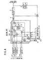
- FIG. 5 is a block diagram showing a configuration of a conventional CDMA adaptive antenna reception apparatus.
- the conventional CDMA adaptive antenna reception apparatus includes K (K is an integer equal to or greater than 2) antennae 1-1 to 1-K and a number of adaptive antenna reception sections 102-1 to 102-N equal the number N (N is an integer equal to or greater than 1) of users.
- the K antennae 1-1 to 1-K are disposed closely to one another so that they may have a high correlation to one another.
- a signal from a certain user is received by the antennae 1-1 to 1-K with phase differences caused by path differences which rely upon a relationship between incoming directions of the signal and the antenna arrangement.
- the antennae 1-1 to 1-K receive signals synthesized from signals from a plurality of users and interference signals such as multi-path interference signals and output the received signals to the adaptive antenna reception sections 102-1 to 102-N.
- the adaptive antenna reception sections 102-1 to 102-N all have a same configuration and are allocated to the N users, that is, the first to Nthusers.
- the CDMA adaptive antenna reception apparatus is capable of processing signals from N users simultaneously.
- the adaptive antenna reception sections 102-1 to 102-N process the reception signals from the users and individually output discrimination results thereof.
- FIG. 6 is a block diagram showing a configuration of an adaptive antenna reception section 102-n (1 ⁇ n ⁇ N, n is an integer) of the conventional adaptive antenna reception apparatus. It is to be noted that the number of multi-paths is L (L is an integer equal to or greater than 1).
- the adaptive antenna reception section 102-n includes K despreading sections 4-1 to 4-K, L antenna weighting synthesis sections 5-1 to 5-L, an adder 6, K adders 9-1 to 9-K, a further adder 11, a discrimination section 7, a reference signal production section 8 and an antenna weight control section 110.
- the antenna weighting synthesis section 5-1 includes K multipliers 5-1-1-1 to 5-1-1-K, a multiplier 5-1-4, K multipliers 5-1-5-1 to 5-1-5-K, an adder 5-1-2 and a channel estimation section 5-1-3. All of the other antenna weighting synthesis sections 5-2 to 5-L have a configuration similar to that of the antenna weighting synthesis section 5-1.
- the K despreading sections 4-1 to 4-K are connected to the K antennae 1-1 to 1-K, respectively.
- the despreading sections 4-1 to 4-K despread signals from the antennae 1-1 to 1-K, respectively, with a spread code allocated to the nth user to separate first path signals and output the first path signals to the L antenna weighting synthesis sections 5-1 to 5-L.
- the first path signals individually separated by the despreading sections 4-1 to 4-K are inputted to all of the antenna weighting synthesis sections 5-1 to 5-L.
- the K multipliers 5-1-1-1 to 5-1-1-K multiply the outputs of the K despreading sections 4-1 to 4-K by antenna weights outputted from the antenna weight control section 110.
- the adder 5-1-2 adds outputs of the multipliers 5-1-1-1 to 5-1-1-K.
- the channel estimation section 5-1-3 estimates a channel distortion from an output of the adder 5-1-2 and outputs a complex conjugate of the channel distortion to the multiplier 5-1-4 and the multipliers 5-1-5-1 to 5-1-5-K.
- the multiplier 5-1-4 multiplies the output of the adder 5-1-2 and the output of the channel estimation section 5-1-3 and outputs a result of the multiplication as a demodulation signal of the first path.
- the K multipliers 5-1-5-1 to 5-1-5-K are connected to the K despreading sections 4-1 to 4-K, respectively.
- the multipliers 5-1-5-1 to 5-1-5-K multiply the outputs of the despreading sections 4-1 to 4-K by the complex conjugate of the channel distortion outputted from the channel estimation section 5-1-3.
- the antenna weighting synthesis sections 5-2 to 5-L output demodulation signals of the second to Lth paths, respectively, similarly to the antenna weighting synthesis section 5-1.
- the adder 6 adds the demodulation signals of the first to Lth paths outputted from the L antenna weighting synthesis sections 5-1 to 5-L to perform RAKE synthesis.
- the discrimination section 7 performs data discrimination of the signal obtained by the RAKE synthesis of the adder 6 and outputs a result of the discrimination.
- the reference signal production section 8 produces a reference signal using the result of the discrimination outputted from the discrimination section 7.
- the adder 11 determines an error signal between the signal obtained by the RAKE synthesis of the adder 6 and the reference signal produced by the reference signal production section 8 and outputs the error signal to the antenna weight control section 110.
- the K adders 9-1 to 9-K correspond to the K antennae 1-1 to 1-K, respectively.
- the adder 9-1 synthesizes the first to Lth path signals separated by the despreading section 4-1 and multiplied by complex conjugates of channel distortions by the antenna weighting synthesis sections 5-1 to 5-L and outputs a despread and path synthesis signal to the antenna weight control section 110.
- the adders 9-2 to 9-K synthesize first to Lth path signals separated by the corresponding despreading sections 4-2 to 4-K and multiplied by complex conjugates of channel distortions by the antenna weighting synthesis sections 5-1 to 5-L and output despread and path synthesis signals to the antenna weight control section 110.
- the antenna weight control section 110 determines antenna weights controlled to minimize the error signal determined by the adder 11 from the error signal and the despread and path synthesis signals obtained by the adders 9-1 to 9-K and outputs the antenna weights to the antenna weighting synthesis sections 5-1 to 5-L.
- the LMS (Least-Mean-Square) algorithm is available.
- the antenna weight of the antenna k (2 ⁇ k ⁇ K, k is an integer) at time t is represented by Wk(t)
- the error signal of the output of the adder 11 is represented by e(t)
- the path synthesis signal of the kth antenna which is an output of the adder 9-K is represented by xk(t)
- ⁇ is a constant called step size
- * represents a complex conjugate. While, in the conventional example described here, an antenna weight common to all of the first to Lth paths is used, antenna weights different among different paths may be produced and used.
- the conventional CDMA adaptive antenna reception apparatus shown in FIGS. 5 and 6 receives, at the K antennae 1-1 to 1-K, signals synthesized from signals from a plurality of users and interference signals with the signals from the users such as multi-path interference signals. Then, the CDMA adaptive antenna reception apparatus despread, at the despreading sections 4-1 to 4-K thereof, the signals received by the antennae 1-1 to 1-K using spread codes individually allocated to the adaptive antenna reception sections 102-1 to 102-N.
- the CDMA adaptive antenna reception apparatus performs, at the L antenna weighting synthesis sections 5-1 to 5-L thereof, weighted synthesis of the signals obtained by despreading of the despreading sections 4-1 to 4-K with weights determined for the individual channels and further performs compensation of the synthesized signals for channel distortions.
- the CDMA adaptive antenna reception apparatus performs the weighting with antenna weights controlled by the antenna weight control section 110.
- the CDMA adaptive antenna reception apparatus RAKE synthesizes, at the adder 6 thereof, the signals synthesized and compensated for by the antenna weighting synthesis sections 5-1 to 5-L, performs, at the discrimination section 7 thereof, data discrimination of the signal obtained by the RAKE synthesis and outputs a result of the discrimination.
- initial values for antenna weights of a conventional CDMA adaptive antenna reception apparatus are usually set to values with which beam patterns become non-directive. Therefore, much time is required until an antenna weight converges from its initial value to a value with which a beam pattern of an optimum solution wherein the directivity is directed to the direction of a desired signal and the null is directed to the direction of an interference signal is formed.
- WO 01/29989A discloses an adaptive antenna reception apparatus according to the preamble of claim 1.
- EP-A-1 093 241 describes an adaptive transceiver device which estimates a path derival direction of a desired wave signal by using a reception antenna weight of a k-user adaptive reception unit using a control method based on the minimum mean square error standards and which generates a transmission antenna weight on the basis of the path arrival direction.
- an adaptive antenna reception apparatus wherein an incoming signal is received by a plurality of antennae and the signals received by the antennae are weighted synthesized with antenna weights to detect a desired signal, comprising one or more adaptive antenna reception sections for adaptively controlling the antenna weights and for multiplying the signals received by the antennae by the antenna weights and synthesizing resulting signals of the multiplication to detect the desired signal, and an initial antenna weight production section for producing one or more initial antenna weight candidates which are candidates for an initial value to be used for the adaptive control of the antenna weights to detect a new desired signal based on antenna weights of desired signals being received which are adaptively controlled by the adaptive antenna reception section.
- the adaptive control of the new desired signal can be started with the antenna weight near to a final solution and therefore converges to the final solution in a short time.
- the adaptive antenna reception apparatus is configured such that the initial antenna weight production section includes one or more beam-null direction search sections provided corresponding to the adaptive antenna reception sections for calculating beam directions and null directions of beam patterns formed with the antenna weights adaptively controlled by the adaptive antenna reception sections, a null formation direction discrimination section for discriminating a desired null direction of a beam pattern by the antenna weight for detecting the new desired signal from the beam directions and the null directions calculated by the beam-null direction search section, and an initial antenna weight candidate production section for producing the one or more initial antenna weight candidates with which beam patterns which have the null in the desired null direction obtained by the null formation direction discrimination section and have different beam directions from each other are formed, and each of the adaptive antenna reception sections starts, when the adaptive antenna reception section is allocated to the new desired signal, the adaptive control of the antenna weight using the initial antenna weight candidate whose beam direction is the incoming direction of the desired signal as an initial value.
- the beam-null direction search sections calculate beam directions and null directions of the antenna weights of the desired signals being received, and the null formation direction discrimination section discriminates a desired null direction of the antenna weight of the new desired signal from the beam directions and the null directions.
- the initial antenna weight candidate production section produces a plurality of initial antenna weight candidates modified so that the null may be formed in the desired null direction, and one of the adaptive antenna reception sections which is allocated to the new desired signal selects and uses the initial antenna weight candidate which forms the beam direction in the incoming direction of the new desired signal. Therefore, the adaptive control of the new desired signal can be started with the antenna weight whose beam direction and null direction are near to those of a final solution and therefore converges to the final solution in a short time.
- the initial antenna weight candidate production section may store one or more prototypes for the antenna weight whose beam directions are different from each other and modify the null directions of the prototypes to the desired null direction obtained by the null formation direction discrimination section to produce the initial antenna weight candidates.
- the null formation direction discrimination section may select, from among the null directions calculated by the beam-null direction search sections, a predetermined number of those ones with regard to which a value obtained by dividing the number of those null directions which are within a predetermined range of the null direction by the number of those ones of the beam-null direction search sections which have calculated those beam patterns whose beam directions are not within the predetermined range of the null direction has a comparatively high value to discriminate the desired null directions of the beam pattern by the antenna weight for detecting the new desired signal.
- adaptive control for detecting a new desired signal is started using an antenna weight or weights of an initial antenna weight candidate or candidates with which a direction in which the null is comparatively likely to be formed is determined as the null direction as an initial value or values. Therefore, the adaptive control of the new desired signal can be started with the antenna weight whose beam direction and null direction are near to those of a final solution and therefore converges to the final solution in a short time.
- the null formation direction discrimination section may select, from among the beam directions calculated by the beam-null direction search sections, a predetermined number of those ones with regard to which a value obtained by dividing the number of those null directions which are within a predetermined range of the beam direction by the number of those ones of the beam-null direction search sections which have calculated those beam patterns whose beam directions are not within the predetermined range of the beam direction has a comparatively high value to discriminate the desired null directions of the beam pattern by the antenna weight for detecting the new desired signal.
- Each of the adaptive antenna reception sections may include a plurality of despreading sections corresponding to the antennae each operable for despreading one of the received signals from the antennae to separate the received signal for multi-paths and outputting a plurality of path signals, one or more first antenna weighting synthesis sections corresponding to the paths each operable for weighted synthesizing the path signals from the despreading sections with the antenna weights, performing channel estimation and compensating for a channel distortion of an antenna weighted synthesis signal and a corresponding one of the path signals, a first adder for adding the antenna weighted synthesis signals of the different paths whose channel distortions have been compensated for to RAKE synthesize the antenna weighted synthesis signals, a discrimination section for discriminating reception data from a signal obtained by the first adder, a reference signal production section for producing a reference signal from a result of the discrimination of the discrimination section, a second adder for producing an error signal which is a difference between the signal obtained by the first adder and the reference
- Each of the first antenna weighting synthesis sections includes a plurality of first multipliers corresponding to the antennae for multiplying pass signals of a predetermined path from all of the despreading sections and the antenna weights for the path from the antenna weight control section individually for the antennae, a fourth adder for adding outputs of the first multipliers to produce the antenna weighted synthesis signal, a first channel estimation section for estimating the channel distortion from the antenna weighted synthesis signal and determining a complex conjugate of the channel distortion, a second multiplier for multiplying the antenna weighted synthesis signal and the complex conjugate of the channel distortion, and a plurality of third multipliers corresponding to the antennae for multiplying the path signals and the complex conjugate of the channel distortion individually for the antennae.
- the initial antenna weight selection section may include a plurality of initial antenna weight discrimination information production sections corresponding to the initial antenna weight candidates for receiving all of the path signals from all of the despreading sections as inputs thereto, weighted synthesizing the path signals with the initial antenna weight candidates produced by the initial antenna weight production section for the individual paths, RAKE synthesizing the weighted synthesized signals for the individual paths and measuring signal to interference power ratios of the new desired signal as discrimination information, and an initial antenna weight discrimination section for selecting optimum ones of the initial antenna weight candidates based on the discrimination information.
- Each of the initial antenna weight discrimination information production sections may include one or more second antenna weighting synthesizing sections corresponding to the paths for weighted synthesizing the path signals with the initial antenna weight candidates, a fifth adder for adding signals obtained by the weighted synthesis of the second antenna weighting synthesis sections to RAKE synthesize the signals, and a signal to interference power ratio measurement section for measuring a signal to interference power ratio of a signal obtained by the fifth adder.
- Each of the second antenna weighting synthesis sections may include a plurality of fourth multipliers corresponding to the antennae for multiplying path signals of a predetermined path from all of the despreading sections and the initial antenna weight candidates for the path individually for the antennae, a sixth adder for adding outputs of the fourth multipliers, a second channel estimation section for estimating a channel distortion from a signal obtained by the sixth adder and determining a complex conjugate of the channel distortion, and a fifth multiplier for multiplying the signal obtained by the sixth adder and the complex conjugate of the channel distortion.
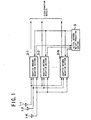
- FIG. 1 there is shown a configuration of a CDMA adaptive antenna reception apparatus to which the present invention is applied.
- the CDMA adaptive antenna reception apparatus includes K (K is an integer equal to or greater than 2) antennae 1-1 to 1-K, a number of adaptive antenna reception sections 2-1 to 2-N equal to the number N (N is an integer equal to or greater than 1) of users, and an initial antenna weight production section 3.
- the K antennae 1-1 to 1-K are disposed closely to one another so that they may have a high correlation to one another.
- a signal from a certain user is received by the antennae 1-1 to 1-K with phase differences caused by path differences which rely upon the incoming directions of the signal and the antenna arrangement.
- the antennae 1-1 to 1-K receive signals synthesized from signals from a plurality of users and interference signals with the signals from the users such as multi-path interference signals and output the received signals to the N adaptive antenna reception sections 2-1 to 2-N.
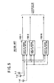
- FIG. 2 is a block diagram showing a configuration of the nth adaptive antenna reception section 2-n (1 ⁇ n ⁇ N, n is an integer) of the adaptive antenna reception apparatus of FIG. 1 . It is to be noted that the number of multi-paths is L (L is an integer equal to or greater than 1).
- the adaptive antenna reception section 2-n includes K despreading sections 4-1 to 4-K, L antenna weighting synthesis sections 5-1 to 5-L, an adder 6, K adders 9-1 to 9-K, a further adder 11, a discrimination section 7, a reference signal production section 8, an antenna weight control section 10 and an initial antenna weight selection section 12.
- the antenna weighting synthesis section 5-1 includes K multipliers 5-1-1-1 to 5-1-1-K, another multiplier 5-1-4, K multipliers 5-1-5-1 to 5-1-5-K, an adder 5-1-2 and a channel estimation section 5-1-3.
- the antenna weighting synthesis sections 5-2 to 5-L all have a configuration similar to that of the antenna weighting synthesis section 5-1.
- the K despreading sections 4-1 to 4-K are connected to the K antennae 1-1 to 1-K, respectively.
- the despreading sections 4-1 to 4-K despread signals from the antennae 1-1 to 1-K with a spread code allocated to an nth user to separate first path signals and output the first path signals to the L antenna weighting synthesis sections 5-1 to 5-L.
- the first path signals individually separated by the despreading sections 4-1 to 4-K are inputted to all of the antenna weighting synthesis sections 5-1 to 5-L.
- the L antenna weighting synthesis sections 5-1 to 5-L all have a same configuration. Therefore, description is given of the antenna weighting synthesis section 5-1 as a representative of them.
- the K multipliers 5-1-1-1 to 5-1-1-K multiply outputs of the K despreading sections 4-1 to 4-K by antenna weights outputted from the antenna weight control section 10, respectively.
- the adder 5-1-2 adds outputs of the K multipliers 5-1-1-1 to 5-1-1-K.
- the channel estimation section 5-1-3 estimates a channel distortion from an output of the adder 5-1-2 and outputs a complex conjugate of the estimated channel distortion to the multiplier 5-1-4 and the K multipliers 5-1-5-1 to 5-1-5-K.
- the multiplier 5-1-4 multiplies the output of the adder 5-1-2 and the output of the channel estimation section 5-1-3 and outputs a result of the multiplication as a demodulation signal of the first path.
- the K multipliers 5-1-5-1 to 5-1-5-K are connected to the K despreading sections 4-1 to 4-K, respectively.
- the multipliers 5-1-5-1 to 5-1-5-K multiply the outputs of the despreading sections 4-1 to 4-K by the complex conjugate of the channel distortion outputted from the channel estimation section 5-1-3.
- the antenna weighting synthesis sections 5-2 to 5-L output demodulation signals of the second to Lth paths, respectively, in a similar manner to the antenna weighting synthesis section 5-1.
- the adder 6 adds the demodulation signals of the first to Lth paths outputted from the L antenna weighting synthesis sections 5-1 to 5-L to perform RAKE synthesis.
- the discrimination section 7 performs data discrimination of the signal obtained by the RAKE synthesis of the adder 6 and outputs a result of the discrimination.
- the reference signal production section 8 produces a reference signal using the result of the discrimination outputted from the discrimination section 7.
- the adder 11 determines an error signal between the signal obtained by the RAKE synthesis of the adder 6 and the reference signal produced by the reference signal production section 8 and outputs the error signal to the antenna weight control section 10.
- the K adders 9-1 to 9-K correspond to the K antennae 1-1 to 1-K, respectively.
- the adder 9-1 synthesizes the first to Lth path signals separated by the despreading section 4-1 and multiplied by the complex conjugates of the channel distortions by the antenna weighting synthesis sections 5-1 to 5-L and outputs a despread and path synthesis signal to the antenna weight control section 10.
- the adders 9-1 to 9-K all have a same configuration, and synthesize the first to Lth path signals separated by the corresponding despreading sections 4-1 to 4-K, respectively, and multiplied by the complex conjugates of the channel distortions by the antenna weighting synthesis sections 5-1 to 5-L and output respective despread and path synthesis signals to the antenna weight control section 10.
- the initial antenna weight selection section 12 determines initial antenna weights from an initial antenna weight candidate from the initial antenna weight production section 3 and the outputs of the despreading sections 4-1 to 4-K.
- FIG. 3 is a block diagram showing a configuration of the initial antenna weight selection section 12 shown in FIG. 2 .
- the initial antenna weight selection section 12 includes M initial antenna weight discrimination information production sections 16-1 to 16-M and an initial antenna weight discrimination section 20.
- the initial antenna weight discrimination information production section 16-1 outputs, as discrimination information, an SIR (signal to interference power ratio) obtained by weighted synthesis of outputs of the K despreading sections 4-1 to 4-K with the first initial antenna weight candidate produced by the initial antenna weight production section 3.
- the M initial antenna weight discrimination information production sections 16-1 to 16-M all have a same configuration and output, as discrimination information, SIRs (signal to interference power ratios) obtained by weighted synthesis of the outputs of the K despreading sections 4-1 to 4-K using the first to Mth initial antenna weight candidates produced by the initial antenna weight production section 3, respectively.
- the initial antenna weight discrimination information production section 16-1 includes L antenna weighting synthesis sections 17-1 to 17-L, an adder 18 and an SIR measurement section 19.
- the antenna weighting synthesis section 17-1 includes Kmultipliers 17-1-1-1 to 17-1-1-K, another multiplier 17-1-4, an adder 17-1-2 and a channel estimation section 17-1-3.
- the L antenna weighting synthesis sections 17-1 to 17-L all have a same configuration.
- the multipliers 17-1-1-1 to 17-1-1-K multiply first path signals of the first to Kth antennae by the first initial antenna weight candidate.
- the adder 17-1-2 adds outputs of the multipliers 17-1-1-1 to 17-1-1-K and outputs an antenna weighted synthesis signal.
- the channel estimation section 17-1-3 estimates a channel distortion from the antenna weight synthesis signal and outputs a complex conjugate of the channel distortion.
- the multiplier 17-1-4 multiplies the antenna weight synthesis signal and the complex conjugate of the channel distortion.
- the adder 18 synthesizes outputs of the antenna weighting synthesis sections 17-1 to 17-L.
- the SIR measurement section 19 measures the SIR of an output signal of the adder 18.
- the initial antenna weight discrimination section 20 determines optimum initial antenna weights based on the discrimination information from the M (M is an integer equal to or greater than 1) initial antenna weight discrimination information production sections 16-1 to 16-M.
- the antenna weight control section 10 controls antenna weights, for which the initial antenna weights selected by the initial antenna weight selection section 12 are used as initial values, so that the error signal determined by the adder 11 may be minimized based on the error signal and the despread and path synthesis signals obtained by the K adders 9-1 to 9-K, and outputs the antenna weights to the L antenna weighting synthesis sections 5-1 to 5-L.
- the LMS Least-Mean-Square
- FIG. 4 is a block diagram showing a configuration of the initial antenna weight production section 3 shown in FIG. 1 .
- the initial antenna weight production section 3 includes N beam-null direction search sections 13-1 to 13-N, a null formation direction discrimination section 14 and an initial antenna weight candidate production section 15.
- the N beam-null direction search sections 13-1 to 13-N form beam patterns from the antenna weights inputted thereto from the N adaptive antenna reception sections 2-1 to 2-N, respectively, and search for directive beam directions and null directions of the beam patterns to determine beam-null direction information.
- the null formation direction discrimination section 14 uses the beam-null direction information determined by the N beam-null direction search sections 13-1 to 13-N to discriminate the null direction of the initial antenna weight with which the antenna weight for a new user converges as early as possible in accordance with a method which is hereinafter described.
- the initial antenna weight candidate production section 15 stores in advance M (M is an integer equal to or greater than 1) prototypes of the antenna weight for different beam directions from one another. Then, the initial antenna weight candidate production section 15 replaces, based on the null formation direction obtained by the null formation direction discrimination section 14, the null direction of a prototype in accordance with a method which is hereinafter described to produce an initial antenna weight candidate. Where the initial antenna weight candidate produced in this manner is allocated to the new user and used as an initial value for the antenna weight, formation of the null through adaptive control converges in a short time.
- the adaptive antenna reception section 2-i controls the antenna weight so that a beam pattern having a directivity in an incoming direction of a user i signal may be formed. Accordingly, from the antenna weight of the user who is communicating, the incoming direction of the signal, that is, the incoming direction signal of a signal which may possibly interfere with a signal of a new user can be estimated.
- the initial antenna weight production section 3 produces an initial antenna weight candidate for a new user j (1 ⁇ j ⁇ N, i ⁇ j), it produces an initial antenna weight candidate guaranteed to remove interference of a signal incoming from an estimated direction in advance from an antenna weight of a user who is communicating.
- the beam formation direction and the null direction are determined from the antenna weight of the ith user by the beam-null direction search section 13-i.
- the beam-null direction search section 13-i calculates a product G of a response vector R which depends upon the geometrical arrangement of the antennae 1-1 to 1-K and the signal incoming direction and an antenna weight vector W determined based on the inputted antenna weight.
- the response vector here is a vector representative of a reception phase difference between antennas which depends upon a relationship between the geometrical arrangement of the antennae 1-1 to 1-K and the signal incoming direction.
- the beam-null direction search section 13-i successively calculates the product G while successively changing the signal incoming direction to vary the response vector R, and determines the direction with which the product G exhibits a maximum value as the beam direction and determines the direction with which the product G exhibits a minimum value as the null direction.
- the antenna weights of many users form the null in the directions mentioned above with a high possibility and also the antenna weight of a new user is adaptively controlled so as to form the null in the directions with a high possibility.
- the null formation direction discrimination section 14 determines redundancies as priorities regarding the null direction of the user and selects the priorities in a descending order of the redundancies. For example, if the null direction of a certain user is determined as a reference direction and some other users form the null within the range of reference direction ⁇ ⁇ , then the directions are added one by one, and a result of the addition is divided by the number of the users except those users whose beams are formed within the range of the reference direction ⁇ ⁇ ⁇ . A resulting value of the division may be used as the redundancy. Further, for example, the direction of the beam of a user who is communicating may be used as the reference direction.
- the null formation direction discrimination section 14 outputs the reference direction determined in such a manner as described above as a null formation direction to the new user to the initial antenna weight candidate production section 15. At this time, the null formation direction discrimination section 14 outputs only a direction with regard to which the redundancy is higher than a certain threshold value as the full formation direction. Further, where more than K-1 directions with regard to which the redundancy is higher than the threshold value are available, those K-1 directions which have comparatively high redundancies from among the directions are outputted in order as null formation directions.
- M is an integer equal to or greater than 1
- prototypes for the antenna weight whose beam directions are different from one another are set in advance in the initial antenna weight candidate production section 15.
- the prototypes for the antenna weight are determined, for example, as complex conjugations of individual factors of response vectors to the directions in which the beam is directed. Further, the null direction of each of the prototypes for the antenna weight is known in advance by determining a response vector whose product with the antenna weight vector is 0.
- the initial antenna weight candidate production section 15 replaces the null directions of the prototypes for the antenna weight in accordance with the null formation direction information from the null formation direction discrimination section 14. In this instance, however, if a null formation direction from the null formation direction discrimination section 14 is in the proximity of the beam direction of a prototype, then the initial antenna weight candidate production section 15 does not replace the null direction of the prototype. Further, the initial antenna weight candidate production section 15 selects and replaces that one of the original null directions of the prototypes which is nearest to the null formation direction from the null formation direction discrimination section 14.
- the initial antenna weight candidates are inputted to the M initial antenna weight discrimination information production sections 16-1 to 16-M and the initial antenna weight discrimination section 20.
- the M initial antenna weight discrimination information production sections 16-1 to 16-M perform weighted synthesis of the despread signals from the K despreading sections 4-1 to 4-K using the first to Mth initial antenna weight candidates to measure SIRs of the despread signals and output the SIRs as discrimination information to the initial antenna weight discrimination section 20.
- the initial antenna weight discrimination section 20 selects that one of the initial antenna weight candidates which has the best SIR based on the discrimination information inputted thereto from the M initial antenna weight discrimination information production sections 16-1 to 16-M. Then, the initial antenna weight discrimination section 20 outputs the selected initial antenna weight candidate as an initial antenna weight to the antenna weight control section 10.
- the antenna weight control section 10 starts the adaptive control of the antenna weight using the initial antenna weight from the initial antenna weight discrimination section 20 as an initial value.
- the N beam-null direction search sections 13-1 to 13-N determine the beam directions and the null directions of the antenna weights of users who are communicating, and the null formation direction discrimination section 14 discriminates the null direction of the antenna weight of a new user from the beam directions and the null directions.
- the initial antenna weight candidate production section 15 produces a plurality of initial antenna weight candidates modified so that the null may be formed in the null direction
- the adaptive antenna reception section 2-j allocated to the new user selects and uses one of the initial antenna weight candidates with which the beam direction is formed in the signal incoming direction of the new user. Therefore, the beam direction substantially coincides with the signal incoming direction.
- a beam pattern which has the null in a direction in which it is estimated to form the null finally is formed at the point of time of an initial stage, and, through the adaptive control, the antenna weight converges to an optimum solution in a short time.
- the adaptive antenna reception apparatus described above is configured such that a common antenna weight is used for all of paths of the same user
- the present invention can be applied also to another CDMA adaptive antenna reception apparatus wherein antenna weights different among different paths are used.
- the present invention can be applied also to a reception apparatus of any radio communication system wherein a plurality of incoming signals are received by a plurality of antennae and weighted synthesized.
Landscapes
- Engineering & Computer Science (AREA)
- Computer Networks & Wireless Communication (AREA)
- Signal Processing (AREA)
- Radio Transmission System (AREA)
- Variable-Direction Aerials And Aerial Arrays (AREA)
- Mobile Radio Communication Systems (AREA)
Claims (9)
- Adaptives Antennenempfangsgerät, bei dem ein eingehendes Signal mit einer Anzahl von Antennen (1-1 bis 1-K) empfangen wird und die durch die Antennen (1-1 bis 1-K) empfangenen Signale mit Antennengewichten gewichtet synthetisiert werden, um ein gewünschtes Signal zu erfassen, mit:einem oder mehreren Adaptiv-Antennenempfangsabschnitten (2-1 bis 2-N) zum adaptiven Steuern der Antennengewichte und zum Multiplizieren der durch die Antennen (1-1 bis 1-K) empfangenen Signale mit dem Antennengewichten und zum Synthetisieren der Ergebnissignale der Multiplikation, um das gewünschte Signal zu erfassen, undeinem Initial-Antennengewichtserzeugungsabschnitt (3) zum Erzeugen von einem oder mehreren Antennengewichtskandidaten, die Kandidaten für einen Initialwert sind, der für die adaptive Steuerung der Antennengewichte zu verwenden ist, um ein neues gewünschtes Signal basierend auf Antennengewichten von gewünschten Signalen zu erfassen, die empfangen werden und die adaptiv durch entsprechende der Adaptiv-Antennenempfangsabschnitte (2-1 bis 2-K) gesteuert werden,dadurch gekennzeichnet, dass der Initial-Antennengewichts-Erzeugungsabschnitt (3) einen oder mehrere Null-Strahlrichtungssuchabschnitte (13-1 bis 13-N) aufweist, die entsprechend den Adaptiv-Antennenempfangsabschnitten (2-1 bis 2-N) vorgesehen sind, zum Berechnen von Strahlrichtungen und Null-Richtungen von Strahlmustern, die mit den adaptiv durch die Adaptiv-Antennenempfangsabschnitte (2-1 bis 2-N) gesteuerten Antennengewichten gebildet werden, einen Null-Bildungsrichtungs-Diskriminatorabschnitt (14) zum Diskriminieren einer gewünschten Nullrichtung eines Strahlmusters durch das Antennengewicht zur Erfassung des neuen gewünschten Signals aus den Strahlrichtungen und den Nullrichtungen, die durch die Null-Strahlrichtungssuchabschnitte (13-1 bis 13-N) berechnet wurden, und einen Initial-Antennengewichtskandidaten-Erzeugungsabschnitt (15) zum Erzeugen eines oder mehrer Initial-Antennengewichtskandidaten, mit denen Strahlmuster, die die Null in der gewünschten Nullrichtung aufweisen, die durch die Null-Bildungsrichtungs-Diskriminatorabschnitt (14) erhalten wurden und unterschiedliche Strahlrichtungen voneinander aufweisen, gebildet sind, und jeder der Adaptiv-Antennenempfangsabschnitte (2-1 bis 2-N), wenn der Adaptiv-Antennenempfangsabschnitt (2-n) dem neuen gewünschten Signal zugeordnet ist, die adaptive Steuerung des Antennengewichts unter Verwendung des Initial-Antennengewichtskandidaten beginnt, dessen Strahlrichtung die Eingangsrichtung des gewünschten Signals ist, als einen Anfangswert.
- Adaptiv-Antennenempfangsgerät nach Anspruch 1, dadurch gekennzeichnet, dass der Initial-Antennengewichtskandidaten-Erzeugungsabschnitt (15) einen oder mehrere Prototypen für das Antennengewicht speichert, dessen Strahlrichtungen unterschiedlich voneinander sind, und die Null-Richtungen der Prototypen auf die gewünschte Null-Richtung modifiziert, die durch den Null-Bildungsrichtungs-Diskriminator-Abschnitt (14) erhalten wird, um die Initial-Antennen-Gewichtskandidaten zu erzeugen.
- Adaptiv-Antennenempfangsgerät nach Anspruch 1, dadurch gekennzeichnet, dass der Null-Bildungsrichtungs-Diskriminator-Abschnitt (14) aus den Nullrichtungen, die durch die Null-Strahlrichtungs-Suchabschnitte (13-1 bis 13N) berechnet wurden, eine vorgegebene Anzahl von solchen auswählt, hinsichtlich deren ein Wert, der erhalten wird durch Dividieren der Anzahl von solchen Null-Richtungen, die innerhalb eines vorgegenen Bereichs von Null-Richtungen liegt, durch die Anzahl von solchen der Strahl-Null-Richtungs-Suchabschnitte (13-1, 13-N) erhalten wird, die solche Strahlmuster berechnet haben, deren Strahlrichtungen nicht innerhalb des vorgegebenen Bereichs der Null-Richtung aufweisen, die einen relativ hohen Wert aufweisen, um die gewünschten Null-Richtungen der Strahlmuster durch das Antennengewicht zu diskriminieren, zum Erfassen des neuen gewünschten Signals.
- Adaptiv-Antennenempfangsgerät nach Anspruch 1, dadurch gekennzeichnet, dass der Null-Bildungsrichtungs-Diskriminator-Abschnitt (14) aus den Strahlrichtungen, die durch die Null-Strahlrichtungs-Suchabschnitte (13-1 bis 13-N) berechnet wurden, eine vorgegebene Anzahl von solchen auswählt mit Bezug auf einen Wert, der durch Teilen der Anzahl von solchen Null-Richtungen erhalten wird, die innerhalb eines vorgegenen Bereichs der Strahlrichtung liegen, geteilt durch die Anzahl von solchen der Strahlrichtungs-Null-Suchabschnitte (13-1 bis 13-N), die solche Strahlmuster berechnet haben, deren Strahlrichtungen nicht innerhalb des vorgegebenen Bereichs der Strahlrichtung liegen, mit einem relativ hohen Wert zur Diskriminierung der gewünschten Null-Richtungen der Strahlmuster durch das Antennengewicht zur Erfassung des neuen gewünschten Signals.
- Adaptiv-Antennenempfangsgerät nach Anspruch 1, dadurch gekennzeichnet, dass jeder Adaptiv-Antennenempfangsabschnitt (2-1 bis 2-N) aufweist:eine Anzahl von Entspreizungsabschnitten (4-1 bis 4-K) entsprechend den Antennen (1-1 bis 1-K), von denen jeder zum Entspreizen eines der empfangenen Signale von den Antennen (1-1 bis 1-K) betreibbar ist, um das empfangene Signal für Mehrfachpfade zu separieren und eine Anzahl von Pfadsignalen auszugeben,einen oder mehrere erste Antennengewichts-Synthese-Abschnitte (15-1 bis 15L), die den Pfaden entsprechen, von denen jeder zum gewichtenden Synthetisieren der Pfadsignale von den Entspreizungsabschnitten (4-1 bis 4-K) mit den Antennenggewichten betreibar ist, Durchführung von Kanalabschätzung und Kompensierung einer Kanalverzerrung eines Antennengewichts-Synthese-Signals und eines entsprechenden der Pfadsignale,einen ersten Addierer (6) zum Addieren der Antennengewichteten-SyntheseSignale von unterschiedlichen Pfaden, deren Kanalverzerrungen kompensiert wurden, für eine RAKE Synthese der Antennengewichteten-Synthesesignale,einen Diskriminatorabschnitt (7) zum Diskriminieren von Empfangssignalen von einem Signal, das durch den ersten Addierer (6) erhalten wurde,einen Bezugssignal-Erzeugungsabschnitt (8) zum Erzeugen eines Bezugssignals aus einem Ergebnis der Diskriminierung des Diskriminierungsabschnittes (7),eines zweiten Addierer (11) zum Erzeugen eines Fehlersignals, das eine Differenz zwischen dem Signal ist, das durch den ersten Addierer (6) erhalten wurde, und dem Bezugssignal,einen Initial-Antennengewichts-Auswahlabschnitt (12) zum Auswählen von Optimalen der Initial-Antennengewichtskandidaten als Initial-Antennengewichte basierend auf den Pfadsignalen,eine Anzahl von dritten Addierern (9-1 bis 9-K) zum Addieren der Pfadsignale, deren Kanalverzerrung durch die ersten Antennengewichts-Syntheseabschnitte (5-1 bis 5-L) kompensiert wurden, für entsprechende der Antennen (1-1 bis 1-K) zum Erzeugen von Pfad-Synthese-Signalen für die korrespondierenden Antennen (1-1 bis 1-K), undeinen Antennengewichts-Steuerabschnitt (10) zum adaptiven Steuern der Antennengewichte der ersten Antennengewichts-Syntheseabschnitte (15-1 bis 15-L) unter Verwendung der Initial-Antennengewichte, der Fehlersignale und des Pfad-Synthesesignals und zum Ausgeben des adaptiv gesteuerten Antennengewichts auch durch den Initial-Antennengewichts-Erzeugungsabschnitt (3).
- Adaptiv-Antennenempfangsgerät nach Anspruch 5, dadurch gekennzeichnet, dass die ersten Antennengewichts-Syntheseabschnitte (5-1 bis 5-L) aufweisen:eine Anzahl von ersten Multiplizieren (5-1-1-1 bis 5-1-1-K) entsprechend den Antennen (1-1 bis 1-K) zum Multiplizieren von Durchlass-Signalen eines vorgegebenen Pfades von allen Entspreizungsabschnitten (4-1 bis 4-K) und den Antennengewichten für den Pfad von dem Antennengewichts-Steuerabschnitt (10) individuell für die Antennen (1-1 bis 1-K),einen vierten Addierer (5-1-2) zum Addieren von Ausgaben der ersten Multiplizierer von (5-1-1-1 bis 5-1-1-K) zum Erzeugen des Antennengewichteten-Synthese-Signals, einen ersten Kanal-Abschätzungsabschnitt (5-1-3) zum Abschätzen der Kanalverzerrung aus dem Antennengewichteten-Synthese-Signal und zum Bestimmen einer komplex Konjugierten der Kanalverzerrung,einen zweiten Multiplizierer (5-1-4) zum Multiplizieren des Antennengewichteten-Synthese-Signals und der komplex Konjugierten der Kanalverzerrung, undeine Anzahl von dritten Multiplizierern (5-1-5-1 bis 5-1-5-K), die den Antennen (1-1 bis 1-K) entsprechen, zum Multiplizieren der Pfadsignale und der komplexen Konjugierten der Kanalverzerrung individuell für die Antennen (1-1 bis 1-K).
- Adaptiv-Antennenempfangsgerät nach Anspruch 5 oder 6, dadurch gekennzeichnet, dass der Initial-Antennengewichts-Auswahlabschnitt (12) aufweist:eine Anzahl von Initial-Antennengewichts-Diskriminations-Informations-Erzeugungsabschnitten (16-1 bis 16-M), die den Initial-Antennengewichtskandidaten entsprechen, zum Empfangen aller Pfadsignale von allen Entspreizabschnitten (4-1 bis 4-K) als ihre Eingaben, zum gewichteten Synthetisieren der Pfadsignale mit den Initial-Antennengewichtskandidaten, die durch Initial-Antennengewichts-Erzeugungsabschnitt (3) für die einzelnen Pfade erzeugt wurden, zum RAKE-Synthetisieren der gewichteten Synthesesignale für individuelle Pfade und zum Messen von Signal/Interferenzleistungsverhältnissen des neuen gewünschten Signals als Diskriminatorinformation, undeinen Initial-Antennengewichts-Diskriminatorabschnitt (20) zum Auswählen von Optimalen der Initial-Antenengewichtskandidaten basierend auf der Diskriminationsinformation.
- Adaptiv-Antennenempfangsgerät nach Anspruch 7, dadurch gekennzeichnet, dass jeder der Initial-Antennengewichts-Diskriminatorinformations-Erzeugungsabschnitte (16-1 bis 16-M) aufweist:einen oder mehrere zweite Antennengewichts-Syntheseabschnitte (17-1 bis 17-L) entsprechend den Pfaden für die gewichtete Synthetisierung der Pfadsignale mit den Initial-Antennengewichtskandidaten,einen fünften Addierer (18) zum Addieren von Signalen, die durch die gewichtete Synthese der zweiten Antennengewichts-Syntheseabschnitte (17-1 bis 17-L) erhalten wurden, für eine RAKE-Synthese der Signale, undeinen Signal-Interferenz-Leistungsverhältnismessabschnitt (19) zum Messen eines Signal-Interferenz-Leistungsverhältnisses eines Signals, das durch den fünften Addierer (18) erhalten wurde.
- Adaptiv-Antennenempfangsgerät nach Anspruch 8, dadurch gekennzeichnet, dass jeder der zweiten Antennengewichts-Syntheseabschnitte (17-1 bis 17-L) aufweist:eine Anzahl von vierten Multiplizieren (17-1-1-1 bis 17-1-1-K) entsprechend den Antennen (1-1 bis 1-K) zum Multiplizieren von Pfadsignalen eines vorgegebenen Pfades von allen den Entspreizungsabschnitten (4-1 bis 4-K) und den Initial-Antennengewichtskandidaten für den Pfad individuell für die Antennen (1-1 bis 1-K)einen sechsten Addierer (17-1-2) zum Addieren von Ausgaben des vierten Multiplizierers (17-1-1 bis 17-1-1-K)einen zweiten Kanalabschätzungs-Abschnitt (17-1-3) zum Abschätzen einer Kanalverzerrung von einem Signal, das durch den sechsten Addierer (17-1-2) erhalten wurde, und zum Bestimmen einer komplexen Konjugierten der Kanalverzerrung, undeinen fünften Multiplizierer (17-1-4) zum Multiplizieren des Signals, das durch den sechsten Addierer (17-1-2) erhalten wurde, und der komplexen Konjugierten der Kanalverzerrung.
Applications Claiming Priority (2)
| Application Number | Priority Date | Filing Date | Title |
|---|---|---|---|
| JP2001167115 | 2001-06-01 | ||
| JP2001167115A JP3888424B2 (ja) | 2001-06-01 | 2001-06-01 | 適応アンテナ受信装置 |
Publications (3)
| Publication Number | Publication Date |
|---|---|
| EP1263151A2 EP1263151A2 (de) | 2002-12-04 |
| EP1263151A3 EP1263151A3 (de) | 2004-06-30 |
| EP1263151B1 true EP1263151B1 (de) | 2010-07-07 |
Family
ID=19009549
Family Applications (1)
| Application Number | Title | Priority Date | Filing Date |
|---|---|---|---|
| EP02011862A Expired - Lifetime EP1263151B1 (de) | 2001-06-01 | 2002-05-28 | Adaptive Antennenempfangsanordnung |
Country Status (6)
| Country | Link |
|---|---|
| US (1) | US7103120B2 (de) |
| EP (1) | EP1263151B1 (de) |
| JP (1) | JP3888424B2 (de) |
| KR (1) | KR100501970B1 (de) |
| CN (1) | CN1194494C (de) |
| DE (1) | DE60236909D1 (de) |
Families Citing this family (34)
| Publication number | Priority date | Publication date | Assignee | Title |
|---|---|---|---|---|
| JP3888424B2 (ja) * | 2001-06-01 | 2007-03-07 | 日本電気株式会社 | 適応アンテナ受信装置 |
| US6785322B1 (en) | 2002-04-12 | 2004-08-31 | Interdigital Technology Corporation | Node-B/base station rake finger pooling |
| TW201002122A (en) | 2002-04-12 | 2010-01-01 | Interdigital Tech Corp | Access burst detector correlator pool |
| RU2235392C1 (ru) * | 2003-01-23 | 2004-08-27 | Мищенко Евгений Николаевич | Способ подавления помех при приеме электромагнитной волны круговой поляризации биортогональной антенной системой |
| US7391832B2 (en) * | 2003-03-17 | 2008-06-24 | Broadcom Corporation | System and method for channel bonding in multiple antenna communication systems |
| US8185075B2 (en) | 2003-03-17 | 2012-05-22 | Broadcom Corporation | System and method for channel bonding in multiple antenna communication systems |
| KR100500661B1 (ko) * | 2003-06-14 | 2005-07-12 | 한국전자통신연구원 | 디지털 tv 수신기의 최적 빔 선택 장치 및 그 방법 |
| KR100663442B1 (ko) * | 2003-08-20 | 2007-02-28 | 삼성전자주식회사 | 적응 안테나 어레이 방식을 사용하는 이동 통신 시스템에서 신호 수신 장치 및 방법 |
| JP4280657B2 (ja) | 2004-03-01 | 2009-06-17 | 富士通株式会社 | アレーアンテナのビーム形成方法及びその装置 |
| JP2005295312A (ja) * | 2004-04-01 | 2005-10-20 | Hitachi Ltd | 携帯無線装置 |
| JP4519593B2 (ja) * | 2004-09-28 | 2010-08-04 | ルネサスエレクトロニクス株式会社 | 移動局、受信装置および移動局の受信制御方法 |
| JP2006101080A (ja) * | 2004-09-29 | 2006-04-13 | Brother Ind Ltd | 無線タグ通信装置 |
| JP2006203782A (ja) | 2005-01-24 | 2006-08-03 | Nec Corp | 無線通信システム、受信装置、それらに用いる復調方法、及びそのプログラム |
| US8472359B2 (en) | 2009-12-09 | 2013-06-25 | Meru Networks | Seamless mobility in wireless networks |
| US9185618B1 (en) | 2005-12-05 | 2015-11-10 | Meru Networks | Seamless roaming in wireless networks |
| US9215754B2 (en) | 2007-03-07 | 2015-12-15 | Menu Networks | Wi-Fi virtual port uplink medium access control |
| US9025581B2 (en) | 2005-12-05 | 2015-05-05 | Meru Networks | Hybrid virtual cell and virtual port wireless network architecture |
| US9215745B1 (en) | 2005-12-09 | 2015-12-15 | Meru Networks | Network-based control of stations in a wireless communication network |
| US9794801B1 (en) | 2005-12-05 | 2017-10-17 | Fortinet, Inc. | Multicast and unicast messages in a virtual cell communication system |
| US8160664B1 (en) | 2005-12-05 | 2012-04-17 | Meru Networks | Omni-directional antenna supporting simultaneous transmission and reception of multiple radios with narrow frequency separation |
| US9142873B1 (en) * | 2005-12-05 | 2015-09-22 | Meru Networks | Wireless communication antennae for concurrent communication in an access point |
| US9730125B2 (en) | 2005-12-05 | 2017-08-08 | Fortinet, Inc. | Aggregated beacons for per station control of multiple stations across multiple access points in a wireless communication network |
| US8064601B1 (en) | 2006-03-31 | 2011-11-22 | Meru Networks | Security in wireless communication systems |
| JP4747914B2 (ja) * | 2006-03-31 | 2011-08-17 | 京セラ株式会社 | 無線基地局及びウェイトベクトル算出方法 |
| CN101087167B (zh) * | 2006-06-05 | 2011-03-16 | 中兴通讯股份有限公司 | 一种多输入多输出系统自适应链路选择的方法 |
| RU2330356C1 (ru) * | 2006-12-04 | 2008-07-27 | Ростовский военный институт ракетных войск имени Главного маршала артиллерии М.И. Неделина | Способ подавления помех при приеме электромагнитной волны круговой поляризации антенной решеткой идентично ориентированных векторных излучателей |
| JP5194645B2 (ja) * | 2007-08-29 | 2013-05-08 | ソニー株式会社 | 半導体装置の製造方法 |
| US7894436B1 (en) | 2007-09-07 | 2011-02-22 | Meru Networks | Flow inspection |
| US8577296B2 (en) * | 2008-08-29 | 2013-11-05 | Empire Technology Development, Llc | Weighting factor adjustment in adaptive antenna arrays |
| JP2010068305A (ja) | 2008-09-11 | 2010-03-25 | Nec Corp | 移動通信システム、基地局、干渉除去方法 |
| US9197482B1 (en) | 2009-12-29 | 2015-11-24 | Meru Networks | Optimizing quality of service in wireless networks |
| US9178588B2 (en) * | 2013-09-10 | 2015-11-03 | Intel IP Corporation | Method for determining a transmission direction for a communication, a method for determining a precoding matrix for a communication, and a device configured to do the same |
| WO2021104640A1 (en) * | 2019-11-29 | 2021-06-03 | Telefonaktiebolaget Lm Ericsson (Publ) | A method of and a network control function for adaptively allocating radio resources, an advanced antenna system, and radio cell site equipment |
| US12096242B2 (en) * | 2022-01-19 | 2024-09-17 | Lg Electronics Inc. | Method and apparatus for reducing interference effects in wireless communication systems |
Family Cites Families (16)
| Publication number | Priority date | Publication date | Assignee | Title |
|---|---|---|---|---|
| CN1092431C (zh) | 1995-11-29 | 2002-10-09 | Ntt移动通信网株式会社 | 分集接收机及其控制方法 |
| US6018643A (en) * | 1997-06-03 | 2000-01-25 | Texas Instruments Incorporated | Apparatus and method for adaptively forming an antenna beam pattern in a wireless communication system |
| JP3302634B2 (ja) * | 1997-12-16 | 2002-07-15 | 松下電器産業株式会社 | データ通信装置及び方法 |
| CA2261841C (en) * | 1998-02-13 | 2002-01-22 | Nec Corporation | Adaptive receiving device for antennas |
| JP3571209B2 (ja) | 1998-03-30 | 2004-09-29 | 三菱電機株式会社 | アダプティブアンテナ装置及びアンテナ励振方法 |
| JP3465739B2 (ja) | 1998-04-07 | 2003-11-10 | 日本電気株式会社 | Cdma適応アンテナ受信装置及び通信システム |
| JP3092798B2 (ja) * | 1998-06-30 | 2000-09-25 | 日本電気株式会社 | 適応送受信装置 |
| KR100283379B1 (ko) * | 1998-11-16 | 2001-03-02 | 정선종 | 병렬 다단 간섭 제거 장치 |
| JP3641961B2 (ja) * | 1999-02-01 | 2005-04-27 | 株式会社日立製作所 | アダプティブアレイアンテナを使用した無線通信装置 |
| JP4219490B2 (ja) * | 1999-06-08 | 2009-02-04 | 日本無線株式会社 | 受信方法および受信装置 |
| US6823174B1 (en) * | 1999-10-11 | 2004-11-23 | Ditrans Ip, Inc. | Digital modular adaptive antenna and method |
| JP3445201B2 (ja) | 1999-10-21 | 2003-09-08 | 松下電器産業株式会社 | アレーアンテナ無線通信装置および重み付け係数生成方法 |
| JP3562420B2 (ja) * | 2000-02-10 | 2004-09-08 | 日本電気株式会社 | 適応アンテナ装置 |
| JP3591581B2 (ja) * | 2000-08-30 | 2004-11-24 | 日本電気株式会社 | 適応アンテナ受信装置 |
| JP3767799B2 (ja) * | 2001-04-09 | 2006-04-19 | 日本電気株式会社 | アレーアンテナのヌル方向制御方法及び装置 |
| JP3888424B2 (ja) * | 2001-06-01 | 2007-03-07 | 日本電気株式会社 | 適応アンテナ受信装置 |
-
2001
- 2001-06-01 JP JP2001167115A patent/JP3888424B2/ja not_active Expired - Fee Related
-
2002
- 2002-05-28 EP EP02011862A patent/EP1263151B1/de not_active Expired - Lifetime
- 2002-05-28 DE DE60236909T patent/DE60236909D1/de not_active Expired - Lifetime
- 2002-05-30 US US10/157,063 patent/US7103120B2/en not_active Expired - Fee Related
- 2002-05-31 KR KR10-2002-0030469A patent/KR100501970B1/ko not_active Expired - Fee Related
- 2002-06-01 CN CNB021413118A patent/CN1194494C/zh not_active Expired - Fee Related
Also Published As
| Publication number | Publication date |
|---|---|
| US7103120B2 (en) | 2006-09-05 |
| CN1390001A (zh) | 2003-01-08 |
| CN1194494C (zh) | 2005-03-23 |
| EP1263151A3 (de) | 2004-06-30 |
| KR100501970B1 (ko) | 2005-07-20 |
| KR20020092225A (ko) | 2002-12-11 |
| JP2002359588A (ja) | 2002-12-13 |
| DE60236909D1 (de) | 2010-08-19 |
| EP1263151A2 (de) | 2002-12-04 |
| JP3888424B2 (ja) | 2007-03-07 |
| US20020181629A1 (en) | 2002-12-05 |
Similar Documents
| Publication | Publication Date | Title |
|---|---|---|
| EP1263151B1 (de) | Adaptive Antennenempfangsanordnung | |
| US7031368B1 (en) | Adaptive transmitter/receiver | |
| US6879624B2 (en) | Adaptive antenna receiver | |
| JP3738705B2 (ja) | 適応アンテナ装置 | |
| US6385181B1 (en) | Array antenna system of wireless base station | |
| EP1361679B1 (de) | Funkkommunikationsvorrichtung und Verfahren zum Schätzen der Einfallsrichtung | |
| JP3888189B2 (ja) | 適応アンテナ基地局装置 | |
| US6128486A (en) | Reception method and base station receiver | |
| US6064338A (en) | Array antenna system of wireless base station | |
| EP1265378B1 (de) | Adaptive Antennengruppe | |
| EP1575187B1 (de) | Radiogerät zur echtzeitlichen Antennarichtwirkung Steuerung und Gerät zum Dopplerfrequenz Ausrechnen | |
| EP1091504A1 (de) | Funksendempfänger und empfangszeiterkennungsverfahren | |
| CN1784840B (zh) | 具有极佳初始方向波束接收质量的自适应天线接收设备 | |
| JP3423275B2 (ja) | ドップラー周波数推定回路およびドップラー周波数推定回路を用いた無線装置 | |
| KR20010101556A (ko) | 기지국 장치, 무선 수신 방법 및 무선 통신 방법 | |
| US20030171134A1 (en) | Radio device | |
| WO2001099307A2 (en) | Antenna combiners | |
| JP4430060B2 (ja) | 無線通信装置及び方法 | |
| JP2002359586A (ja) | 適応送受信機 | |
| KR20060107277A (ko) | 공간 보간법을 이용한 규칙적인 공간 샘플링 빔형성 장치및 방법 |
Legal Events
| Date | Code | Title | Description |
|---|---|---|---|
| PUAI | Public reference made under article 153(3) epc to a published international application that has entered the european phase |
Free format text: ORIGINAL CODE: 0009012 |
|
| AK | Designated contracting states |
Kind code of ref document: A2 Designated state(s): AT BE CH CY DE DK ES FI FR GB GR IE IT LI LU MC NL PT SE TR |
|
| AX | Request for extension of the european patent |
Free format text: AL;LT;LV;MK;RO;SI |
|
| PUAL | Search report despatched |
Free format text: ORIGINAL CODE: 0009013 |
|
| AK | Designated contracting states |
Kind code of ref document: A3 Designated state(s): AT BE CH CY DE DK ES FI FR GB GR IE IT LI LU MC NL PT SE TR |
|
| AX | Request for extension of the european patent |
Extension state: AL LT LV MK RO SI |
|
| 17P | Request for examination filed |
Effective date: 20040519 |
|
| AKX | Designation fees paid |
Designated state(s): DE FR GB |
|
| 17Q | First examination report despatched |
Effective date: 20081125 |
|
| GRAP | Despatch of communication of intention to grant a patent |
Free format text: ORIGINAL CODE: EPIDOSNIGR1 |
|
| GRAS | Grant fee paid |
Free format text: ORIGINAL CODE: EPIDOSNIGR3 |
|
| GRAA | (expected) grant |
Free format text: ORIGINAL CODE: 0009210 |
|
| AK | Designated contracting states |
Kind code of ref document: B1 Designated state(s): DE FR GB |
|
| REG | Reference to a national code |
Ref country code: GB Ref legal event code: FG4D |
|
| REF | Corresponds to: |
Ref document number: 60236909 Country of ref document: DE Date of ref document: 20100819 Kind code of ref document: P |
|
| PLBE | No opposition filed within time limit |
Free format text: ORIGINAL CODE: 0009261 |
|
| STAA | Information on the status of an ep patent application or granted ep patent |
Free format text: STATUS: NO OPPOSITION FILED WITHIN TIME LIMIT |
|
| 26N | No opposition filed |
Effective date: 20110408 |
|
| REG | Reference to a national code |
Ref country code: DE Ref legal event code: R097 Ref document number: 60236909 Country of ref document: DE Effective date: 20110408 |
|
| REG | Reference to a national code |
Ref country code: FR Ref legal event code: ST Effective date: 20120131 |
|
| REG | Reference to a national code |
Ref country code: DE Ref legal event code: R119 Ref document number: 60236909 Country of ref document: DE Effective date: 20111201 |
|
| PG25 | Lapsed in a contracting state [announced via postgrant information from national office to epo] |
Ref country code: FR Free format text: LAPSE BECAUSE OF NON-PAYMENT OF DUE FEES Effective date: 20110531 |
|
| PG25 | Lapsed in a contracting state [announced via postgrant information from national office to epo] |
Ref country code: DE Free format text: LAPSE BECAUSE OF NON-PAYMENT OF DUE FEES Effective date: 20111201 |
|
| PGFP | Annual fee paid to national office [announced via postgrant information from national office to epo] |
Ref country code: GB Payment date: 20160525 Year of fee payment: 15 |
|
| GBPC | Gb: european patent ceased through non-payment of renewal fee |
Effective date: 20170528 |
|
| PG25 | Lapsed in a contracting state [announced via postgrant information from national office to epo] |
Ref country code: GB Free format text: LAPSE BECAUSE OF NON-PAYMENT OF DUE FEES Effective date: 20170528 |