EP1262721A1 - Elektrischer Heisswasserbereiter - Google Patents
Elektrischer Heisswasserbereiter Download PDFInfo
- Publication number
- EP1262721A1 EP1262721A1 EP02011971A EP02011971A EP1262721A1 EP 1262721 A1 EP1262721 A1 EP 1262721A1 EP 02011971 A EP02011971 A EP 02011971A EP 02011971 A EP02011971 A EP 02011971A EP 1262721 A1 EP1262721 A1 EP 1262721A1
- Authority
- EP
- European Patent Office
- Prior art keywords
- container
- sensor body
- switch
- hot water
- water heater
- Prior art date
- Legal status (The legal status is an assumption and is not a legal conclusion. Google has not performed a legal analysis and makes no representation as to the accuracy of the status listed.)
- Granted
Links
- XLYOFNOQVPJJNP-UHFFFAOYSA-N water Substances O XLYOFNOQVPJJNP-UHFFFAOYSA-N 0.000 title claims abstract description 143
- 238000010438 heat treatment Methods 0.000 claims abstract description 24
- 239000000126 substance Substances 0.000 claims description 3
- 238000007789 sealing Methods 0.000 description 13
- 230000008901 benefit Effects 0.000 description 4
- 230000014759 maintenance of location Effects 0.000 description 3
- 239000004033 plastic Substances 0.000 description 3
- 230000004044 response Effects 0.000 description 3
- 231100000252 nontoxic Toxicity 0.000 description 2
- 230000003000 nontoxic effect Effects 0.000 description 2
- 238000013021 overheating Methods 0.000 description 2
- 239000004743 Polypropylene Substances 0.000 description 1
- FAPWRFPIFSIZLT-UHFFFAOYSA-M Sodium chloride Chemical compound [Na+].[Cl-] FAPWRFPIFSIZLT-UHFFFAOYSA-M 0.000 description 1
- 230000009471 action Effects 0.000 description 1
- 230000033228 biological regulation Effects 0.000 description 1
- 230000003111 delayed effect Effects 0.000 description 1
- 238000011161 development Methods 0.000 description 1
- 230000018109 developmental process Effects 0.000 description 1
- 230000000694 effects Effects 0.000 description 1
- 230000005611 electricity Effects 0.000 description 1
- 230000002996 emotional effect Effects 0.000 description 1
- 239000004744 fabric Substances 0.000 description 1
- 238000011010 flushing procedure Methods 0.000 description 1
- 230000036541 health Effects 0.000 description 1
- 239000008236 heating water Substances 0.000 description 1
- 238000002347 injection Methods 0.000 description 1
- 239000007924 injection Substances 0.000 description 1
- 239000000463 material Substances 0.000 description 1
- 238000000034 method Methods 0.000 description 1
- 230000035515 penetration Effects 0.000 description 1
- -1 polypropylene Polymers 0.000 description 1
- 229920001155 polypropylene Polymers 0.000 description 1
- 235000019204 saccharin Nutrition 0.000 description 1
- CVHZOJJKTDOEJC-UHFFFAOYSA-N saccharin Chemical compound C1=CC=C2C(=O)NS(=O)(=O)C2=C1 CVHZOJJKTDOEJC-UHFFFAOYSA-N 0.000 description 1
- 229940081974 saccharin Drugs 0.000 description 1
- 239000000901 saccharin and its Na,K and Ca salt Substances 0.000 description 1
- 235000002639 sodium chloride Nutrition 0.000 description 1
- 239000011780 sodium chloride Substances 0.000 description 1
- 239000000243 solution Substances 0.000 description 1
- 235000000346 sugar Nutrition 0.000 description 1
- 239000003440 toxic substance Substances 0.000 description 1
- 230000007704 transition Effects 0.000 description 1
- 239000002699 waste material Substances 0.000 description 1
- 239000002982 water resistant material Substances 0.000 description 1
Images

Classifications
-
- F—MECHANICAL ENGINEERING; LIGHTING; HEATING; WEAPONS; BLASTING
- F24—HEATING; RANGES; VENTILATING
- F24H—FLUID HEATERS, e.g. WATER OR AIR HEATERS, HAVING HEAT-GENERATING MEANS, e.g. HEAT PUMPS, IN GENERAL
- F24H9/00—Details
- F24H9/20—Arrangement or mounting of control or safety devices
- F24H9/2007—Arrangement or mounting of control or safety devices for water heaters
- F24H9/2014—Arrangement or mounting of control or safety devices for water heaters using electrical energy supply
- F24H9/2021—Storage heaters
-
- F—MECHANICAL ENGINEERING; LIGHTING; HEATING; WEAPONS; BLASTING
- F24—HEATING; RANGES; VENTILATING
- F24H—FLUID HEATERS, e.g. WATER OR AIR HEATERS, HAVING HEAT-GENERATING MEANS, e.g. HEAT PUMPS, IN GENERAL
- F24H15/00—Control of fluid heaters
- F24H15/10—Control of fluid heaters characterised by the purpose of the control
- F24H15/128—Preventing overheating
- F24H15/132—Preventing the operation of water heaters with low water levels, e.g. dry-firing
-
- F—MECHANICAL ENGINEERING; LIGHTING; HEATING; WEAPONS; BLASTING
- F24—HEATING; RANGES; VENTILATING
- F24H—FLUID HEATERS, e.g. WATER OR AIR HEATERS, HAVING HEAT-GENERATING MEANS, e.g. HEAT PUMPS, IN GENERAL
- F24H15/00—Control of fluid heaters
- F24H15/20—Control of fluid heaters characterised by control inputs
-
- F—MECHANICAL ENGINEERING; LIGHTING; HEATING; WEAPONS; BLASTING
- F24—HEATING; RANGES; VENTILATING
- F24H—FLUID HEATERS, e.g. WATER OR AIR HEATERS, HAVING HEAT-GENERATING MEANS, e.g. HEAT PUMPS, IN GENERAL
- F24H15/00—Control of fluid heaters
- F24H15/30—Control of fluid heaters characterised by control outputs; characterised by the components to be controlled
- F24H15/355—Control of heat-generating means in heaters
- F24H15/37—Control of heat-generating means in heaters of electric heaters
-
- A—HUMAN NECESSITIES
- A47—FURNITURE; DOMESTIC ARTICLES OR APPLIANCES; COFFEE MILLS; SPICE MILLS; SUCTION CLEANERS IN GENERAL
- A47J—KITCHEN EQUIPMENT; COFFEE MILLS; SPICE MILLS; APPARATUS FOR MAKING BEVERAGES
- A47J31/00—Apparatus for making beverages
- A47J31/44—Parts or details or accessories of beverage-making apparatus
- A47J31/54—Water boiling vessels in beverage making machines
- A47J31/56—Water boiling vessels in beverage making machines having water-level controls; having temperature controls
-
- F—MECHANICAL ENGINEERING; LIGHTING; HEATING; WEAPONS; BLASTING
- F24—HEATING; RANGES; VENTILATING
- F24H—FLUID HEATERS, e.g. WATER OR AIR HEATERS, HAVING HEAT-GENERATING MEANS, e.g. HEAT PUMPS, IN GENERAL
- F24H15/00—Control of fluid heaters
- F24H15/20—Control of fluid heaters characterised by control inputs
- F24H15/212—Temperature of the water
- F24H15/223—Temperature of the water in the water storage tank
Definitions
- the invention relates to an electric hot water heater according to the preamble of Claim 1.
- this temperature switch it is known to comply with safety regulations, this temperature switch to be designed in such a way that it does not automatically reset or switch on again, when the temperature falls below its switching temperature again. This requires disadvantageously after a response, the manual reset or replacement the temperature switch, for which customer service is usually necessary.
- a temperature switch which is based on its response keeps on off until the water heater for a certain one Time is disconnected from the power supply. In this way the temperature switch remains after its response in the off state and can still be compared with can be brought back to the on state with little effort by the hot water heater at least the certain amount of time disconnected from the power supply becomes.
- Such a switch is disadvantageously associated with high expenditure and continues to consume electricity in its self-holding off state.
- that requires Reset knowledge of the procedure for resetting the latch Temperature switch especially for users who have already committed carelessness have to start the water heater without water, often not available is.
- the present invention has for its object a hot water heater to create the type mentioned above, which in the event of incorrect operation the risk of Reduces overheating and helps reduce the number of customer service cases.
- the water heater can be, for example, an open small storage tank, a water heater or a general one Device for heating water, in particular with a fixed connection to one Water connection on.
- the pretensioned actuating element ensures that the condition is constantly checked of the sensor body instead, the actuator only then in its on position brought or the switch is only turned on when the sensor body can no longer withstand the prestressed actuating element. Then this is the Case when the sensor body from flowing into the tank of the water heater Water is wetted so that the power supply to the heating device is only closed, if there is water in the tank.
- the sensor body can be designed that it is at least partially dissolved and / or softened by water. It is open this way it is no longer possible to start up the heater without water. Thus, the cases in which the heater is operated dry can be avoided is overheated due to a lack of heat output and a temperature switch can respond.
- Such a switch also has the advantage that it can be used simple means can be realized inexpensively and is very reliable. Once the Sensor body has come into contact with water and the actuator in his Has reached the on position, this state never changes without external influence, so that the switch does not have to perform any further switching operations.
- the sensor body is advantageously set up in such a way that it comes into contact with Water has only changed after a certain period of time until the switch in can reach its on-state. This length of time can be such that in it at a normal rate of inflow of water into the container so far Water is filled so that the heating device is cooled by the inflowing water can be.
- the heating device can be arranged inside the container or arranged outside the container and thermally coupled to its interior his.
- the sensor body can be set up in this way be that the container continues in the aforementioned period until Thermostats fill up, so the heat generated by the heater over the water can be transported to the thermostat and the thermostat for switching off the heater can provide at a certain temperature.
- the sensor body can also be arranged above the heating device, so that if the water heater is properly installed, the sensor body will Water is reached when the container is filled with water up to the heating device. In In this case it is ensured that the heat generated by the heating device to the Water can be released and overheating of the heating device is avoided.
- the actuating element for example by means of a sealing ring against the container is sealed, in this case no waterproof switch has to be used, since the switch is on the outside of the container with respect to the inside of the container Sealing is located. It can therefore be a cheaper, non-waterproof switch be used because the container is sealed by the actuator.
- a receiving space for the sensor body can also be provided, in which the water rises more slowly than in the tank. It can be achieved that the sensor body is only reached by the water and the switch can turn on when that Water in the tank has reached a certain level, which is advantageously above the heater is located.
- the sensor body can therefore also be located below the heating device or be arranged at the same height and still achieve security, that the heating device can only be switched on when the one it produces Heat can be absorbed by the water.
- the receiving space for the sensor body can, for example, a lower opening to the interior of the container through which water can penetrate, and have an upper opening through which air can escape, wherein at least one of the openings is so small that a delayed rise in the Water is reached in the recording room.
- the recording room with the container interior can also be connected by a non-horizontal slot, through which both water can flow and air can escape.
- the risk of leakage from the Container can be reduced and the switch against the water pressure in the Containers are insulated. This can reduce the risk that the switch with comes into contact with the water and corrodes or the water comes into contact with live parts.
- the contact surface of the actuating element can be designed as a sealing surface, that can seal together with another surface, that around the one to be closed Opening is designed around.
- the sealing surface of the actuating element can continue at least in the area that interacts with the other sealing surface, be conical.
- the actuating element can be used to seal the container by means of the actuating element also be a slidable push rod that runs along a radial projection of the circumference of the push rod, which is in the on position of the actuating element is sealingly connected to a sealing surface of the access opening of the container. In this way, the sealing point can be spaced from the sensor body and avoided remains of the sensor body impair the seal.
- At least that part of the actuating element which is in contact with the sensor body the switch can be made of plastic or a water-resistant material his.
- the sensor body advantageously has a water-soluble, non-toxic and not harmful to health Fabric on so that when changing under the action no harmful substances from water can get into the water.
- the container can have a receptacle that with the Container interior is connected by means of an opening and into the outside of the switch can be introduced and attached.
- a section can also be included in the recording be designed to accommodate the sensor body.
- the recording in be substantially cylindrical, with an inner, connected to the container interior Section for receiving the sensor body and a section of the actuating element serves and has a smaller cross section than an outward subsequent section for accommodating the switch.
- a projection can be provided as a stop for the switch.
- An attachment device is advantageously in the form of an attachment for attaching the switch a snap fastening is provided so that the switch for mounting only in the Recording needs to be inserted and locked.
- a sealing element can be used for sealing provided between the actuator and a portion of the receptacle be, so that the actuating element for actuating the switch move can and the container is sealed to the outside.
- the Solution according to the invention can be implemented inexpensively in particular if the container is made of plastic.
- the hot water heater can be set up so that the sensor body is covered by a Back pressure of the water flowing into the container from a first position to one second position is displaceable.
- the actuating element In the first position of the sensor body, the actuating element is against the sensor body biased towards the on position. In the second position of the sensor body the actuator is released from the sensor body and the switch can be in get its on position.
- the sensor body Before installing the water heater for the first time the sensor body in the first position in which the actuating element against the Sensor body is biased towards the on position of the switch. In the first Position causes the sensor body so that the switch is in the off position.
- the sensor body After the hot water heater is installed and for the first time water into the interior of the container can flow in, the sensor body is due to the resulting Back pressure of the water flowing into the container is moved out of the first position and released the actuator of the switch.
- the biased actuator After the sensor body has left its first position, the biased actuator moves towards the on position of the switch.
- the switch is in the on position the power supply to the heating device is no longer interrupted.
- Such a sensor body can be dismantled after the hot water heater has been removed for the first time and be brought back to its first position before another assembly Safety function to be performed even after the hot water heater has been reinstalled.
- the sensor body can be made easily accessible from the outside.
- the sensor body can radially follow one of its outer surface have externally extending pin which protrudes from the housing in a sealed manner and can be operated from the outside.
- the sensor body can be on its in the Direction of the first position-facing end to be conical around the actuating element the switch by moving the sensor body to the off position to move.
- the actuating element of the switch can also have its own Have handle by means of which the actuating element moves to the off position can be.
- the sensor body is especially made of a non-soluble, food-safe Material made. This can be polypropylene, for example.
- the sensor body is in one Inlet channel for the water arranged and holds in its first position in the inlet channel protruding actuator of the switch in its off position.
- the inlet channel for an inflow of water into the interior of the Container is released.
- the sensor body located in the inlet channel is due to the Water pressure moves out of its first position until the actuator the switch is released. So that a trouble-free inflow of water in the interior of the container is possible, the sensor body is in its second position recorded in a reception room.
- the collecting space is designed such that the in the sensor body is flushed or flushed by the incoming water can be.
- the inlet channel is for the water to flow into the interior the container always released.
- the sensor body is preferably axially displaceable Cylinder body formed.
- a sensor body can be similar to a piston due to the back pressure of the inflowing water in the axial direction from the first position can be moved to a second position.
- an axially displaceable Training it is possible in a particularly simple manner, the sensor body returned from his second position to his first position.
- the axially displaceable cylinder body can preferably be designed as a hollow cylinder be, in particular, the cylinder body can be designed as a plastic injection molded part.
- the bottom surface of the hollow cylindrical cylinder body can be made completely closed to achieve a maximum back pressure.
- a larger or smaller back pressure on the sensor body generated by the size of the opening a certain dynamic pressure results in the bottom surface of the cylinder body the sensor body.
- the sensor body is slowly moved from its first position to the second position. This will make the The switch is only moved to the on position when a certain amount of water is in the Interior of the container has flowed. This ensures that the heater is already in place is wetted by water before the power supply to the heating element due to the on position the switch is enabled.
- the collecting space in which the sensor body is accommodated in its second position, can be designed as a part of the inlet channel which has an enlarged diameter.
- training ensures that a sufficiently large cross-section is open remains so that inflowing water can flow into the interior of the container and the sensor body is held in a defined place. This is to prevent that the sensor body is washed out with the water into the interior of the container becomes.
- the collecting space can have a retention means, by flushing the sensor body out of the collecting space into the interior of the container is prevented.
- the Sensor body As an alternative to arranging the sensor body at an inlet to the container, the Sensor body to be arranged at an outlet from the container.
- One arranged there Sensor body is from a first position due to the water flowing out of the container can be moved to a second position.
- This arrangement on an outlet has the advantage that the sensor body is only then moved to its second position and the switch can reach the on position when the container is already filled with water. This ensures that the heating device in the container is only then powered can be operated when the container is at least partially filled.
- the air in the container is first of all inflowing Displaced water. Is the sensor body closed, i.e. the Sensor body is arranged with a sealing effect in the outlet, presses an air cushion inflowing water against the sensor body.
- the sensor body can do this alone the increasing pressure of the air in the container from its first position to its second position to be moved. Is the sensor body with a sufficiently large Equipped opening, the pent-up air can escape through this opening and the Sensor body is not moved by the air. That with a completely filled container water emerging from the outlet creates a higher back pressure and the sensor body is moved towards its second position by the water. at This variant has the advantage that the sensor body only then releases the switch and the heating device is ready for operation when the container is already completely with Water is filled. When the sensor body is placed at the outlet of the water heater is, a separate handle for returning the sensor body in the The first position is omitted because the sensor body is easily connected to the spout at the outlet is accessible.
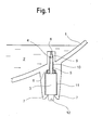
- Fig. 1 is a lower portion of a container 1 of a hot water heater according to the invention shown.
- the container 1 also has an inlet and not shown a drain for water 2 for connection to a water supply network and a heating device to heat the water 2 in the container 1.
- the container 1 has an opening 8 in the lower region shown, which opens from the container interior leads into a substantially cylindrical receptacle 9, 10, 11 in which a Sensor body 4 and a switch 3 with an actuating element 5 in the form of a cylindrical Rod are arranged.
- the sensor body 4 consists of a water-soluble and non-toxic substance such as sugar, table salt or saccharin.
- the desk 3 is designed such that it moves the actuating element 5 upward against the sensor body 4 preloaded.
- the switch 3 is switched off when the actuating element 5 is in the lower off position shown, and turns on when the actuator 5 moved up to an on position. In Fig. 1 the actuator 5 held in the lower off position by the sensor body 4, which is sufficient is firm to withstand the bias of the actuator 5.
- the receptacle for the switch 3, the actuating element 5 and the sensor body 4 has three sections 9, 10, 11 arranged one below the other.
- a top section 9 connects directly to the opening 8 and has a cross section which is essentially corresponds to that of the actuating element 5 and penetration of at least the upper one Section of the actuator 5 in section 9 allows.
- At the bottom of the Section 9 is followed by a central section 10, the cross section of which is larger than that the actuating element 5 and the section 9 and is smaller than that of the switch 3, so that the transition from the middle section 10 to an adjoining one lowest section 11 forms a stop for the switch 3.
- the cross section of the bottom Section 11 is dimensioned so large that the switch 3 is inserted into this section can be.
- Between the middle section 10 and the lowest section 11 is also a small paragraph designed for a sealing ring 6, which is the actuating element 5 seals against the wall of the receptacle 9, 10, 11 and so together with the Actuator 5 tightly closes the container 1.
- the sensor body 4 In order to keep the actuating element 5 in its off position, the sensor body 4 a larger cross section than the top receiving portion 9 and is supported with his upper end against the paragraph between the uppermost section 9 and the middle Section 10 onwards.
- the wall of the lowermost section 11 of the receptacle 9, 10, 11 points vertically at the bottom extending longitudinal slots, the wall sections between the longitudinal slots in Latching hooks 7 for fastening the switch 3 end in the lowest receiving section 11.
- the sensor body 4 is first in the receptacle 9, 10, 11 to the middle Section 10 pushed and then the switch 3 with its actuator 5 inserted into the middle or lowermost receiving section 10 or 11 and by means of the locking hook 7 locked. Then the circuit for the heater can be closed via electrical connections 12 of the switch 3.
- the water 2 reaches the sensor body 4 and begins to dissolve it.
- the switch 3 is turned on and closes the circuit for the heater.
- the opening 8 is located above the Heating device so that at this point there is already enough water 2 in the container 1 is so that even if the heating device is started up immediately, it is generated by it Heat can be absorbed by the water 2.
- the top end of the actuator 5 is pressed by the bracing against the edge of the opening 8, so that there from the actuator 5 to close the container 1 in addition to Sealing ring 6 another sealing point is created.
- a lower portion of the container 1 is shown in section. Along the inner wall of the container 1 extends at least part of a water channel 13. Der Water channel 13 shown is arranged in an inlet to the water heater. about the water channel 13 is water 2 via a connection, not shown Water supply network supplied to the interior of the container 1. On the outside of the container 1, locking hooks 7 are provided, which are used to fasten the switch 3.
- the switch 3 has the actuating element 5. This protrudes above section 10 Actuating element 5 into the water channel 13. The one kept under tension Actuator 5 projects in the on position of the switch over the wall in the Inside of the inlet channel. Switch 3 is in the position shown in the exhibition. At the level of the switch 3 is located within the water channel 13 the sensor body 4.
- the sensor body 4 is designed as a hollow cylinder body 15.
- the cylinder body 15 has a bottom surface with an opening 16.
- the cylinder body 15 is axially inside of the water channel 13 displaceable. In the position shown in Figure 2 is the Cylinder body 15 in its first position.
- the actuating element is in this first position 5 prevented from entering the interior of the water channel 13.
- the switch In the shown Position, the switch is in the off position.
- the cylinder body 15 can have a relatively large game within the water channel 13 because of the cylinder body 15 clamped due to the bias of the actuator 5 in the water channel 13 is. If water 2 is led into the water channel 13 from above, it is due to of the resulting dynamic pressure of the cylinder body 15 pushed down.
- the retention means 17 is by a paragraph formed within the water channel 13. This paragraph narrows at the end of the catchment area 14 the duct waste to a smaller diameter than the diameter of the cylinder body 15.
- a gap is formed, through the supplied water 2 the cylinder body 15 can wash or rinse to get into the interior of the container 1. Because of the retention means 17, the cylinder body 15 is prevented from entering the interior the tank is washed out.
- the holding force, or Force to move the cylinder body 15 can be predetermined.
- the cylinder body 15 more or less quickly from the first position move out and be moved into the collecting space 14. This time delay allows water 2 to enter the interior of the container 1 even before the Cylinder body 15 releases the actuator 5 and the switch in the setting emotional.
- the heater can be prevented from being turned on can, before a minimum amount of water 2 has flowed into the interior of the container 1 is.
Landscapes
- Engineering & Computer Science (AREA)
- Physics & Mathematics (AREA)
- Thermal Sciences (AREA)
- Chemical & Material Sciences (AREA)
- Combustion & Propulsion (AREA)
- Mechanical Engineering (AREA)
- General Engineering & Computer Science (AREA)
- Cookers (AREA)
- Switches Operated By Changes In Physical Conditions (AREA)
- Saccharide Compounds (AREA)
- Sorption Type Refrigeration Machines (AREA)
Abstract
Description
- Fig. 1
- eine Schnittansicht eines Teils eines erfindungsgemäßen Heißwasserbereiters mit einem Fühlerkörper aus wasserlöslichem Stoff,
- Fig. 2
- eine Schnittansicht eines Teils eines erfindungsgemäßen Heißwasserbereiters mit einem nicht löslichen, verschieblichen Fühlerkörper.
Claims (19)
- Elektrischer Heißwasserbereiter mit einem Behälter (1) und einer elektrischen Heizeinrichtung zum Erhitzen des Wassers (2) im Behälter (1), dadurch gekennzeichnet, dass der Heißwasserbereiter einen Schalter (3) mit einem Betätigungselement (5) aufweist, das gegen einen Fühlerkörper (4) in Richtung einer Ein-Stellung vorgespannt ist, in der der Schalter (3) eine Stromzufuhr für die Heizeinrichtung freigibt, wobei der Fühlerkörper (4) derart eingerichtet ist, dass er das Betätigungselement (5) des Schalters (3) ausschließlich im trockenen Zustand in einer Aus-Stellung hält, in der der Schalter (3) die Stromzufuhr für die Heizeinrichtung unterbricht, und der Fühlerkörper (4) mit dem Innenraum des Behälters (1) derart verbunden ist, dass in den Behälter strömendes Wasser (2) den Fühlerkörper (4) erreicht.
- Elektrischer Heißwasserbereiter nach Anspruch 1, dadurch gekennzeichnet, dass der Heißwasserbereiter so eingerichtet ist, dass der Fühlerkörper (4) von in den Behälter (1) einströmenden Wasser (2) erst nach einer bestimmten Zeitdauer soweit verändert wird, dass das Betätigungselement (5) des Schalters (3) in seine Ein-Stellung gelangen kann.
- Elektrischer Heißwasserbereiter nach Anspruch 1 oder 2, dadurch gekennzeichnet, dass der Fühlerkörper (4) über der Heizeinrichtung angeordnet ist.
- Elektrischer Heißwasserbereiter, nach einem der Ansprüche 1 bis 3, dadurch gekennzeichnet, dass das Betätigungselement (5) des Schalters (3) in seiner Ein-Stellung eine Öffnung (8) des Behälters (1) verschließt, die in der Aus-Stellung des Betätigungselements (5) des Schalters (3) den Innenraum des Behälters (1) mit einem Aufnahmeraum (9, 10, 11) für den Schalter (3) verbindet.
- Elektrischer Heißwasserbereiter, nach einem der Ansprüche 1 bis 4, dadurch gekennzeichnet, dass das Betätigungselement (5) des Schalters (3) gegen den Behälter (1) abgedichtet ist.
- Elektrischer Heißwasserbereiter nach einem der Ansprüche 1 bis 5, dadurch gekennzeichnet, dass der Fühlerkörper (4) einen wasserlöslichen und physiologisch unbedenklichen Stoff enthält.
- Elektrischer Heißwasserbereiter nach einem der Ansprüche 1 bis 6, dadurch gekennzeichnet, dass der Fühlerkörper (4) in einem Aufnahmeraum angeordnet ist, der mit dem Innenraum des Behälters (1) derart verbunden ist, dass in dem Aufnahmeraum in den Behälter (1) einströmendes Wasser (2) langsamer steigt als in dem Behälter (1).
- Elektrischer Heißwasserbehälter nach einem der Ansprüche 1 bis 7, dadurch gekennzeichnet, dass der Behälter (1) eine Aufnahme (9, 10, 11) aufweist, die mittels einer ersten Öffnung (8) mit dem Innenraum des Behälters (1) und mittels einer zweiten Öffnung mit dem Außenraum des Behälters (1) verbunden ist, und der Behälter (1) oder die Aufnahme (9, 10, 11) eine Befestigungseinrichtung (7) zum Befestigen des Schalters (3) in der Aufnahme (9, 10, 11) aufweist.
- Elektrischer Heißwasserbereiter nach Anspruch 8, dadurch gekennzeichnet, dass die Aufnahme einen ersten Abschnitt (10) zum Aufnehmen des Fühlerkörpers (4) und des Betätigungselements (5) und einen zweiten Abschnitt (11) zum Aufnehmen des Schalters (3) aufweist und zwischen dem ersten Abschnitt (10) der Aufnahme und dem zweiten Abschnitt (11) der Aufnahme ein Vorsprung als Anschlag für den Schalter (3) ausgestaltet ist.
- Elektrischer Heißwasserbereiter nach Anspruch 8 oder 9, dadurch gekennzeichnet, dass die Befestigungseinrichtung eine Schnappverbindung (7) ist.
- Elektrischer Heißwasserbereiter nach einem der Ansprüche 8 bis 10, dadurch gekennzeichnet, dass die Aufnahme (9, 10, 11) einstückig mit dem Behälter (1) ausgebildet ist.
- Elektrischer Heißwasserbereiter nach einem der Ansprüche 1 bis 5, dadurch gekennzeichnet, dass der Heißwasserbereiter so eingerichtet ist, dass der Fühlerkörper (4) durch einen Staudruck aufgrund des in den Behälter einströmenden oder ausströmenden Wassers (2) von einer ersten Position, in der das Betätigungselement (5) gegen den Fühlerkörper in Richtung der Ein-Stellung des Schalters (3) vorgespannt ist, in eine zweite Position, in der das Betätigungselement (5) des Schalters (3) in seine Ein-Stellung gelangen kann, versetzbar ist.
- Elektrischer Heißwasserbereiter nach Anspruch 12, dadurch gekennzeichnet, dass der Fühlerkörper (4) als axial in einem Wasserkanal (13) verschiebbarer Zylinderkörper (15) ausgebildet ist.
- Elektrischer Heißwasserbereiter nach Anspruch 13, dadurch gekennzeichnet, dass der Zylinderkörper (15) hohlzylindrisch ausgebildet ist und eine Bodenfläche mit einer Öffnung (16) aufweist.
- Elektrischer Heißwasserbereiter nach einem der Ansprüche 12 bis 14, dadurch gekennzeichnet, dass der Fühlerkörper (4) in der zweiten Position in einem Auffangraum (14) aufgenommen ist und der Wasserkanal (13) für ein Durchströmen des Wassers (2) freigegeben ist.
- Elektrischer Heißwasserbereiter nach einem der Ansprüche 13 bis 15, dadurch gekennzeichnet, dass der Auffangraum (14) als ein im Durchmesser erweiterter Teil des Wasserkanals (13) ausgebildet ist.
- Elektrischer Heißwasserbereiter nach Anspruch 16, dadurch gekennzeichnet, dass der Auffangraum (14) einen Rückhaltemittel (17) aufweist, durch den ein Ausschwemmen des Fühlerkörper (4) aus dem Auffangraum (14) verhindert ist.
- Elektrischer Heißwasserbereiter nach einem der Ansprüche 13 bis 17, dadurch gekennzeichnet, dass der Wasserkanal (13), der den Fühlerkörper (4) aufweist, in einem Zulauf für das Wasser (2) in den Innenraum des Behälters (1) angeordnet ist und der Fühlerkörper (4) in seiner ersten Position ein in den Zulauf hineinragendes Betätigungselement (5) des Schalters (3) in seiner Aus-Stellung hält.
- Elektrischer Heißwasserbereiter nach einem der Ansprüche 13 bis 17, dadurch gekennzeichnet, dass der Wasserkanal (13), der den Fühlerkörper (4) aufweist, in einem Auslauf für das Wasser (2) aus dem Innenraum des gefüllten Behälters (1) angeordnet ist und der Fühlerkörper (4) in seiner ersten Position ein in den Auslauf hineinragendes Betätigungselement (5) des Schalters (3) in seiner Aus-Stellung hält.
Priority Applications (1)
| Application Number | Priority Date | Filing Date | Title |
|---|---|---|---|
| EP04014526A EP1491830B1 (de) | 2001-05-30 | 2002-05-29 | Elektrischer Heisswasserbereiter |
Applications Claiming Priority (2)
| Application Number | Priority Date | Filing Date | Title |
|---|---|---|---|
| DE10126333 | 2001-05-30 | ||
| DE10126333A DE10126333B4 (de) | 2001-05-30 | 2001-05-30 | Elektrischer Heißwasserbereiter |
Related Child Applications (1)
| Application Number | Title | Priority Date | Filing Date |
|---|---|---|---|
| EP04014526A Division EP1491830B1 (de) | 2001-05-30 | 2002-05-29 | Elektrischer Heisswasserbereiter |
Publications (2)
| Publication Number | Publication Date |
|---|---|
| EP1262721A1 true EP1262721A1 (de) | 2002-12-04 |
| EP1262721B1 EP1262721B1 (de) | 2005-01-26 |
Family
ID=7686642
Family Applications (2)
| Application Number | Title | Priority Date | Filing Date |
|---|---|---|---|
| EP02011971A Expired - Lifetime EP1262721B1 (de) | 2001-05-30 | 2002-05-29 | Elektrischer Heisswasserbereiter |
| EP04014526A Expired - Lifetime EP1491830B1 (de) | 2001-05-30 | 2002-05-29 | Elektrischer Heisswasserbereiter |
Family Applications After (1)
| Application Number | Title | Priority Date | Filing Date |
|---|---|---|---|
| EP04014526A Expired - Lifetime EP1491830B1 (de) | 2001-05-30 | 2002-05-29 | Elektrischer Heisswasserbereiter |
Country Status (3)
| Country | Link |
|---|---|
| EP (2) | EP1262721B1 (de) |
| AT (2) | ATE337530T1 (de) |
| DE (3) | DE10126333B4 (de) |
Citations (1)
| Publication number | Priority date | Publication date | Assignee | Title |
|---|---|---|---|---|
| US5949960A (en) * | 1997-07-21 | 1999-09-07 | Rheem Manufacturing Company | Electric water heater with dry fire protection system incorporated therein |
Family Cites Families (1)
| Publication number | Priority date | Publication date | Assignee | Title |
|---|---|---|---|---|
| US5998746A (en) * | 1998-04-29 | 1999-12-07 | Chrysler Corporation | Self-adjusting door-ajar switch |
-
2001
- 2001-05-30 DE DE10126333A patent/DE10126333B4/de not_active Expired - Fee Related
-
2002
- 2002-05-29 DE DE50202094T patent/DE50202094D1/de not_active Expired - Lifetime
- 2002-05-29 DE DE50207957T patent/DE50207957D1/de not_active Expired - Lifetime
- 2002-05-29 EP EP02011971A patent/EP1262721B1/de not_active Expired - Lifetime
- 2002-05-29 AT AT04014526T patent/ATE337530T1/de active
- 2002-05-29 EP EP04014526A patent/EP1491830B1/de not_active Expired - Lifetime
- 2002-05-29 AT AT02011971T patent/ATE288055T1/de not_active IP Right Cessation
Patent Citations (1)
| Publication number | Priority date | Publication date | Assignee | Title |
|---|---|---|---|---|
| US5949960A (en) * | 1997-07-21 | 1999-09-07 | Rheem Manufacturing Company | Electric water heater with dry fire protection system incorporated therein |
Also Published As
| Publication number | Publication date |
|---|---|
| EP1491830B1 (de) | 2006-08-23 |
| EP1262721B1 (de) | 2005-01-26 |
| DE10126333B4 (de) | 2012-07-12 |
| ATE288055T1 (de) | 2005-02-15 |
| DE50202094D1 (de) | 2005-03-03 |
| DE50207957D1 (de) | 2006-10-05 |
| EP1491830A3 (de) | 2005-06-29 |
| DE10126333A1 (de) | 2002-12-05 |
| ATE337530T1 (de) | 2006-09-15 |
| EP1491830A2 (de) | 2004-12-29 |
Similar Documents
| Publication | Publication Date | Title |
|---|---|---|
| DE60008553T2 (de) | Elektrisches gerät zum verdampfen einer flüchtigen flüssigkeit | |
| EP1147729B1 (de) | Einspritzdampferzeuger für Kleingeräte | |
| DE2630671C3 (de) | In Verbindung mit einem Klosettbecken verwendbare sanitäre Vorrichtung | |
| DE112016003514T5 (de) | Mischeinheit und Mischbatterie, die eine derartige Mischeinheit umfasst | |
| DE2526736A1 (de) | Klosettsitz mit ventilgesteuerter unterdusche | |
| DE102014225756B4 (de) | Vorrichtung zur elektrischen Auslösung eines Spülvorgangs in einem sanitären Spülkasten | |
| WO1992003081A1 (de) | Espressomaschine | |
| DE2156328C3 (de) | Gerat zur Gesichtspflege mittels Dampf | |
| DE9110171U1 (de) | Dampfreinigungsgerät | |
| DE60216755T2 (de) | Ventilationssystem für haushaltsgeräte, insbesondere für waschmaschinen | |
| DE19709943A1 (de) | Wasserkocher mit Dampfkanal | |
| DE2948462A1 (de) | Elektronischer apparat zum loesen von kesselstein mit einem anzeigegeraet fuer die ausfliessende fluessigkeit | |
| DE4443798C1 (de) | Dampfreinigungsgerät | |
| DE20106868U1 (de) | Dampfreinigungsgerät | |
| DE29818080U1 (de) | Einfach-Reinigungsmittelspender für Geschirrspüler u.ä. | |
| EP1262721B1 (de) | Elektrischer Heisswasserbereiter | |
| DE60223656T2 (de) | "selbstreinigendes, nicht tropfendes bügeleisen" | |
| DE2152021C3 (de) | Anordnung bei einer Geschirrspülmaschine | |
| DE4225827A1 (de) | Offener Warmwasserspeicher | |
| EP0856692A1 (de) | Vorrichtung zur Verstellung des Stössels eines Ventils | |
| DE8501451U1 (de) | Automatischer Wasserkocher | |
| DE9106751U1 (de) | Elektrisch beheizbarer Topf, insbesondere Wasserkocher | |
| EP2933539B1 (de) | Stellvorrichtung für Heizkreisventile | |
| DE19959733B4 (de) | Waschmitteleinbringvorrichtung mit schwimmergeregelter Wasserzufuhr | |
| EP1850712B1 (de) | Elektrischer wasserkocher |
Legal Events
| Date | Code | Title | Description |
|---|---|---|---|
| PUAI | Public reference made under article 153(3) epc to a published international application that has entered the european phase |
Free format text: ORIGINAL CODE: 0009012 |
|
| AK | Designated contracting states |
Kind code of ref document: A1 Designated state(s): AT BE CH CY DE DK ES FI FR GB GR IE IT LI LU MC NL PT SE TR |
|
| AX | Request for extension of the european patent |
Free format text: AL;LT;LV;MK;RO;SI |
|
| 17P | Request for examination filed |
Effective date: 20030604 |
|
| 17Q | First examination report despatched |
Effective date: 20030710 |
|
| AKX | Designation fees paid |
Designated state(s): AT BE CH CY DE DK ES FI FR GB GR IE IT LI LU MC NL PT SE TR |
|
| RAP1 | Party data changed (applicant data changed or rights of an application transferred) |
Owner name: BSH BOSCH UND SIEMENS HAUSGERAETE GMBH |
|
| GRAP | Despatch of communication of intention to grant a patent |
Free format text: ORIGINAL CODE: EPIDOSNIGR1 |
|
| GRAS | Grant fee paid |
Free format text: ORIGINAL CODE: EPIDOSNIGR3 |
|
| GRAA | (expected) grant |
Free format text: ORIGINAL CODE: 0009210 |
|
| AK | Designated contracting states |
Kind code of ref document: B1 Designated state(s): AT BE CH CY DE DK ES FI FR GB GR IE IT LI LU MC NL PT SE TR |
|
| PG25 | Lapsed in a contracting state [announced via postgrant information from national office to epo] |
Ref country code: IT Free format text: LAPSE BECAUSE OF FAILURE TO SUBMIT A TRANSLATION OF THE DESCRIPTION OR TO PAY THE FEE WITHIN THE PRESCRIBED TIME-LIMIT;WARNING: LAPSES OF ITALIAN PATENTS WITH EFFECTIVE DATE BEFORE 2007 MAY HAVE OCCURRED AT ANY TIME BEFORE 2007. THE CORRECT EFFECTIVE DATE MAY BE DIFFERENT FROM THE ONE RECORDED. Effective date: 20050126 Ref country code: NL Free format text: LAPSE BECAUSE OF FAILURE TO SUBMIT A TRANSLATION OF THE DESCRIPTION OR TO PAY THE FEE WITHIN THE PRESCRIBED TIME-LIMIT Effective date: 20050126 Ref country code: FI Free format text: LAPSE BECAUSE OF FAILURE TO SUBMIT A TRANSLATION OF THE DESCRIPTION OR TO PAY THE FEE WITHIN THE PRESCRIBED TIME-LIMIT Effective date: 20050126 Ref country code: TR Free format text: LAPSE BECAUSE OF FAILURE TO SUBMIT A TRANSLATION OF THE DESCRIPTION OR TO PAY THE FEE WITHIN THE PRESCRIBED TIME-LIMIT Effective date: 20050126 Ref country code: GB Free format text: LAPSE BECAUSE OF FAILURE TO SUBMIT A TRANSLATION OF THE DESCRIPTION OR TO PAY THE FEE WITHIN THE PRESCRIBED TIME-LIMIT Effective date: 20050126 Ref country code: IE Free format text: LAPSE BECAUSE OF FAILURE TO SUBMIT A TRANSLATION OF THE DESCRIPTION OR TO PAY THE FEE WITHIN THE PRESCRIBED TIME-LIMIT Effective date: 20050126 Ref country code: FR Free format text: LAPSE BECAUSE OF NON-PAYMENT OF DUE FEES Effective date: 20050126 |
|
| REG | Reference to a national code |
Ref country code: GB Ref legal event code: FG4D Free format text: NOT ENGLISH |
|
| REG | Reference to a national code |
Ref country code: CH Ref legal event code: EP |
|
| REG | Reference to a national code |
Ref country code: IE Ref legal event code: FG4D Free format text: GERMAN |
|
| REF | Corresponds to: |
Ref document number: 50202094 Country of ref document: DE Date of ref document: 20050303 Kind code of ref document: P |
|
| PG25 | Lapsed in a contracting state [announced via postgrant information from national office to epo] |
Ref country code: GR Free format text: LAPSE BECAUSE OF FAILURE TO SUBMIT A TRANSLATION OF THE DESCRIPTION OR TO PAY THE FEE WITHIN THE PRESCRIBED TIME-LIMIT Effective date: 20050426 Ref country code: SE Free format text: LAPSE BECAUSE OF FAILURE TO SUBMIT A TRANSLATION OF THE DESCRIPTION OR TO PAY THE FEE WITHIN THE PRESCRIBED TIME-LIMIT Effective date: 20050426 Ref country code: DK Free format text: LAPSE BECAUSE OF FAILURE TO SUBMIT A TRANSLATION OF THE DESCRIPTION OR TO PAY THE FEE WITHIN THE PRESCRIBED TIME-LIMIT Effective date: 20050426 |
|
| PG25 | Lapsed in a contracting state [announced via postgrant information from national office to epo] |
Ref country code: ES Free format text: LAPSE BECAUSE OF FAILURE TO SUBMIT A TRANSLATION OF THE DESCRIPTION OR TO PAY THE FEE WITHIN THE PRESCRIBED TIME-LIMIT Effective date: 20050507 |
|
| PG25 | Lapsed in a contracting state [announced via postgrant information from national office to epo] |
Ref country code: AT Free format text: LAPSE BECAUSE OF NON-PAYMENT OF DUE FEES Effective date: 20050529 Ref country code: CY Free format text: LAPSE BECAUSE OF FAILURE TO SUBMIT A TRANSLATION OF THE DESCRIPTION OR TO PAY THE FEE WITHIN THE PRESCRIBED TIME-LIMIT Effective date: 20050529 Ref country code: LU Free format text: LAPSE BECAUSE OF NON-PAYMENT OF DUE FEES Effective date: 20050529 |
|
| PG25 | Lapsed in a contracting state [announced via postgrant information from national office to epo] |
Ref country code: MC Free format text: LAPSE BECAUSE OF NON-PAYMENT OF DUE FEES Effective date: 20050531 Ref country code: BE Free format text: LAPSE BECAUSE OF NON-PAYMENT OF DUE FEES Effective date: 20050531 |
|
| NLV1 | Nl: lapsed or annulled due to failure to fulfill the requirements of art. 29p and 29m of the patents act | ||
| GBV | Gb: ep patent (uk) treated as always having been void in accordance with gb section 77(7)/1977 [no translation filed] |
Effective date: 20050126 |
|
| REG | Reference to a national code |
Ref country code: IE Ref legal event code: FD4D |
|
| BERE | Be: lapsed |
Owner name: BSH BOSCH UND SIEMENS HAUSGERATE G.M.B.H. Effective date: 20050531 |
|
| PLBE | No opposition filed within time limit |
Free format text: ORIGINAL CODE: 0009261 |
|
| STAA | Information on the status of an ep patent application or granted ep patent |
Free format text: STATUS: NO OPPOSITION FILED WITHIN TIME LIMIT |
|
| 26N | No opposition filed |
Effective date: 20051027 |
|
| EN | Fr: translation not filed | ||
| PG25 | Lapsed in a contracting state [announced via postgrant information from national office to epo] |
Ref country code: LI Free format text: LAPSE BECAUSE OF NON-PAYMENT OF DUE FEES Effective date: 20060531 Ref country code: CH Free format text: LAPSE BECAUSE OF NON-PAYMENT OF DUE FEES Effective date: 20060531 |
|
| REG | Reference to a national code |
Ref country code: CH Ref legal event code: PL |
|
| BERE | Be: lapsed |
Owner name: BSH BOSCH UND SIEMENS HAUSGERATE G.M.B.H. Effective date: 20050531 |
|
| PG25 | Lapsed in a contracting state [announced via postgrant information from national office to epo] |
Ref country code: PT Free format text: LAPSE BECAUSE OF NON-PAYMENT OF DUE FEES Effective date: 20050626 |
|
| REG | Reference to a national code |
Ref country code: DE Ref legal event code: R081 Ref document number: 50202094 Country of ref document: DE Owner name: BSH HAUSGERAETE GMBH, DE Free format text: FORMER OWNER: BSH BOSCH UND SIEMENS HAUSGERAETE GMBH, 81739 MUENCHEN, DE Effective date: 20150407 |
|
| PGFP | Annual fee paid to national office [announced via postgrant information from national office to epo] |
Ref country code: DE Payment date: 20170531 Year of fee payment: 16 |
|
| REG | Reference to a national code |
Ref country code: DE Ref legal event code: R119 Ref document number: 50202094 Country of ref document: DE |
|
| PG25 | Lapsed in a contracting state [announced via postgrant information from national office to epo] |
Ref country code: DE Free format text: LAPSE BECAUSE OF NON-PAYMENT OF DUE FEES Effective date: 20181201 |