EP1262614B2 - Windkraftanlage - Google Patents
Windkraftanlage Download PDFInfo
- Publication number
- EP1262614B2 EP1262614B2 EP02011704.0A EP02011704A EP1262614B2 EP 1262614 B2 EP1262614 B2 EP 1262614B2 EP 02011704 A EP02011704 A EP 02011704A EP 1262614 B2 EP1262614 B2 EP 1262614B2
- Authority
- EP
- European Patent Office
- Prior art keywords
- tower
- tendons
- foundation
- wall
- concrete
- Prior art date
- Legal status (The legal status is an assumption and is not a legal conclusion. Google has not performed a legal analysis and makes no representation as to the accuracy of the status listed.)
- Expired - Lifetime
Links
Images


Classifications
-
- F—MECHANICAL ENGINEERING; LIGHTING; HEATING; WEAPONS; BLASTING
- F03—MACHINES OR ENGINES FOR LIQUIDS; WIND, SPRING, OR WEIGHT MOTORS; PRODUCING MECHANICAL POWER OR A REACTIVE PROPULSIVE THRUST, NOT OTHERWISE PROVIDED FOR
- F03D—WIND MOTORS
- F03D13/00—Assembly, mounting or commissioning of wind motors; Arrangements specially adapted for transporting wind motor components
- F03D13/20—Arrangements for mounting or supporting wind motors; Masts or towers for wind motors
- F03D13/22—Foundations specially adapted for wind motors
-
- E—FIXED CONSTRUCTIONS
- E04—BUILDING
- E04H—BUILDINGS OR LIKE STRUCTURES FOR PARTICULAR PURPOSES; SWIMMING OR SPLASH BATHS OR POOLS; MASTS; FENCING; TENTS OR CANOPIES, IN GENERAL
- E04H12/00—Towers; Masts or poles; Chimney stacks; Water-towers; Methods of erecting such structures
- E04H12/16—Prestressed structures
-
- F—MECHANICAL ENGINEERING; LIGHTING; HEATING; WEAPONS; BLASTING
- F03—MACHINES OR ENGINES FOR LIQUIDS; WIND, SPRING, OR WEIGHT MOTORS; PRODUCING MECHANICAL POWER OR A REACTIVE PROPULSIVE THRUST, NOT OTHERWISE PROVIDED FOR
- F03D—WIND MOTORS
- F03D13/00—Assembly, mounting or commissioning of wind motors; Arrangements specially adapted for transporting wind motor components
- F03D13/20—Arrangements for mounting or supporting wind motors; Masts or towers for wind motors
-
- F—MECHANICAL ENGINEERING; LIGHTING; HEATING; WEAPONS; BLASTING
- F05—INDEXING SCHEMES RELATING TO ENGINES OR PUMPS IN VARIOUS SUBCLASSES OF CLASSES F01-F04
- F05B—INDEXING SCHEME RELATING TO WIND, SPRING, WEIGHT, INERTIA OR LIKE MOTORS, TO MACHINES OR ENGINES FOR LIQUIDS COVERED BY SUBCLASSES F03B, F03D AND F03G
- F05B2240/00—Components
- F05B2240/90—Mounting on supporting structures or systems
- F05B2240/91—Mounting on supporting structures or systems on a stationary structure
- F05B2240/912—Mounting on supporting structures or systems on a stationary structure on a tower
-
- Y—GENERAL TAGGING OF NEW TECHNOLOGICAL DEVELOPMENTS; GENERAL TAGGING OF CROSS-SECTIONAL TECHNOLOGIES SPANNING OVER SEVERAL SECTIONS OF THE IPC; TECHNICAL SUBJECTS COVERED BY FORMER USPC CROSS-REFERENCE ART COLLECTIONS [XRACs] AND DIGESTS
- Y02—TECHNOLOGIES OR APPLICATIONS FOR MITIGATION OR ADAPTATION AGAINST CLIMATE CHANGE
- Y02E—REDUCTION OF GREENHOUSE GAS [GHG] EMISSIONS, RELATED TO ENERGY GENERATION, TRANSMISSION OR DISTRIBUTION
- Y02E10/00—Energy generation through renewable energy sources
- Y02E10/70—Wind energy
- Y02E10/72—Wind turbines with rotation axis in wind direction
-
- Y—GENERAL TAGGING OF NEW TECHNOLOGICAL DEVELOPMENTS; GENERAL TAGGING OF CROSS-SECTIONAL TECHNOLOGIES SPANNING OVER SEVERAL SECTIONS OF THE IPC; TECHNICAL SUBJECTS COVERED BY FORMER USPC CROSS-REFERENCE ART COLLECTIONS [XRACs] AND DIGESTS
- Y02—TECHNOLOGIES OR APPLICATIONS FOR MITIGATION OR ADAPTATION AGAINST CLIMATE CHANGE
- Y02E—REDUCTION OF GREENHOUSE GAS [GHG] EMISSIONS, RELATED TO ENERGY GENERATION, TRANSMISSION OR DISTRIBUTION
- Y02E10/00—Energy generation through renewable energy sources
- Y02E10/70—Wind energy
- Y02E10/728—Onshore wind turbines
Definitions
- the invention relates to a wind turbine with a tower structure made of prestressed concrete according to the preamble of claim 1.
- Prestressed concrete towers are known in principle. At least one tower section is formed from an annular wall made of concrete.
- the concrete wall can be assembled either by arranging several prefabricated concrete rings one above the other or by a ring formwork, which is filled with concrete.
- About the height of the tower section clamping channels are incorporated into the concrete wall, are retracted into the tendons. These tendons are anchored to the tower crown and anchored below the tower wall on a foundation.
- the tendons are biased during the construction of the tower. Due to the bias is achieved that in all load cases of the tower between the tower crown and foundation concrete wall is subjected to pressure only, whereby the particular suitability of the concrete is utilized to absorb pressure loads and cracking in the concrete is counteracted by excessive tensile forces.
- the clamping channels with the internal tendons are filled after preloading with a cement injection, so that there is an intimate connection of each tendon with the clamping channel in the tower wall.
- a disadvantage of the known prestressed concrete tower structures is that the tower wall is produced in a plurality of sections in a conventional production method and the clamping channels in each newly added segment must be arranged in such a way that they are flush with the underlying clamping channels in the tower wall section already created.
- the corresponding formwork must be provided with precisely adjusted conduits, which are encased in concrete when pouring the formwork.
- there is an increased production cost for a tower construction of prestressed concrete are provided in the clamping channels in the wall for later inclusion of tendons.
- a retightening of the tendons is just as possible as an exchange of tendons in case of damage.
- dismantling a tower structure made of prestressed concrete increased expenses are required to eliminate the cast-in tendons.
- a tower structure is known in which annular segments are stacked and massive tendons are provided to hold them together. It is not a prestressed concrete structure, but a columnar structure, such as a silo of any material, including blow molded plastic parts.
- the tendons extend straight between the foot bearings and head bearings and can not follow a curved contour.
- the DE 835 520 discloses a structure of prestressed concrete, but it is a simple mast with a small width and only one tendon, which runs on the central axis. Apart from the fact that for towers on the periphery several tendons must be present, the central arrangement would also obstruct internals in the tower interior such as stairs, elevators and mezzanines massive.
- a retightening of the tendons is just as possible as an exchange of tendons in case of damage.
- dismantling a tower structure made of prestressed concrete increased expenses are required to eliminate the cast-in tendons.
- the arrangement of the tendons in the cavity in the interior of the annular concrete wall of the tower section has the particular advantage that the tendons are always accessible to be inspected, re-tensioned or replaced. When dismantling a tower, the tendons can be removed, so that only a conventional concrete structure remains, which can be dismantled in a known manner.
- the production of the tower wall can be done much faster and cheaper, since in the formwork for the construction of the concrete wall no more clamping channels must be installed and adjusted. Furthermore, it is possible to retighten the tendons if necessary, for example, if larger bending moments are introduced to the concrete tower section by conversions on the spire than originally provided.
- the tendons can also be retrofitted to adapt to the traffic loads on the tower structure and z. B. also be replaced by larger tendons.
- FIG. 1 a tower construction 100 is shown.
- a foundation 10 made of reinforced concrete is also made of concrete tower wall 20 is constructed, which has an annular cross section, ie a closed cross-section, which may be circular, ellipsoidal or polygonal in particular.
- a tower crown 30 is placed, which may be formed of concrete or steel.
- the tower crown 30 can also serve as an adapter segment to which an additional steel mast 40 can be fastened.
- the tower crown can be designed as a steel mast.
- the annular tower wall 20 encloses an internal cavity 22, in which, for example, staircases or freight or passenger lifts can be arranged.
- a plurality of head bearing elements 32 are arranged distributed over the circumference, in which the tendons 24 are anchored.
- the tendons 24 extend from the head bearing element 32 on the turret 30 along the inside of the tower wall 20 into a so-called tensioning cell 14 in the foundation 10.
- a plurality of favorlager electroden 12 are arranged.
- the retraction of the tendons 24 in the tower structure 100 according to the invention is simple, since the tendons 24 are always accessible in the cavity 22.
- the tendons 24 may be inserted directly from a raised to the height of the turret 30 roller in a through hole on the head bearing member 32, a fixed anchor, and then unwound until they reach a through hole on the contemplatlagerelement 12, a clamping anchor.
- the tendons 24 are gripped on the adoptedlager electroden 12 by means of clamping presses and brought to a certain voltage. With the tendons 24 is, as is well known, between the foundation 10 and tower crown 30 arranged tower wall 20 made of concrete subjected to a compressive stress. Finally, the tendons 24 in the prestressed position in the contemplatlagerelement 12, the clamping anchor, wedged. On the protruding from the contemplatlager 12 ends, as in particular FIG. 4 shows, a cladding tube 18 slipped. This is removable and allows the later a-bermalige fitting a clamping press to change the bias of the tendons 24th
- the tension can also be applied to the tower crown if the fixed anchors are arranged on the foundation 10 and the tension anchors on the tower crown 30.
- long tendons 24 In order to counteract oscillations of the live, long tendons 24, these can be fastened to the tower wall 20 via one or more fastening elements 26.
- the fasteners 26 allow axial displacement of the attached tendon 24th
- a tendon 24 shown which is composed of several tensioning cables 24.1 ... 24.4 and preferably prefabricated by the factory.
- the tensioning cables 24.1 ... 24.4 each consist of struck strands and are protected against corrosion with a tensioning cable sheath.
- the tension cable sheath is still pressed with corrosion protection grease, so that the strands are coated with grease. Overall, this results in a permanent corrosion protection.
- the tendons 24 sit in the in the FIGS. 3a and 3b illustrated embodiments of four clamping cables 24.1 ... 24.4 together, which are arranged in a line next to each other.
- the tension cables can at least partially also be arranged one above the other.
- the tensioning cables can have smaller or larger cross sections for themselves.
- the load capacity of the tendon 24 can be changed by the number of its combined chip cable.
- a comb-like fastening element 26 ' is provided, via which the tensioning cables 24.1... 24.4 are individually clamped and fastened to the tower wall 20.
- This fastening element 26 ' has the advantage that the tensioning cables 24.1... 24.4 are held at a distance from one another and vibrations of the tensioning cables in a direction parallel to the inner circumference of the tower wall 20 are prevented.
- Fig. 2 shows the anchoring of the tendons 24 on the tower crown 30.
- the tendons 24 in the field of tower crown 30 in their individual tensioning cable 24.1, 24.2 fanned out.
- the tensioning cables 24.1, 24.2 run individually through through holes in the tower crown 30 and are each anchored in a head bearing element 32.
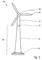
- the tower construction 100 described is particularly suitable for the construction of large wind turbines, as in FIG. 5 shown.
- Wind turbines with towers of high altitude are usually built in cycles with the help of climbing or sliding formwork.
- the arrangement of the tendons 24 in the cavity 22 in the interior of the tower wall 20 a simple manufacture of the tower construction 100 is possible, since according to the invention no more clamping channels must be incorporated into the tower wall 20.
- wind turbine 200 consists essentially of a described tower structure 100 with a height of about 70m above ground and an outer diameter of the tower wall 20, which tapers from about 12m at the foundation 10 to 4.40 m in the tower crown.
- Described trained tower structures made of chipboard with other dimensions are possible according to the use and static-dynamic calculation.
- the tower structure 100 is extended by a patch on the tower crown 30 steel mast 40, on which in turn a nacelle with generator 50 and rotor 60 is placed.
- the tower crown 30 represents as an adapter element, the connecting element between the prestressed reinforced concrete tower 100 and the generator or the attached steel mast 40.
Description
- Die Erfindung betrifft eine Windkraftanlage mit einem Turmbauwerk aus Spannbeton nach dem Oberbegriff des Anspruchs 1.
- Türme aus Spannbeton sind grundsätzlich bekannt. Wenigstens ein Turmabschnitt ist dabei aus einer ringförmigen Wandung aus Beton gebildet. Die Betonwandung kann entweder durch Anordnung mehrerer vorgefertigter Betonringe übereinander zusammengesetzt werden oder durch eine Ringschalung, die mit Beton ausgefüllt wird. Über die Höhe des Turmabschnitts sind Spannkanäle in die Betonwandung eingearbeitet, in die Spannglieder eingezogen sind. Diese Spannglieder sind an der Turmkrone verankert und unterhalb der Turmwandung an einem Fundament verankert. Die Spannglieder werden beim Bau des Turms mit einer Vorspannung beaufschlagt. Durch die Vorspannung wird erreicht, dass in allen Lastfällen des Turmes die zwischen Turmkrone und Fundament befindliche Betonwandung ausschließlich auf Druck beansprucht wird, wodurch die besondere Eignung des Betons zur Aufnahme von Drucklasten ausgenutzt wird und einer Rißbildung im Beton durch zu hohe Zugkräfte entgegengewirkt wird. Die Spannkanäle mit den innenliegenden Spanngliedern werden nach dem Vorspannen mit einer Zementinjektion gefüllt, so dass sich eine innige Verbindung jedes Spannglieds mit dem Spannkanal in der Turmwandung ergibt.
- Nachteilig bei den bekannten Turmbauwerken aus Spannbeton ist, dass bei einer üblichen Fertigungsweise die Turmwandung in mehreren Abschnitten hergestellt wird und dabei die Spannkanäle in jedem neu hinzuzufügenden Segment so angeordnet sein müssen, dass sie bündig mit den unterhalb liegenden Spannkanälen in dem bereits erstellten Turmwandungsabschnitt sind. Die entsprechenden Schalungen müssen dazu mit genau justierten Leerrohren versehen sein, die beim Ausgießen der Schalung mit Beton umhüllt werden. Insgesamt ergibt sich ein erhöhter Fertigungsaufwand für ein Turmbauwerk aus Spannbeton, bei dem Spannkanäle in der Wandung zur späteren Aufnahme von Spanngliedern vorgesehen sind.
- Das Ausfüllen der Hohlräume in den Spannkanälen mit den innenliegenden Spanngliedern ist, insbesondere bei großen Spannkanallängen bei großen Turmhöhen und/oder wegen der geringen Spannkanalquerschnitte, schwierig. Eine zuverlässige Kontrolle der Verfüllung des Spannkanals über dessen Länge hinweg ist nicht möglich. An den Stellen, wo die Spannglieder nicht von einer Zementinjektion umhüllt sind, können später Korrosionsschäden entstehen; Lunker im Injektionsmaterial in den Spannkanälen können jedoch nicht festgestellt werden. Korrosion bewirkt ein Versagen der Spannglieder und beeinträchtigt die Gebrauchsfähigkeit des Turmes.
- Ein Nachspannen der Spannglieder ist ebensowenig möglich wie ein Austausch von Spanngliedern im Schadensfall. Beim Rückbau eines Turmbauwerkes aus Spannbeton sind erhöhte Aufwendungen erforderlich, um die einbetonierten Spannglieder zu beseitigen.
- Aus der
GB 11 051 33 - Die
DE 835 520 offenbart ein Bauwerk aus Spannbeton, wobei es sich jedoch um einen einfachen Mast mit geringer Weite und nur einem Spannglied handelt, welches auf der Mittelachse verläuft. Abgesehen davon, dass für Türme am Umfang mehrere Spannglieder vorhanden sein müssen, würde die zentrale Anordnung auch Einbauten im Turminneren wie Treppen, Fahrstühle und Zwischengeschosse massiv behindern. - Ein Nachspannen der Spannglieder ist ebensowenig möglich wie ein Austausch von Spanngliedern im Schadensfall. Beim Rückbau eines Turmbauwerkes aus Spannbeton sind erhöhte Aufwendungen erforderlich, um die einbetonierten Spannglieder zu beseitigen.
- Es stellt sich daher die Aufgabe, ein Turmbauwerk der eingangs genannten Art so weiter zu entwickeln, dass die Fertigung der Turmwandung vereinfacht ist, dass der Korrosion der Spannglieder entgegen gewirkt wird und damit die Dauerhaftigkeit des Turms erhöht ist. Auch soll der Rückbau des Turmbauwerks erleichtert sein.
- Diese Aufgaben werden durch die kennzeichnenden Merkmale des Anspruchs 1 gelöst. Die Anordnung der Spannglieder im Hohlraum im Inneren der ringförmigen Betonwandung des Turmabschnitts hat insbesondere den Vorteil, dass die Spannglieder jederzeit zugänglich sind, um inspiziert, nachgespannt oder ausgetauscht zu werden. Beim Rückbau eines Turmes können die Spannglieder ausgebaut werden, so dass lediglich ein übliches Betonbauwerk übrig bleibt, das auf bekannte Weise zerlegbar ist.
- Die Fertigung der Turmwandung kann wesentlich schneller und kostengünstiger erfolgen, da in der Schalung zum Bau der Betonwandung keine Spannkanäle mehr eingebaut und justiert werden müssen. Weiterhin ist es möglich, die Spannglieder bei Bedarf nachzuspannen, beispielsweise wenn durch Umbauten auf der Turmspitze größere Biegemomente auf den Betonturmabschnitt eingeleitet werden, als ursprünglich vorgesehen. Damit ist das erfindungsgemäße Turmbauwerk besonders für Windkraftanlagen geeignet; falls bei einer späteren Umrüstung, z. B. Verlängerung mit einem Stahlmast und/oder Anordnung eines Generators und Rotors mit höherer Masse, eine höhere Biegebeanspruchung des Betonturmabschnittes auftreten sollte, so ist es möglich, die Vorspannung soweit zu erhöhen, dass gewährleistet bleibt, dass eine Belastung der Betonturmwandung in allen Betriebssituationen im Druckbereich erfolgt und somit Risse im Beton vermieden werden. Die Spannglieder können zur Anpassung an die Verkehrslasten am Turmbauwerk auch nachträglich ausgetauscht werden und z. B. auch durch größere Spannglieder ersetzt werden.
- Weitere vorteilhafte Ausgestaltungen der Erfindung sind den Unteransprüchen und dem nachfolgend mit Bezug auf die Zeichnung erläuterten Ausführungsbeispiel zu entnehmen.
- Die Figuren zeigen im einzelnen:
- Fig. 1
- Ansicht eines Turmbauwerks eines erfindungsgemäßen Windkraftwerks; in Schnittansicht;
- Fig. 2
- die Verankerung der Spannglieder im Bereich der Turmkrone im Detail;
- Fig. 3a,b
- die Befestigung der Spannglieder an der Turmwandung im Detail;
- Fig. 4
- die Verankerung der Spannglieder im Fundament im Detail; und
- Fig. 5
- eine Windkraftanlage mit einem erfindungsgemäßen Turmbauwerk in Vorderansicht.
- In
Figur 1 ist ein Turmbauwerk 100 dargestellt. Auf einem Fundament 10 aus Stahlbeton ist eine gleichfalls aus Beton bestehende Turmwandung 20 errichtet, die einen ringförmigen Querschnitt hat, also einen geschlossenen Querschnitt, der insbesondere kreisförmig, ellipsoid oder auch polygonal sein kann. Auf die Turmwandung 20 ist eine Turmkrone 30 aufgesetzt, die aus Beton oder aus Stahl gebildet sein kann. Die Turmkrone 30 kann auch als Adaptersegment dienen, an dem ein zusätzlicher Stahlmast 40 befestigbar ist. Weiterhin kann die Turmkrone als Stahlmast ausgebildet sein. - Die ringförmige Turmwandung 20 umschließt einen innenliegenden Hohlraum 22, in dem beispielsweise Treppenaufgänge oder Lasten- bzw. Personenaufzüge angeordnet sein können.
- An der Turmkrone 30 sind über deren Umfang verteilt eine Vielzahl von Kopflagerelementen 32 angeordnet, in denen die Spannglieder 24 verankert sind. Die Spannglieder 24 erstrecken sich von dem Kopflagerelement 32 an der Turmkrone 30 entlang der Innenseite der Turmwandung 20 bis in einen sogenannten Spannkeller 14 im Fundament 10. Hier sind eine Vielzahl von Fußlagerelementen 12 angeordnet.
- Das Einziehen der Spannglieder 24 bei dem erfindungsgemäßen Turmbauwerk 100 ist einfach, da die Spannglieder 24 in dem Hohlraum 22 stets zugänglich sind. Die Spannglieder 24 können direkt von einer auf die Höhe der Turmkrone 30 gehobenen Rolle in eine Durchgangsbohrung am Kopflagerelement 32, einem Festanker, eingeführt und dann abgespult werden, bis sie eine Durchgangsbohrung an dem Fußlagerelement 12, einem Spannanker, erreichen.
- Ebenso ist es möglich, die Spannglieder 24 zuerst in das Fußlagerelement 12 einzusetzen und dann mit Hilfe eines Hilfsseils zur Turmkrone 30 hochzuziehen. Auch in diesem Fall erleichtert die freie Zugänglichkeit der Spannglieder 24 die Montage wesentlich.
- Die Spannglieder 24 werden an den Fußlagerelementen 12 mit Hilfe von Spannpressen gegriffen und auf eine bestimmte Spannung gebracht. Mit den Spanngliedern 24 wird so, wie an sich bekannt, die zwischen Fundament 10 und Turmkrone 30 angeordnete Turmwandung 20 aus Beton mit einer Druckspannung beaufschlagt. Abschließend werden die Spannglieder 24 in der vorgespannten Stellung im Fußlagerelement 12, dem Spannanker, verkeilt. Auf die aus dem Fußlager 12 herausragenden Enden wird, wie insbesondere
Figur 4 zeigt, ein Hüllrohr 18 gestülpt. Dieses ist entfernbar und erlaubt das spätere a-bermalige Ansetzen einer Spannpresse zur Veränderung der Vorspannung der Spannglieder 24. - Die Spannung kann auch an der Turmkrone aufgebracht werden, wenn die Festanker am Fundament 10 und die Spannanker an der Turmkrone 30 angeordnet sind.
- Um Schwingungen der unter Spannung stehenden, langen Spannglieder 24 entgegenzuwirken, können diese über ein oder mehrere Befestigungselemente 26 an der Turmwandung 20 befestigt sein. Die Befestigungselemente 26 erlauben eine axiale Verschiebbarkeit des befestigten Spannglieds 24.
- In
Fig. 3a und 3b ist jeweils ein Spannglied 24 dargestellt, das sich aus mehreren Spannkabeln 24.1...24.4 zusammensetzt und vorzugsweise werkmäßig vorgefertigt ist. Die Spannkabel 24.1...24.4 bestehen jeweils aus geschlagenen Litzen und sind mit einer Spannkabelhülle vor Korrosion geschützt. Außerdem ist die Spannkabelhülle noch mit Korrosionsschutzfett verpresst, so dass die Litzen fettumhüllt sind. Insgesamt ergibt sich so ein dauerhafter Korrosionsschutz. - Die Spannglieder 24 setzen sich in den in den
Figuren 3a und 3b dargestellten Ausführungsbeispielen aus je vier Spannkabeln 24.1...24.4 zusammen, die in einer Linie nebeneinander angeordnet sind. Die Spannkabel können aber wenigstens teilweise auch übereinander angeordnet sein. Je nach Belastung können die Spannkabel für sich kleinere oder größere Querschnitte haben. Außerdem kann die Belastbarkeit des Spanngliedes 24 über die Zahl seiner zusammengefassten Spankabel verändert werden. - Bei der Ausführungsform gemäß
Figur 3a sind die Spannkabel 24.1...24.4 von einer zusätzlichen Spanngliedhülle 25 umgeben und über diese mit einem Befestigungselement 26 an der Turmwandung 20 verbunden. - Bei der Ausführungsform gemäß
Figur 3a ist ein kammartiges Befestigungselement 26' vorgesehen, über das die Spannkabel 24.1...24.4 einzeln eingeklemmt und an der Turmwandung 20 befestigt sind. Bei diesem Befestigungselement 26' ergibt sich der Vorteil, dass die Spannkabel 24.1...24.4 auf Distanz voneinander gehalten werden und Schwingungen der Spannkabel in einer Richtung parallel zum Innenumfang der Turmwandung 20 unterbunden werden. -
Fig. 2 zeigt die Verankerung der Spannglieder 24 an der Turmkrone 30. Bevorzugt sind die Spannglieder 24 im Bereich der Turmkrone 30 in ihre einzelnen Spannkabel 24.1, 24.2 aufgefächert. Die Spannkabel 24.1, 24.2 laufen einzeln durch Durchgangsbohrungen in der Turmkrone 30 und sind jeweils in einem Kopflagerelement 32 verankert. - Das beschriebene Turmbauwerk 100 eignet sich insbesondere zum Bau von großen Windkraftanlagen, wie in
Figur 5 gezeigt. Windkraftanlagen mit Türmen großer Höhe werden üblicherweise taktweise mit Hilfe von Kletter- oder Gleitschalungen errichtet. Durch die Anordnung der Spannglieder 24 im Hohlraum 22 im Inneren der Turmwandung 20 ist eine einfache Fertigung des Turmbauwerks 100 möglich, da gemäß der Erfindung keine Spannkanäle mehr in die Turmwandung 20 eingearbeitet werden müssen. - Die in
Figur 5 dargestellte Windkraftanlage 200 besteht im wesentlichen aus einem beschriebenen Turmbauwerk 100 mit einer Höhe von etwa 70m über Grund und einem Außendurchmesser der Turmwandung 20, der sich ausgehend von ca. 12m am Fundament 10 bis auf 4,40 m im Bereich der Turmkrone verjüngt. Beschriebene ausgebildete Turmbauwerke aus Spanbeton mit anderen Abmessungen sind entsprechend der Nutzung und statisch-dynamischer Berechnung möglich. - Das Turmbauwerk 100 ist durch einen auf die Turmkrone 30 aufgesetzten Stahlmast 40 verlängert, auf dem wiederum eine Gondel mit Generator 50 und Rotor 60 aufgesetzt ist. Die Turmkrone 30 stellt als Adapterelement das Verbindungselement zwischen dem vorgespannten Stahlbetonturm 100 und dem Generator bzw. dem aufgesetzten Stahlmast 40 dar. Bei Anordnung eines aufgesetzten Stahlmastes kann bei entsprechender Fußausbildung dieser die Funktion der Turmkrone übernehmen bzw. die Turmkrone in Form eines Stahlmasts ausgebildet sein.
Claims (1)
- Windkraftanlage (200), wenigstens bestehend aus einem Turmbauwerk (100) aus Spannbeton mit- einem Fundament (10)- wenigstens einer auf dem Fundament (10) errichteten Turmwandung (20) mit ringförmigem Querschnitt und einem davon umfassten, innenliegenden Hohlraum (22)- und einer auf die Turmwandung (20) aufgesetzten Turmkrone (30),
und aus einem auf der Turmkrone (30) angeordneten Generator (50) mit einem Rotor (60),
wobei- sich zwischen dem Fundament (10) und der Turmkrone (30) wenigstens drei Spannglieder (24) erstrecken, die außerhalb der Turmwandung (20) durch den Hohlraum (22) geführt sind und durch die die Turmwandung (20) mit einer Vorspannung beaufschlagbar ist,- die Spannglieder (24) an einem Kopflagerelement (32) in der Turmkrone (30) verankert sind und an einem Fußlagerelement (12) im Fundament (10) spannbar angeordnet sind oder dass die Spannglieder (24) an einem Fußlager (12) im Fundament (10) verankert sind und an einem Kopflagerelement (32) in der Turmkrone (30) spannbar angeordnet sind,- die Spannglieder (24) aus wenigstens einem Spannkabel (24.1...24.4) gebildet sind, welches aus einer Anordnung aus Stahllitzen besteht, die von einer Mantelhülle umgeben ist, wobei die Zwischenräume zwischen den Stahllitzen und/oder zwischen den Stahllitzen und der Mantelhülle mit einer Fettpackung verpresst sind, und mit wenigstens einem Befestigungselement (26) an der Turmwandung (20) befestigt sind, und- die Turmkrone (30) als Adapterelement das Verbindungselement zwischen dem vorgespannten Turmbauwerk (100) aus Stahlbeton und dem Generator bzw. dem aufgesetzten Stahlmast (40) darstellt oder die Turmkrone (30) als Stahlmast ausgebildet ist.
Applications Claiming Priority (2)
| Application Number | Priority Date | Filing Date | Title |
|---|---|---|---|
| DE10126912 | 2001-06-01 | ||
| DE10126912A DE10126912A1 (de) | 2001-06-01 | 2001-06-01 | Turmbauwerk aus Spannbeton |
Publications (4)
| Publication Number | Publication Date |
|---|---|
| EP1262614A2 EP1262614A2 (de) | 2002-12-04 |
| EP1262614A3 EP1262614A3 (de) | 2003-12-03 |
| EP1262614B1 EP1262614B1 (de) | 2008-09-10 |
| EP1262614B2 true EP1262614B2 (de) | 2015-03-18 |
Family
ID=7687013
Family Applications (1)
| Application Number | Title | Priority Date | Filing Date |
|---|---|---|---|
| EP02011704.0A Expired - Lifetime EP1262614B2 (de) | 2001-06-01 | 2002-05-25 | Windkraftanlage |
Country Status (5)
| Country | Link |
|---|---|
| EP (1) | EP1262614B2 (de) |
| AT (1) | ATE408048T1 (de) |
| DE (2) | DE10126912A1 (de) |
| DK (1) | DK1262614T3 (de) |
| ES (1) | ES2315328T3 (de) |
Cited By (2)
| Publication number | Priority date | Publication date | Assignee | Title |
|---|---|---|---|---|
| WO2019025505A1 (de) | 2017-08-01 | 2019-02-07 | Max Bögl Wind AG | Fundament für ein bauwerk |
| US10316537B2 (en) | 2015-04-14 | 2019-06-11 | Wobben Properties Gmbh | Tension cord guide in a wind turbine tower |
Families Citing this family (49)
| Publication number | Priority date | Publication date | Assignee | Title |
|---|---|---|---|---|
| NL1019953C2 (nl) * | 2002-02-12 | 2002-12-19 | Mecal Applied Mechanics B V | Geprefabriceerde toren of mast, alsmede een methode voor het samenvoegen en/of naspannen van segmenten die één constructie moeten vormen, alsmede een werkwijze voor het opbouwen van een toren of mast bestaande uit segmenten. |
| ES2685834T3 (es) * | 2006-06-30 | 2018-10-11 | Vestas Wind Systems A/S | Una torre de turbina eólica y método para alterar la frecuencia propia de una torre de turbina eólica |
| DE102007031065B4 (de) | 2007-06-28 | 2011-05-05 | Nordex Energy Gmbh | Windenergieanlagenturm |
| WO2009056898A1 (es) | 2007-11-02 | 2009-05-07 | Alejandro Cortina-Cordero | Torre de concreto postensado para generadores eolicos |
| US20100006710A1 (en) * | 2008-07-08 | 2010-01-14 | General Electric Company | Cable bridge for a wind turbine tower |
| WO2010006659A1 (en) | 2008-07-15 | 2010-01-21 | Siemens Aktiengesellschaft | Method for the assembly of a tower and tower |
| DE102008053454B4 (de) | 2008-10-28 | 2012-07-19 | Gisela Wendling-Lenz | Hybrides Turmbauwerk |
| IT1400073B1 (it) | 2009-09-11 | 2013-05-17 | Stefano Knisel | Fondazione migliorata per torre eolica |
| IT1396433B1 (it) * | 2009-11-16 | 2012-11-23 | Rolic Invest Sarl | Impianto eolico per la generazione di energia elettrica e metodo per realizzare un pilone del suddetto impianto eolico. |
| DK2330263T3 (en) | 2009-12-01 | 2016-06-06 | Siemens Ag | concrete Tower |
| ES2590977T3 (es) * | 2009-12-23 | 2016-11-24 | Soletanche Freyssinet | Torre con una columna de hormigón pretensada y método de construcción |
| WO2011091799A1 (en) * | 2010-02-01 | 2011-08-04 | Conelto Aps | A tower construction and a method for erecting the tower construction |
| EP2354536A1 (de) * | 2010-02-02 | 2011-08-10 | Siemens Aktiengesellschaft | Stützstruktur zur Stützung einer Offshore-Windturbine |
| FI122076B (fi) * | 2010-03-12 | 2011-08-15 | Peikko Group Oy | Menetelmä tornimaisten rakenteiden perustusten yhteydessä ja tornimaisten rakenteiden perustus |
| DK2374966T3 (en) | 2010-04-06 | 2016-11-07 | Soletanche Freyssinet | A method of building a hybrid tower for a wind turbine |
| US8307593B2 (en) | 2010-08-18 | 2012-11-13 | General Electric Company | Tower with adapter section |
| WO2012075607A1 (en) * | 2010-12-09 | 2012-06-14 | General Electric Company | Methods and systems for assembling wind turbine tower |
| KR101383162B1 (ko) * | 2012-08-08 | 2014-04-09 | 한국해양과학기술원 | 다단형 프리스트레스를 통한 모듈러 풍력타워 |
| GB201215004D0 (en) | 2012-08-23 | 2012-10-10 | Blade Dynamics Ltd | Wind turbine tower |
| WO2014037421A1 (de) * | 2012-09-04 | 2014-03-13 | Philipp Wagner | Turmbauwerk einer windenergieanlage und verfahren zu seiner herstellung |
| GB201217210D0 (en) | 2012-09-26 | 2012-11-07 | Blade Dynamics Ltd | A metod of forming a structural connection between a spar cap fairing for a wind turbine blade |
| GB201217212D0 (en) | 2012-09-26 | 2012-11-07 | Blade Dynamics Ltd | Windturbine blade |
| WO2014095330A1 (de) * | 2012-12-18 | 2014-06-26 | Wobben Properties Gmbh | Anker, spannvorrichtung, windenergieanlage und verfahren zum zugspannen von zugsträngen an einem anker |
| DE102013002472A1 (de) * | 2013-02-13 | 2014-08-14 | Strabag Offshore Wind Gmbh | "Schwerkraftfundament für ein Offshore-Bauwerk" |
| US9032674B2 (en) | 2013-03-05 | 2015-05-19 | Siemens Aktiengesellschaft | Wind turbine tower arrangement |
| CN103147935A (zh) * | 2013-03-27 | 2013-06-12 | 湘电风能有限公司 | 一种风力发电机组塔筒及风电发电机组 |
| DE102013105512A1 (de) * | 2013-05-29 | 2014-12-04 | Max Bögl Wind AG | Betonfundament und Verfahren zur Herstellung eines Betonfundaments für einen Windkraftturm sowie Positioniervorrichtung zur Positionierung von Hüllrohren in einem Betonfundament |
| DE102013211750A1 (de) * | 2013-06-21 | 2014-12-24 | Wobben Properties Gmbh | Windenergieanlage und Windenergieanlagen-Fundament |
| DE102013108692A1 (de) | 2013-08-12 | 2015-02-12 | Max Bögl Wind AG | Turm mit wenigstens einem Turmabschnitt mit Faserspanngliedern |
| CN103422702A (zh) * | 2013-09-11 | 2013-12-04 | 祁锦明 | 两端为内法兰连接的预应力混凝土杆段 |
| DE102013221956A1 (de) * | 2013-10-29 | 2015-04-30 | Wobben Properties Gmbh | Litzenvorverkeilvorrichtung und ein Verfahren zum Herstellen von Spannglied-Festankern |
| DE102013226536A1 (de) * | 2013-12-18 | 2015-06-18 | Wobben Properties Gmbh | Anordnung mit einem Betonfundament und einem Turm und Verfahren zum Errichten eines Turms |
| WO2016119035A1 (pt) * | 2015-01-30 | 2016-08-04 | Proacqua Construções E Comércio Ltda. | Torre de materiais estruturais e método de montagem |
| CN105020543B (zh) * | 2015-07-31 | 2017-12-29 | 大连华锐重工集团股份有限公司 | 一种预应力底座组 |
| DE102016115042A1 (de) | 2015-09-15 | 2017-03-30 | Max Bögl Wind AG | Turm für eine Windkraftanlage aus ringsegmentförmigen Betonfertigteilen |
| BR102016023743B1 (pt) * | 2016-10-11 | 2022-11-29 | Protende Sistemas E Métodos De Construções Ltda | Torre de concreto estrutural e método de montagem |
| CN106567600B (zh) * | 2016-10-20 | 2019-03-01 | 国网河南偃师市供电公司 | 一种绝缘水泥电线杆 |
| CN106523295A (zh) * | 2016-11-10 | 2017-03-22 | 中国电建集团华东勘测设计研究院有限公司 | 逐级变径式现浇混凝土风电机组塔架 |
| DE102017203645B4 (de) | 2017-03-07 | 2020-07-02 | KB Vorspann-Technik GmbH | System zum Vorspannen eines Turmbauwerks |
| EP3372753B1 (de) * | 2017-03-07 | 2020-02-19 | KB Vorspann-Technik GmbH | Verfahren, arretiervorrichtung und system zum vorspannen eines turmbauwerks |
| DE102017204566A1 (de) | 2017-03-20 | 2018-09-20 | KB Vorspann-Technik GmbH | Seilführung zum beschädigungsfreien Führen eines Seils sowie entsprechendes Verfahren |
| CN108930636A (zh) * | 2017-05-24 | 2018-12-04 | 上海电气风电集团有限公司 | 陆上型风机支撑结构 |
| DE102018112857A1 (de) * | 2017-12-13 | 2019-06-13 | Universelle-Fertigteil-Fundamente GmbH | Fundament für eine Windkraftanlage |
| DE102018108945A1 (de) | 2018-04-16 | 2019-10-17 | Wobben Properties Gmbh | Verfahren zum Errichten eines Windenergieanlagen-Turms |
| CN111287907B (zh) * | 2018-12-06 | 2021-02-23 | 深圳京创重工特种工程有限公司 | 混凝土塔筒的施工方法 |
| DE102019129354A1 (de) | 2019-10-30 | 2021-05-06 | Max Bögl Wind AG | Mit wenigstens einem Spannglied vorgespanntes Bauwerk sowie Verfahren zur Herstellung eines mit wenigstens einem Spannglied vorgespannten Bauwerks |
| CN113062649B (zh) * | 2021-03-31 | 2022-01-18 | 重庆大学 | 一种基于参数设计计算的预应力调谐质量阻尼器安装方法 |
| CN113294022B (zh) * | 2021-05-06 | 2022-12-27 | 上海市机电设计研究院有限公司 | 利用风电塔筒基础预应力索预留孔的钢绞线穿束方法 |
| WO2023194629A1 (es) * | 2022-04-05 | 2023-10-12 | Windtechnic Engineering S.L. | Estructura vertical de hormigón con pretensado variable y aerogenerador con dicha estructura |
Family Cites Families (12)
| Publication number | Priority date | Publication date | Assignee | Title |
|---|---|---|---|---|
| GB638089A (en) | 1946-08-13 | 1950-05-31 | Eugene Hippolyte Garnier | Improvements in the construction of poles for power transmission or the like |
| DE835520C (de) | 1949-03-06 | 1952-06-13 | Bbc Brown Boveri & Cie | Betonmast |
| DE1434785A1 (de) | 1964-03-02 | 1968-11-28 | Fritz Reinke | Aus Fertigteilen zusammengesetzter Hohlkoerper |
| DE2249198B1 (de) * | 1972-10-05 | 1973-10-11 | Steffens & Noelle Gmbh, 1000 Berlin | Turmartiges Bauwerk |
| DE3806759C2 (de) * | 1988-03-02 | 1998-06-04 | Dyckerhoff & Widmann Ag | Verfahren zum Sanieren eines hohlzylindrischen Baukörpers und Bausatzsystem hierzu |
| DE59001339D1 (de) * | 1989-04-12 | 1993-06-09 | Vorspann Technik Gmbh | Spannbuendel aus mehreren spanngliedern wie litzen, staeben oder draehten. |
| DE4001577A1 (de) | 1990-01-20 | 1991-07-25 | Plica Peter | Vorrichtung zur verankerung auswechselbarer spannelemente und verfahren zu deren herstellung |
| DE19528999C2 (de) * | 1995-08-07 | 2000-01-05 | Pfleiderer Verkehrstechnik | Verbindung von Spannbetonelementen und Verfahren hierzu |
| DE19711003C2 (de) * | 1997-03-17 | 1999-10-28 | Suspa Spannbeton Gmbh | Verankerungsvorrichtung für ein Zugglied, insbesondere für die Anwendung im Spannbetonbau |
| DE19746917A1 (de) | 1997-10-23 | 1999-04-29 | Josef Prof Dr Ing Eibl | Spanngliedanordnung |
| DE19823650C2 (de) * | 1998-05-27 | 2001-05-23 | Wilfried Arand | Verfahren und Vorrichtung zum Herstellen von hohen, hohlen, turmartigen Bauwerken von bis zu zweihundert Metern Höhe und mehr, insbesondere von Türmen für Windkraftanlagen |
| DE19903846C2 (de) * | 1998-07-13 | 2001-11-29 | Roth Emil Johann | Modul mit einer Mantelturbine |
-
2001
- 2001-06-01 DE DE10126912A patent/DE10126912A1/de not_active Ceased
-
2002
- 2002-05-25 AT AT02011704T patent/ATE408048T1/de active
- 2002-05-25 EP EP02011704.0A patent/EP1262614B2/de not_active Expired - Lifetime
- 2002-05-25 DE DE50212751T patent/DE50212751D1/de not_active Expired - Lifetime
- 2002-05-25 DK DK02011704T patent/DK1262614T3/da active
- 2002-05-25 ES ES02011704T patent/ES2315328T3/es not_active Expired - Lifetime
Cited By (4)
| Publication number | Priority date | Publication date | Assignee | Title |
|---|---|---|---|---|
| US10316537B2 (en) | 2015-04-14 | 2019-06-11 | Wobben Properties Gmbh | Tension cord guide in a wind turbine tower |
| WO2019025505A1 (de) | 2017-08-01 | 2019-02-07 | Max Bögl Wind AG | Fundament für ein bauwerk |
| DE102018107421A1 (de) | 2017-08-01 | 2019-02-07 | Max Bögl Wind AG | Fundament für ein mittels einer Vielzahl von Spanngliedern vorgespanntes Bauwerk sowie mittels einer Vielzahl von Spanngliedern vorgespanntes Bauwerk |
| US11168457B2 (en) | 2017-08-01 | 2021-11-09 | Maxbögl Wind Ag | Foundation for a structure |
Also Published As
| Publication number | Publication date |
|---|---|
| EP1262614A2 (de) | 2002-12-04 |
| DK1262614T3 (da) | 2009-01-26 |
| EP1262614A3 (de) | 2003-12-03 |
| DE10126912A1 (de) | 2002-12-19 |
| ATE408048T1 (de) | 2008-09-15 |
| ES2315328T3 (es) | 2009-04-01 |
| DE50212751D1 (de) | 2008-10-23 |
| EP1262614B1 (de) | 2008-09-10 |
Similar Documents
| Publication | Publication Date | Title |
|---|---|---|
| EP1262614B2 (de) | Windkraftanlage | |
| EP3516121B1 (de) | Fundament für eine windmühle | |
| EP2580408B1 (de) | Turm mit einem adapterstück sowie verfahren zur herstellung eines turms mit einem adapterstück | |
| EP2009202B1 (de) | Windenergieanlagenturm | |
| EP3092357B1 (de) | Anordnung mit einem betonfundament und einem turm und verfahren zum errichten eines turms | |
| EP2715115B1 (de) | Verfahren zum errichten einer windkraftanlage | |
| DE102008053454B4 (de) | Hybrides Turmbauwerk | |
| AT519189B1 (de) | Fundament für eine Windmühle | |
| EP3821084B1 (de) | Fundament für ein windkraftwerk | |
| EP0960986A2 (de) | Verfahren und Vorrichtung zum Herstellen von hohen, hohlen, turmartigen Bauwerken von zweihundert Metern Höhe und mehr, insbesondere von Türmen für Windkraftanlagen | |
| EP3821083B1 (de) | Fundament für ein windkraftwerk | |
| DE102011001250A1 (de) | Vorrichtung und Verfahren für den Übergang zwischen einem Stahlturmabschnitt und einem vorgespannten Betonturmabschnitt | |
| DE102016203526A1 (de) | Adaptervorrichtung für einen Turm und Verfahren zur Herstellung | |
| WO2020174334A1 (de) | Fundament für eine windkraftanlage | |
| EP3477099A1 (de) | Turm mit konischen stahladapterelementen | |
| EP3891386B1 (de) | Verfahren zum vorspannen eines turms einer windenergieanlage | |
| EP3781811B1 (de) | Verfahren zum errichten eines windenergieanlagen-turms | |
| EP2676031B1 (de) | Fundament für einen turm einer windkraftanlage | |
| DE19901510A1 (de) | Fundament für oberirdische Türme | |
| EP3555390B1 (de) | Verfahren zum aufstellen eines windenergieanlagenturms aus spannbeton sowie entsprechender windenergieanlagenturm | |
| EP3236063A1 (de) | Vorrichtung und verfahren zur entlastung einer tragstruktur einer windenergieanlage | |
| DE202022105348U1 (de) | Spannanordnung eines Turmbauwerks |
Legal Events
| Date | Code | Title | Description |
|---|---|---|---|
| PUAI | Public reference made under article 153(3) epc to a published international application that has entered the european phase |
Free format text: ORIGINAL CODE: 0009012 |
|
| AK | Designated contracting states |
Kind code of ref document: A2 Designated state(s): AT BE CH CY DE DK ES FI FR GB GR IE IT LI LU MC NL PT SE TR |
|
| AX | Request for extension of the european patent |
Free format text: AL;LT;LV;MK;RO;SI |
|
| PUAL | Search report despatched |
Free format text: ORIGINAL CODE: 0009013 |
|
| AK | Designated contracting states |
Kind code of ref document: A3 Designated state(s): AT BE CH CY DE DK ES FI FR GB GR IE IT LI LU MC NL PT SE TR |
|
| AX | Request for extension of the european patent |
Extension state: AL LT LV MK RO SI |
|
| RIC1 | Information provided on ipc code assigned before grant |
Ipc: 7E 04H 12/16 A Ipc: 7F 03D 11/04 B |
|
| 17P | Request for examination filed |
Effective date: 20040505 |
|
| AKX | Designation fees paid |
Designated state(s): AT BE CH CY DE DK ES FI FR GB GR IE IT LI LU MC NL PT SE TR |
|
| 17Q | First examination report despatched |
Effective date: 20070329 |
|
| GRAP | Despatch of communication of intention to grant a patent |
Free format text: ORIGINAL CODE: EPIDOSNIGR1 |
|
| GRAS | Grant fee paid |
Free format text: ORIGINAL CODE: EPIDOSNIGR3 |
|
| GRAA | (expected) grant |
Free format text: ORIGINAL CODE: 0009210 |
|
| AK | Designated contracting states |
Kind code of ref document: B1 Designated state(s): AT BE CH CY DE DK ES FI FR GB GR IE IT LI LU MC NL PT SE TR |
|
| REG | Reference to a national code |
Ref country code: GB Ref legal event code: FG4D Free format text: NOT ENGLISH |
|
| REG | Reference to a national code |
Ref country code: CH Ref legal event code: EP |
|
| REG | Reference to a national code |
Ref country code: IE Ref legal event code: FG4D Free format text: LANGUAGE OF EP DOCUMENT: GERMAN |
|
| REF | Corresponds to: |
Ref document number: 50212751 Country of ref document: DE Date of ref document: 20081023 Kind code of ref document: P |
|
| REG | Reference to a national code |
Ref country code: SE Ref legal event code: TRGR |
|
| REG | Reference to a national code |
Ref country code: DK Ref legal event code: T3 |
|
| REG | Reference to a national code |
Ref country code: IE Ref legal event code: FD4D Ref country code: ES Ref legal event code: FG2A Ref document number: 2315328 Country of ref document: ES Kind code of ref document: T3 |
|
| REG | Reference to a national code |
Ref country code: GB Ref legal event code: 732E Free format text: REGISTERED BETWEEN 20090319 AND 20090325 |
|
| PG25 | Lapsed in a contracting state [announced via postgrant information from national office to epo] |
Ref country code: IE Free format text: LAPSE BECAUSE OF FAILURE TO SUBMIT A TRANSLATION OF THE DESCRIPTION OR TO PAY THE FEE WITHIN THE PRESCRIBED TIME-LIMIT Effective date: 20080910 |
|
| NLS | Nl: assignments of ep-patents |
Owner name: HEIJMANS OEVERMANN GMBH Effective date: 20090313 |
|
| RAP2 | Party data changed (patent owner data changed or rights of a patent transferred) |
Owner name: HEIJMANS OEVERMANN GMBH |
|
| PG25 | Lapsed in a contracting state [announced via postgrant information from national office to epo] |
Ref country code: PT Free format text: LAPSE BECAUSE OF FAILURE TO SUBMIT A TRANSLATION OF THE DESCRIPTION OR TO PAY THE FEE WITHIN THE PRESCRIBED TIME-LIMIT Effective date: 20090210 |
|
| PLBI | Opposition filed |
Free format text: ORIGINAL CODE: 0009260 |
|
| NLT2 | Nl: modifications (of names), taken from the european patent patent bulletin |
Owner name: HEIJMANS OEVERMANN GMBH Effective date: 20090506 |
|
| PLAX | Notice of opposition and request to file observation + time limit sent |
Free format text: ORIGINAL CODE: EPIDOSNOBS2 |
|
| 26 | Opposition filed |
Opponent name: ENERCON GMBH Effective date: 20090610 |
|
| NLR1 | Nl: opposition has been filed with the epo |
Opponent name: ENERCON GMBH |
|
| PLBB | Reply of patent proprietor to notice(s) of opposition received |
Free format text: ORIGINAL CODE: EPIDOSNOBS3 |
|
| PG25 | Lapsed in a contracting state [announced via postgrant information from national office to epo] |
Ref country code: MC Free format text: LAPSE BECAUSE OF NON-PAYMENT OF DUE FEES Effective date: 20090531 |
|
| REG | Reference to a national code |
Ref country code: CH Ref legal event code: PL |
|
| PG25 | Lapsed in a contracting state [announced via postgrant information from national office to epo] |
Ref country code: LI Free format text: LAPSE BECAUSE OF NON-PAYMENT OF DUE FEES Effective date: 20090531 Ref country code: CH Free format text: LAPSE BECAUSE OF NON-PAYMENT OF DUE FEES Effective date: 20090531 |
|
| REG | Reference to a national code |
Ref country code: FR Ref legal event code: TP |
|
| PLAY | Examination report in opposition despatched + time limit |
Free format text: ORIGINAL CODE: EPIDOSNORE2 |
|
| PG25 | Lapsed in a contracting state [announced via postgrant information from national office to epo] |
Ref country code: GR Free format text: LAPSE BECAUSE OF FAILURE TO SUBMIT A TRANSLATION OF THE DESCRIPTION OR TO PAY THE FEE WITHIN THE PRESCRIBED TIME-LIMIT Effective date: 20081211 |
|
| PLAH | Information related to despatch of examination report in opposition + time limit modified |
Free format text: ORIGINAL CODE: EPIDOSCORE2 |
|
| PLAH | Information related to despatch of examination report in opposition + time limit modified |
Free format text: ORIGINAL CODE: EPIDOSCORE2 |
|
| PG25 | Lapsed in a contracting state [announced via postgrant information from national office to epo] |
Ref country code: LU Free format text: LAPSE BECAUSE OF NON-PAYMENT OF DUE FEES Effective date: 20090525 |
|
| PLBC | Reply to examination report in opposition received |
Free format text: ORIGINAL CODE: EPIDOSNORE3 |
|
| PG25 | Lapsed in a contracting state [announced via postgrant information from national office to epo] |
Ref country code: CY Free format text: LAPSE BECAUSE OF FAILURE TO SUBMIT A TRANSLATION OF THE DESCRIPTION OR TO PAY THE FEE WITHIN THE PRESCRIBED TIME-LIMIT Effective date: 20080910 |
|
| TPAC | Observations filed by third parties |
Free format text: ORIGINAL CODE: EPIDOSNTIPA |
|
| REG | Reference to a national code |
Ref country code: DE Ref legal event code: R082 Ref document number: 50212751 Country of ref document: DE Representative=s name: GIHSKE GROSSE KLUEPPEL KROSS BUEROGEMEINSCHAFT, DE Ref country code: DE Ref legal event code: R082 Ref document number: 50212751 Country of ref document: DE |
|
| PLAP | Information related to despatch of examination report in opposition + time limit deleted |
Free format text: ORIGINAL CODE: EPIDOSDORE2 |
|
| PLAT | Information related to reply to examination report in opposition deleted |
Free format text: ORIGINAL CODE: EPIDOSDORE3 |
|
| PLAY | Examination report in opposition despatched + time limit |
Free format text: ORIGINAL CODE: EPIDOSNORE2 |
|
| PGFP | Annual fee paid to national office [announced via postgrant information from national office to epo] |
Ref country code: TR Payment date: 20120430 Year of fee payment: 11 Ref country code: NL Payment date: 20120531 Year of fee payment: 11 Ref country code: DK Payment date: 20120521 Year of fee payment: 11 |
|
| PGFP | Annual fee paid to national office [announced via postgrant information from national office to epo] |
Ref country code: SE Payment date: 20120522 Year of fee payment: 11 Ref country code: FI Payment date: 20120511 Year of fee payment: 11 Ref country code: BE Payment date: 20120524 Year of fee payment: 11 |
|
| PGFP | Annual fee paid to national office [announced via postgrant information from national office to epo] |
Ref country code: IT Payment date: 20120528 Year of fee payment: 11 |
|
| PLAH | Information related to despatch of examination report in opposition + time limit modified |
Free format text: ORIGINAL CODE: EPIDOSCORE2 |
|
| PGFP | Annual fee paid to national office [announced via postgrant information from national office to epo] |
Ref country code: ES Payment date: 20120525 Year of fee payment: 11 |
|
| PLAH | Information related to despatch of examination report in opposition + time limit modified |
Free format text: ORIGINAL CODE: EPIDOSCORE2 |
|
| PLBC | Reply to examination report in opposition received |
Free format text: ORIGINAL CODE: EPIDOSNORE3 |
|
| PGFP | Annual fee paid to national office [announced via postgrant information from national office to epo] |
Ref country code: AT Payment date: 20120511 Year of fee payment: 11 |
|
| PLAY | Examination report in opposition despatched + time limit |
Free format text: ORIGINAL CODE: EPIDOSNORE2 |
|
| BERE | Be: lapsed |
Owner name: OEVERMANN G.M.B.H. & CO. KG, HOCH- UND TIEFBAU Effective date: 20130531 |
|
| REG | Reference to a national code |
Ref country code: NL Ref legal event code: V1 Effective date: 20131201 |
|
| REG | Reference to a national code |
Ref country code: SE Ref legal event code: EUG |
|
| TPAA | Information related to observations by third parties modified |
Free format text: ORIGINAL CODE: EPIDOSCTIPA |
|
| PLBC | Reply to examination report in opposition received |
Free format text: ORIGINAL CODE: EPIDOSNORE3 |
|
| REG | Reference to a national code |
Ref country code: AT Ref legal event code: MM01 Ref document number: 408048 Country of ref document: AT Kind code of ref document: T Effective date: 20130531 |
|
| PG25 | Lapsed in a contracting state [announced via postgrant information from national office to epo] |
Ref country code: SE Free format text: LAPSE BECAUSE OF NON-PAYMENT OF DUE FEES Effective date: 20130526 Ref country code: AT Free format text: LAPSE BECAUSE OF NON-PAYMENT OF DUE FEES Effective date: 20130531 |
|
| REG | Reference to a national code |
Ref country code: DK Ref legal event code: EBP Effective date: 20130531 |
|
| PG25 | Lapsed in a contracting state [announced via postgrant information from national office to epo] |
Ref country code: IT Free format text: LAPSE BECAUSE OF NON-PAYMENT OF DUE FEES Effective date: 20130525 Ref country code: NL Free format text: LAPSE BECAUSE OF NON-PAYMENT OF DUE FEES Effective date: 20131201 Ref country code: BE Free format text: LAPSE BECAUSE OF NON-PAYMENT OF DUE FEES Effective date: 20130531 Ref country code: FI Free format text: LAPSE BECAUSE OF NON-PAYMENT OF DUE FEES Effective date: 20130525 |
|
| PG25 | Lapsed in a contracting state [announced via postgrant information from national office to epo] |
Ref country code: DK Free format text: LAPSE BECAUSE OF NON-PAYMENT OF DUE FEES Effective date: 20130531 |
|
| REG | Reference to a national code |
Ref country code: ES Ref legal event code: FD2A Effective date: 20140611 |
|
| PG25 | Lapsed in a contracting state [announced via postgrant information from national office to epo] |
Ref country code: ES Free format text: LAPSE BECAUSE OF NON-PAYMENT OF DUE FEES Effective date: 20130526 |
|
| PUAH | Patent maintained in amended form |
Free format text: ORIGINAL CODE: 0009272 |
|
| STAA | Information on the status of an ep patent application or granted ep patent |
Free format text: STATUS: PATENT MAINTAINED AS AMENDED |
|
| 27A | Patent maintained in amended form |
Effective date: 20150318 |
|
| AK | Designated contracting states |
Kind code of ref document: B2 Designated state(s): AT BE CH CY DE DK ES FI FR GB GR IE IT LI LU MC NL PT SE TR |
|
| REG | Reference to a national code |
Ref country code: DE Ref legal event code: R102 Ref document number: 50212751 Country of ref document: DE |
|
| REG | Reference to a national code |
Ref country code: DE Ref legal event code: R102 Ref document number: 50212751 Country of ref document: DE Effective date: 20150318 |
|
| PG25 | Lapsed in a contracting state [announced via postgrant information from national office to epo] |
Ref country code: TR Free format text: LAPSE BECAUSE OF NON-PAYMENT OF DUE FEES Effective date: 20130525 |
|
| REG | Reference to a national code |
Ref country code: FR Ref legal event code: PLFP Year of fee payment: 15 |
|
| REG | Reference to a national code |
Ref country code: FR Ref legal event code: PLFP Year of fee payment: 16 |
|
| REG | Reference to a national code |
Ref country code: DE Ref legal event code: R081 Ref document number: 50212751 Country of ref document: DE Owner name: FUNKE, GUENTHER, DIPL.-ING., DE Free format text: FORMER OWNER: HEIJMANS OEVERMANN GMBH, 48153 MUENSTER, DE Ref country code: DE Ref legal event code: R081 Ref document number: 50212751 Country of ref document: DE Owner name: KOPATSCHEK, HUBERTUS, DE Free format text: FORMER OWNER: HEIJMANS OEVERMANN GMBH, 48153 MUENSTER, DE Ref country code: DE Ref legal event code: R081 Ref document number: 50212751 Country of ref document: DE Owner name: VENTUR GMBH, DE Free format text: FORMER OWNER: HEIJMANS OEVERMANN GMBH, 48153 MUENSTER, DE |
|
| REG | Reference to a national code |
Ref country code: DE Ref legal event code: R082 Ref document number: 50212751 Country of ref document: DE Representative=s name: GIHSKE GROSSE KLUEPPEL KROSS BUEROGEMEINSCHAFT, DE Ref country code: DE Ref legal event code: R081 Ref document number: 50212751 Country of ref document: DE Owner name: VENTUR GMBH, DE Free format text: FORMER OWNERS: FUNKE, GUENTHER, DIPL.-ING., 48165 MUENSTER, DE; KOPATSCHEK, HUBERTUS, 48151 MUENSTER, DE |
|
| REG | Reference to a national code |
Ref country code: FR Ref legal event code: PLFP Year of fee payment: 17 |
|
| REG | Reference to a national code |
Ref country code: GB Ref legal event code: 732E Free format text: REGISTERED BETWEEN 20190110 AND 20190116 |
|
| PGFP | Annual fee paid to national office [announced via postgrant information from national office to epo] |
Ref country code: FR Payment date: 20210520 Year of fee payment: 20 Ref country code: DE Payment date: 20210520 Year of fee payment: 20 |
|
| PGFP | Annual fee paid to national office [announced via postgrant information from national office to epo] |
Ref country code: GB Payment date: 20210520 Year of fee payment: 20 |
|
| REG | Reference to a national code |
Ref country code: DE Ref legal event code: R071 Ref document number: 50212751 Country of ref document: DE |
|
| REG | Reference to a national code |
Ref country code: GB Ref legal event code: PE20 Expiry date: 20220524 |
|
| PG25 | Lapsed in a contracting state [announced via postgrant information from national office to epo] |
Ref country code: GB Free format text: LAPSE BECAUSE OF EXPIRATION OF PROTECTION Effective date: 20220524 |