EP1261892B1 - Lupe für hand- oder bastelarbeiten, beim lesen oder dergleichen - Google Patents
Lupe für hand- oder bastelarbeiten, beim lesen oder dergleichenInfo
- Publication number
- EP1261892B1 EP1261892B1 EP01915220A EP01915220A EP1261892B1 EP 1261892 B1 EP1261892 B1 EP 1261892B1 EP 01915220 A EP01915220 A EP 01915220A EP 01915220 A EP01915220 A EP 01915220A EP 1261892 B1 EP1261892 B1 EP 1261892B1
- Authority
- EP
- European Patent Office
- Prior art keywords
- lens
- magnifying glass
- frame
- glass according
- lens combination
- Prior art date
- Legal status (The legal status is an assumption and is not a legal conclusion. Google has not performed a legal analysis and makes no representation as to the accuracy of the status listed.)
- Expired - Lifetime
Links
- 239000011521 glass Substances 0.000 title claims abstract description 33
- 238000010417 needlework Methods 0.000 title claims 2
- 239000004744 fabric Substances 0.000 description 2
- 230000005484 gravity Effects 0.000 description 2
- 239000004753 textile Substances 0.000 description 2
- 238000005452 bending Methods 0.000 description 1
- 230000001419 dependent effect Effects 0.000 description 1
- 210000003128 head Anatomy 0.000 description 1
- 230000037431 insertion Effects 0.000 description 1
- 238000003780 insertion Methods 0.000 description 1
- 230000002093 peripheral effect Effects 0.000 description 1
- 230000000007 visual effect Effects 0.000 description 1
Images

Classifications
-
- G—PHYSICS
- G02—OPTICS
- G02B—OPTICAL ELEMENTS, SYSTEMS OR APPARATUS
- G02B25/00—Eyepieces; Magnifying glasses
- G02B25/002—Magnifying glasses
- G02B25/008—Magnifying glasses comprising two or more lenses
Definitions
- the invention is directed to a magnifying glass of the type indicated in the preamble of claim 1.
- a smaller auxiliary lens with a higher magnification is attached to an off-center location on one circular surface of the main lens. This assembly of main lens and additional lens will be referred to below as "lens combination”.
- the lens combination was rigidly connected to the supporting part of the frame.
- the frame was fixed to the body of the user by holding means, to which a pivotally arranged on the frame hook was used. This hook could embrace the neck of the user.
- the position of the lens combination could be varied relative to the eyes of the user by a hinge connection between the frame part or by changing the supporting position of the frame on the one hand and the hook on the body of the user on the other.
- a separate auxiliary lens is used with an eccentric to the main axis of the magnifying glass center of gravity.
- the minor lens is accommodated in an inner groove of the holder independently of the main lens and can rotate under the action of its own weight. Regardless of how to set the bifocal magnifying glass in front of the eye, the auxiliary lens rolls in front of the main lens until its center of gravity occupies the lowest position in the inner groove. A common rotation of the auxiliary lens with the main lens is neither intended nor useful.
- the snap ring In the case of goggles (US Pat. No. 3,544,686), it is known to insert snap rings, which serve as holders for lenses, into the eyeglass opening. To facilitate insertion into the eyeglass opening, the snap ring is provided with a protruding handle.
- the inserted snap ring has in a first case a full circle lens and a semi-circular lens, which are accommodated in two separate, or in a common inner groove of the snap ring.
- the half lens has a different magnification than the full lens.
- the inner groove has radial projections which prevent rotation of the half-lens in the snap ring.
- a single bifocal lens may be disposed in a single internal groove of the snap ring having cuts between the two lens halves. In the incisions radial projections engage in the inner groove and position the bifocular lens rotationally fixed in the snap ring.
- the invention has for its object to develop a low-cost, reliable magnifying glass specified in the preamble of claim 1 species that can be easily adapted to the respective work conditions. This is inventively achieved by the measures listed in the characterizing part of claim 1, which have the following special significance.
- a main lens having a large circular diameter is a carrier of a smaller auxiliary lens fixed at an outward center position on the one circular surface of the main lens.
- the circumference of the main lens is used for direct pivotal mounting of the entire lens combination in the frame of a frame, which is used in the case of use for supporting the lens on a work surface or on the chest of a user.
- an inner groove in the frame via the main lens is a sliding bearing for the entire lens combination.
- a rotary handle is attached to the main lens. This can bring the lens combination in a rotational position, where the additional lens can be brought into the respective desired position relative to the workpiece.
- the then desired changed position of the additional lens can be readjusted by rotation. Because the setting of the magnifying glass can be adjusted by their pivotal mounting in the frame the respective working conditions, the position of the frame on the pad or at the support point of the body of the user need not be changed. It is always an optimal use of the magnifying glass possible.
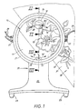
- the magnifying glass according to the invention consists of a lens combination 10, which is rotatably mounted in a frame 20. There is a combination of a large-area main lens 11 and a small auxiliary lens 12 before. These two lenses 11. 12 generate for a user of the magnifying glass, which considers a workpiece 30, mutually different magnifications, as illustrated with reference to FIG. 1.
- the workpiece 30 is a textile fabric 31 on which embroidery work 32 is to be performed.
- the main lens 11 already provides magnification, e.g. by the factor 2.
- the auxiliary lens 12 provides an even higher magnification, e.g. an 8x magnification.
- the lens combination 10 is held in a frame 20.
- This frame 20 comprises a bearing frame 21, which is connected to other frame parts 22 and supports 23.
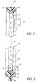
- the bearing frame 21 comprises, as can be seen from Figs. 2 and 3, the peripheral edge 25 of the lens combination 10, whereby there is a sliding bearing 25 is formed.
- the additional lens 12 is arranged eccentrically with respect to the axis of rotation 13; it is located in one of Fig. 1 with 19 marked lateral offset.
- the auxiliary lens 12 mutatis mutandis in the direction of the rotary arrows 28, 28' adjusted.
- the additional lens 12 takes the additional lens 12 a changed rotational position, which allows viewing of another area of the workpiece 30. In this case, the position of the frame 20 with respect to the viewer need not be changed.
- Fig. 1 Dotted in Fig. 1 is a diameter 24, on which both the additional lens 12 and the handle 17 is seated.
- the handle 17 with respect to the additional lens 12 on the opposite side of the rotation axis 13.
- the handle 17 is disposed in an edge region 26, which positions it as close as possible to the bearing frame 21.
- rotary handle 17 could also be designed differently. You could sit at a defined position of the frame 20 and od via a rotary gear. Like. For the rotary actuator 28, 28 'of the lens combination 10 in the bearing frame 21 provide. In this case, the handle would be a knob.
- the frame 20 may be formed in any desired manner. It may be mounted on a support or hanging from the body of the user. The latter is realized in the present case.
- the frame 20 is brought by means of the supports 23 on the body of the viewer to the plant.
- At the periphery of the bearing frame 21 there are points of attack 27 for engaging the body of the viewer holding means 29. These consist in the present case of a cord 29.
- the points of attack are formed as diametrical tabs 27 on the frame 20 and provided with holes through which the cord 29 passed is.
- the cord 29 forms a loop, which engages behind the body back of the user in use.
- the frame 20 may be provided with a lighting device. It is advisable to integrate such a lighting device in the frame part 22 and / or in the bearing frame 21.
- Fig. 4 has substantially the same structure as the magnifying glass shown in the preceding embodiment. It takes me to the Deviations to be received. Incidentally, the previous description and the previous reference numerals apply.
- a rotary handle 17 ' is no longer axially parallel, but is arranged radially to the axis of rotation of the magnifying glass.
- the bearing frame 21 is connected to the frame 20 by a transverse to the axis of rotation 13 pivot axis 35 which allows a bending of the bearing frame 21 relative to the frame 20 in an optimal position.
- a locking means 36 such as a clamping screw.
- a bracket 37 is mounted on a further pivot axis 38 on the frame 20, which can be transferred to different positions to the frame or lens combination 10.
- a provided in the axis 38 fixation 39 is used to stabilize the position.
Landscapes
- Physics & Mathematics (AREA)
- General Physics & Mathematics (AREA)
- Optics & Photonics (AREA)
- Lenses (AREA)
- Professional, Industrial, Or Sporting Protective Garments (AREA)
- Glass Compositions (AREA)
Description
- Die Erfindung richtet sich auf eine Lupe der im Oberbegriff des Anspruches 1 angegebenen Art. Um bedarfsweise eine gegenüber der Hauptlinse höhere Vergrößerung nutzen zu können, ist eine kleinere Zusatzlinse mit höherer Vergrößerung an einer außermittigen Stelle an der einen Kreisfläche der Hauptlinse befestigt. Diese Baueinheit aus Hauptlinse und Zusatzlinse soll nachfolgend kurz "Linsen-Kombination" bezeichnet werden.
- Bei der bekannten Lupe dieser Art (Firmenschrift Prym: "Universal-Lupe") war die Linsen-Kombination mit dem sie halternden Teil des Gestells starr verbunden. Das Gestell wurde am Körper des Benutzers durch Haltemittel festgelegt, wozu ein schwenkbar am Gestell angeordneter Haken diente. Dieser Haken konnte den Nacken des Benutzers umgreifen. Die Position der Linsen-Kombination konnte gegenüber den Augen des Benutzers durch eine Gelenkverbindung zwischen Gestellteil oder durch Veränderung der Abstützlage des Gestells einerseits und des Hakens am Körper des Benutzers andererseits variiert werden. Abgesehen davon, dass diese Lageänderungen des Gestells mühsam waren, ergaben sich ungünstige Positionen für die Zusatzlinse, die nicht befriedigend durch veränderte Stellungen des Kopfes oder des Werkstücks korrigiert werden konnten.
- Es ist bei einem Zweistärkenlupenglas (DE-AS 14 97 658) bekannt, auf einem sphärischen Trägerglas einen segmentförmigen Lupenteil zu befestigen. Dieses Glas ist als Sehhilfe für schwachsichtige Personen gedacht, wobei der Lupenteil in der gewünschten Lage vor dem Auge gehalten wird. Eine Drehung dieser Linsen-Kombination ist weder vorgesehen noch zulässig.
- Bei einer bifokalen Lupe anderer Art (DE-OS 21 46 043), die zum Festhalten an einem Auge bestimmt ist, wird neben einer feststehenden, unverdrehbaren Hauptlinse, eine davon getrennte Nebenlinse mit einem exzentrisch zur Hauptachse der Lupe angeordneten Schwerpunkt verwendet. Die Nebenlinse ist unabhängig von der Hauptlinse in einer Innennut der Halterung aufgenommen und kann sich unter der Einwirkung ihres Eigengewichts drehen. Gleichgültig wie man die bifokale Lupe vor das Auge setzt, rollt sich die Nebenlinse vor der Hauptlinse bis ihr Schwerpunkt die tiefste Lage in der Innennut einnimmt. Eine gemeinsame Drehung der Nebenlinse mit der Hauptlinse ist weder vorgesehen, noch sinnvoll.
- Bei einer Schutzbrille (US-A-3 544 686) ist es bekannt, Schnappringe, die als Halter für Linsen dienen, in die Brillenöffnung einzusetzen. Um das Einsetzen in die Brillenöffnung zu erleichtern, ist der Schnappring mit einem abragenden Griff versehen. Der einzusetzende Schnappring besitzt in einem ersten Fall eine Vollkreislinse und eine Halbkreislinse, die in zwei getrennten, oder in einer gemeinsamen Innennut des Schnapprings aufgenommen sind. Die Halblinse hat eine andere Vergrößerung als die volle Linse. Zur Lagesicherung der Halbkreislinse im Schnappring besitzt die Innennut radiale Vorsprünge, die eine Drehung der Halblinse im Schnappring verhindern. Alternativ kann eine einzige bifokolare Linse in einer einzelnen Innennut des Sprengrings angeordnet sein, die zwischen den beiden Linsenhälften Einschnitte aufweist. In die Einschnitte greifen radiale Vorsprünge in der Innennut ein und positionieren die bifokulare Linse drehfest im Sprengring.
- Der Erfindung liegt die Aufgabe zugrunde, eine preiswerte, zuverlässige Lupe der im Oberbegriff des Anspruches 1 angegeben Art zu entwickeln, die sich bequem den jeweiligen Arbeitsverhältnissen anpassen lässt. Dies wird erfindungsgemäß durch die im Kennzeichen des Anspruches 1 angeführten Maßnahmen erreicht, denen folgende besondere Bedeutung zukommt.
- Bei der Linsen-Kombination ist eine Hauptlinse, die einen großen Kreisdurchmesser aufweist, Träger einer kleineren Zusatzlinse, die an einer außenmittigen Stelle an der einen Kreisfläche der Hauptlinse befestigt ist. Der Kreisumfang der Hauptlinse dient zur unmittelbaren Drehlagerung der ganzen Linsen-Kombination im Rahmen eines Gestells, welches im Gebrauchsfall zur Abstützung der Linse an einer Arbeitsfläche oder an der Brust eines Benutzers genutzt wird. So ist eine Innennut im Rahmen über die Hauptlinse ein Gleitdrehlager für die ganze Linsen-Kombination. Zu ihrer Drehverstellung ist an der Hauptlinse eine Drehhandhabe angebracht. Damit lässt sich die Linsen-Kombination in eine Drehstellung bringen, wo die Zusatzlinse in die jeweils gewünschte Position gegenüber dem Werkstück gebracht werden kann. Bei Änderung des Betrachtungswinkels und/oder Lage des Werkstücks kann durch Drehung die dann gewünschte geänderte Stellung der Zusatzlinse nachjustiert werden. Weil die Einstellung der Lupe durch ihre Drehlagerung im Gestell den jeweiligen Arbeitsverhältnissen angepasst werden kann, braucht die Lage des Gestells auf der Unterlage oder an der Abstützstelle des Körpers des Benutzers nicht geändert zu werden. Es ist stets ein optimaler Gebrauch der Lupe möglich.
- Weitere Maßnahmen und Vorteile der Erfindung ergeben sich aus den Unteransprüchen, der nachfolgenden Beschreibung und den Zeichnungen. In den Zeichnungen ist die Erfindung in zwei Ausführungsbeispielen dargestellt. Es zeigen:
- Fig. 1
- die Ansicht eines ersten Ausführungsbeispiels der erfindungsgemäßen Lupe,
- Fig. 2 bzw. Fig. 3,
- in Vergrößerung, Teilquerschnitte durch die Lupe längs der Schnittlinien II - II bzw. III - III von Fig. 1 und
- Fig. 4
- in perspektivischer Ansicht eine alternative Ausführung.
- Die Lupe nach der Erfindung besteht aus einer Linsen-Kombination 10, die in einem Gestell 20 drehgelagert ist. Es liegt eine Kombination aus einer großflächigen Hauptlinse 11 und einer kleinen Zusatzlinse 12 vor. Diese beiden Linsen 11. 12 erzeugen für einen Benutzer der Lupe, der ein Werkstück 30 betrachtet, zueinander unterschiedliche Vergrößerungen, wie anhand der Fig. 1 verdeutlicht ist. Dort handelt es sich beim Werkstück 30 um ein textiles Flächengebilde 31, auf welchem Stickarbeiten 32 ausgeführt werden sollen. Die Hauptlinse 11 liefert bereits eine Vergrößerung, z.B. um den Faktor 2. Die Zusatzlinse 12 dagegen liefert eine noch höhere Vergrößerung, z.B. eine 8-fache Vergrößerung.
- Die Linsen-Kombination 10 ist in einem Gestell 20 gehaltert. Dieses Gestell 20 umfasst einen Lagerrahmen 21, der mit weiteren Gestellteilen 22 und Stützen 23 verbunden ist. Der Lagerrahmen 21 umfasst, wie aus Fig. 2 und 3 zu ersehen ist, den Umfangsrand 25 der Linsen-Kombination 10, wodurch dort ein Gleitdrehlager 25 entsteht. In diesem Fall befindet sich eine Handhabe 17 an der Schauseite 16 der Hauptlinse 11. Diese besteht im vorliegenden Fall aus einem Stift oder Knopf, der bezüglich der strichpunktiert in Fig. 3 angedeuteten Linsenebene 14 absteht und insbesondere im wesentlichen senkrecht dazu verläuft. Über diese Handhabe 17 lässt sich die Linsen-Kombination 10 bezüglich des Gestells 20 im Sinne der Pfeile 18. 18' verdrehen.
- Dadurch entsteht eine in der Mitte der Linsen-Kombination 10 liegende Drehachse 13, die senkrecht zu der vorerwähnten Linsenebene 14 verläuft. Der als Handhabe dienende Stift 17 verläuft im wesentlichen parallel dazu, also achsparallel. Die Zusatzlinse 12 ist bezüglich der Drehachse 13 außermittig angeordnet; sie befindet sich in einem aus Fig. 1 mit 19 gekennzeichneten seitlichen Versatz. Beim vorerwähnten Drehen 18, 18' wird folglich die Zusatzlinse 12 sinngemäß in Richtung der Drehpfeile 28, 28' verstellt. Bei gleichem Blickwinkel des Betrachters nimmt dann die Zusatzlinse 12 eine veränderte Drehstellung ein, die eine Betrachtung eines anderen Bereichs des Werkstücks 30 erlaubt. Dabei braucht die Position des Gestells 20 gegenüber dem Betrachter nicht verändert zu werden.
- Gepunktet in Fig. 1 ist ein Durchmesser 24, auf welchem sowohl die Zusatzlinse 12 als auch die Handhabe 17 sitzt. Dabei befindet sich die Handhabe 17 bezüglich der Zusatzlinse 12 auf der gegenüberliegenden Seite der Drehachse 13. Um ein hohes Drehmoment zu erlangen, ist die Handhabe 17 in einem Randbereich 26 angeordnet, der sie möglichst nahe an den Lagerrahmen 21 positioniert.
- Es versteht sich, dass die Drehhandhabe 17 auch anders ausgebildet sein könnte. Sie könnte an einer definierten Stelle des Gestells 20 sitzen und über ein Drehgetriebe od. dgl. für die Drehbetätigung 28, 28' der Linsen-Kombination 10 im Lagerrahmen 21 sorgen. In diesem Falle wäre die Handhabe ein Drehknopf.
- Das Gestell 20 kann in beliebiger Weise ausgebildet sein. Es kann auf einer Unterlage stehend oder hängend am Körper des Benutzers angebracht seien. Letzteres ist im vorliegenden Fall verwirklicht. Das Gestell 20 wird mittels der Stützen 23 am Körper des Betrachters zur Anlage gebracht. Am Umfangsbereich des Lagerrahmens 21 gibt es Angriffsstellen 27 für am Körper des Betrachters angreifende Haltemittel 29. Diese bestehen im vorliegenden Fall aus einer Kordel 29. Die Angriffsstellen sind als diametrale Laschen 27 am Gestell 20 ausgebildet und mit Bohrungen versehen, durch welche die Kordel 29 hindurchgeführt ist. Die Kordel 29 bildet dabei eine Schlaufe, die im Gebrauchsfall die Körperrückseite des Benutzers hintergreift.
- Bedarfsweise kann das Gestell 20 mit einer Beleuchtungseinrichtung versehen sein. Es bietet sich an, eine solche Beleuchtungseinrichtung in den Gestellteil 22 und/oder in den Lagerrahmen 21 zu integrieren.
- Die in Fig. 4 gezeigte Ausführung hat im wesentlichen den gleichen Aufbau, wie die im vorausgehenden Ausführungsbeispiel gezeigte Lupe. Es braucht ledielich auf die Abweichungen eingegangen zu werden. Im Übrigen gilt die bisherige Beschreibung und die bisherigen Bezugszeichen.
- Ein wesentlicher Unterschied besteht darin, dass eine Drehhandhabe 17' nicht mehr achsparallel, sondern radial zur Drehachse der Lupe angeordnet ist. Die Drehhandhabe 17' sitzt an der Peripherie 33 der Linsen-Kombination 10. Sie durchsetzt im vorliegenden Fall einen Schlitz 34 im Lagerrahmen 21, welcher die Drehung der Linsen-Kombination 10 begrenzen kann.
- Außerdem ist der Lagerrahmen 21 gegenüber dem Gestell 20 durch eine quer zur Drehachse 13 verlaufende Schwenkachse 35 verbunden, die eine Abwinkelung des Lagerrahmens 21 gegenüber dem Gestell 20 in eine optimale Position erlaubt. Zur Festlegung der gewünschten Winkelstellung vom Lagerrahmen 21 dient ein Feststellmittel 36, wie eine Klemmschraube. Außerdem ist am Gestell 20 ein Bügel 37 an einer weiteren Schwenkachse 38 gelagert, der in verschiedene Positionen zum Gestell bzw. zur Linsen-Kombination 10 überführt werden kann. Eine im Bereich der Achse 38 vorgesehene Fixierung 39 dient zur Lagestabilisierung.
-
- 10
- Linsen-Kombination
- 11
- großflächige Hauptlinse
- 12
- kleine Zusatzlinse
- 13
- Drehachse von 10
- 14
- Linsenebene
- 15
- Umfangsrand
- 16
- Schauseite von 11
- 17
- Handhabe, Stift (Fig. 1-3)
- 17'
- Handhabe, Stift (Fig. 4)
- 18
- Drehbewegungs-Pfeil von 17
- 18'
- Drehbewegungs-Pfeil von 17
- 19
- Versatz von 12 gegenüber 13
- 20
- Gestell
- 21
- Lagerrahmen an 20
- 22
- Gestellteile von 20
- 23
- Stütze von 20
- 24
- Durchmesser für 12/17
- 25
- Gleitdrehlager zwischen 15/21
- 26
- Randstück
- 27
- Angriffsstelle für 29 / Laschen
- 28
- Drehpfeil von 12
- 28'
- Drehpfeil von 12
- 29
- Haltemittel für 20 / Kordel
- 30
- Werkstück / Stickarbeit
- 31
- textiles Flächengebilde
- 32
- Stickarbeiten
- 33
- Peripherie von 10 (Fig. 4)
- 34
- Schlitz für 17' (Fig. 4)
- 35
- Schwenkachse (Fig. 4)
- 36
- Feststellmittel (Fig. 4)
- 37
- Bügel (Fig. 4)
- 38
- Schwenkachse (Fig. 4)
- 39
- Fixierung (Fig. 4)
Claims (10)
- Lupe zum Lesen oder für Hand- und Bastelarbeiten, mit einer Linsen-Kombination (10),
bestehend aus einer Hauptlinse (11) mit großem Kreisdurchmesser (24)
und aus einer kleineren Zusatzlinse mit höherer Vergrößerung, die an einer außermittigen Stelle (19) auf der einen Linsenoberfäche (16) der Hauptlinse (11) integriert ist,
und mit einem die Hauptlinse (11) aufnehmenden Rahmen eines Gestells (20), welches so ausgebildet ist, dass es sich im Gebrauchsfall an einer Arbeitsfläche oder an der menschlichen Brust eines Benutzers abstützt,
dadurch gekennzeichnet ,
dass der Kreisumfang der Hauptlinse (11) und ihr Rahmen (21) ein Gleitdrehlager (25) für die Linsen-Kombination (10) bildet in welchem die Linsen-Kombination (10) drehbar gelagert ist und the Drehachse der Linsen-Kombination (10) senkrecht zu ihrer Linsenebene verläuft,
und dass an der Hauptlinse (11) eine Drehhandhabe (17) sitzt, die zur Drehverstellung (18, 28) der Linsen-Kombination (10) dient. - Lupe nach Anspruch 1, dadurch gekennzeichnet, dass die Drehhandhabe (17) an der Linsen-Kombination (10) befestigt ist.
- Lupe nach Anspruch 2, dadurch gekennzeichnet, dass die Drehhandhabe (17) unmittelbar auf der Schauseite (16) der Hauptlinse (11) sitzt.
- Lupe nach Anspruch 2 oder 3, dadurch gekennzeichnet, dass die Drehhandhabe aus einem Stift (17) besteht, der im Randbereich (26) der Hauptlinse (11) sitzt und der im wesentlichen parallel zur Drehachse (13) der Linsen-Kombination (10) verläuft.
- Lupe nach Anspruch 2, dadurch gekennzeichnet, dass die Drehhandhabe (17') an der Peripherie (33) der Linsenkombination (10) sitzt.
- Lupe nach Anspruch 5, dadurch gekennzeichnet, dass die radial abstehende Drehhandhabe (17') einen Schlitz (34) im Lagerrahmen (21) durchsetzt.
- Lupe nach einem der Ansprüche 1 bis 6, dadurch gekennzeichnet, dass die Drehhandhabe (17) im wesentlichen auf einem durch die Zusatzlinse (12) gehenden Durchmesser (24) der Linsen-Kombination (10) liegt und bezüglich der Zusatzlinse (12) auf der gegenüberliegenden Seite der Drehachse (13) angeordnet ist.
- Lupe nach einem der Ansprüche 1 bis 7, dadurch gekennzeichnet, dass das Gestell (20) im Gebrauchsfall stehend auf einer Unterlage ruht.
- Lupe nach einem der Ansprüche 1 bis 7, dadurch gekennzeichnet, dass das Gestell (20) im Gebrauchsfall hängend am Körper des Benutzers positioniert ist.
- Lupe nach einem der Ansprüche 1 bis 9, dadurch gekennzeichnet, dass in das Gestell (20) eine Beleuchtungseinrichtung für ein Werkstück (30) integriert ist.
Applications Claiming Priority (3)
| Application Number | Priority Date | Filing Date | Title |
|---|---|---|---|
| DE10009360A DE10009360C2 (de) | 2000-02-29 | 2000-02-29 | Lupe mit drehbarer Linsen-Kombination |
| DE10009360 | 2000-02-29 | ||
| PCT/EP2001/001480 WO2001065298A2 (de) | 2000-02-29 | 2001-02-10 | Lupe für hand- oder bastelarbeiten, beim lesen od. dgl. |
Publications (2)
| Publication Number | Publication Date |
|---|---|
| EP1261892A2 EP1261892A2 (de) | 2002-12-04 |
| EP1261892B1 true EP1261892B1 (de) | 2006-08-16 |
Family
ID=7632710
Family Applications (1)
| Application Number | Title | Priority Date | Filing Date |
|---|---|---|---|
| EP01915220A Expired - Lifetime EP1261892B1 (de) | 2000-02-29 | 2001-02-10 | Lupe für hand- oder bastelarbeiten, beim lesen oder dergleichen |
Country Status (6)
| Country | Link |
|---|---|
| US (1) | US6717750B2 (de) |
| EP (1) | EP1261892B1 (de) |
| AT (1) | ATE336736T1 (de) |
| AU (1) | AU2001242380A1 (de) |
| DE (2) | DE10009360C2 (de) |
| WO (1) | WO2001065298A2 (de) |
Families Citing this family (8)
| Publication number | Priority date | Publication date | Assignee | Title |
|---|---|---|---|---|
| JP4072728B2 (ja) * | 2003-06-20 | 2008-04-09 | 船井電機株式会社 | 電子機器 |
| US20080158696A1 (en) * | 2006-12-28 | 2008-07-03 | Gin Fai Yip | Handheld magnifier with releasable magnifying lens |
| US20090129065A1 (en) * | 2007-11-15 | 2009-05-21 | Giora Tamir | Pen with magnifier |
| USD688289S1 (en) * | 2012-03-09 | 2013-08-20 | The Daylight Company (Holdings) Limited | Magnifier |
| US11083314B2 (en) | 2016-01-26 | 2021-08-10 | George Pietropaolo | Drinkware with lens base |
| EP4170411B1 (de) * | 2021-10-21 | 2025-01-15 | The Swatch Group Research and Development Ltd | Vergrösserungsvorrichtung mit mehrfacher vergrösserung |
| CN113900260A (zh) * | 2021-11-08 | 2022-01-07 | 张英泽 | X光片观察留存阅读器 |
| US12134847B2 (en) | 2022-08-18 | 2024-11-05 | Singer Sourcing Limited Llc | Apparatuses including support and accessory arms for positioning a sewing machine accessory |
Family Cites Families (5)
| Publication number | Priority date | Publication date | Assignee | Title |
|---|---|---|---|---|
| DE726352C (de) | 1939-09-14 | 1942-10-12 | Sendlinger Optische Glaswerke | Vergroesserungsglas |
| DE1497658B1 (de) * | 1966-09-29 | 1970-04-23 | Zeiss Carl Fa | Zweistaerkenlupenglas |
| DK124045B (da) * | 1970-09-16 | 1972-09-04 | E Ebbesen | Bifokal lup til fastholdelse ved det ene øje. |
| US5442488A (en) * | 1991-12-13 | 1995-08-15 | Pastorino; Anthony T. | Magnified mirror |
| US5754349A (en) * | 1997-01-03 | 1998-05-19 | Sunrich Manufactory Ltd. | Retractable illuminating magnifier |
-
2000
- 2000-02-29 DE DE10009360A patent/DE10009360C2/de not_active Expired - Lifetime
-
2001
- 2001-02-10 EP EP01915220A patent/EP1261892B1/de not_active Expired - Lifetime
- 2001-02-10 AT AT01915220T patent/ATE336736T1/de active
- 2001-02-10 DE DE50110749T patent/DE50110749D1/de not_active Expired - Lifetime
- 2001-02-10 AU AU2001242380A patent/AU2001242380A1/en not_active Abandoned
- 2001-02-10 US US10/182,364 patent/US6717750B2/en not_active Expired - Fee Related
- 2001-02-10 WO PCT/EP2001/001480 patent/WO2001065298A2/de not_active Ceased
Also Published As
| Publication number | Publication date |
|---|---|
| ATE336736T1 (de) | 2006-09-15 |
| DE50110749D1 (de) | 2006-09-28 |
| WO2001065298A2 (de) | 2001-09-07 |
| WO2001065298A3 (de) | 2002-03-14 |
| DE10009360A1 (de) | 2001-09-20 |
| EP1261892A2 (de) | 2002-12-04 |
| US20030011897A1 (en) | 2003-01-16 |
| AU2001242380A1 (en) | 2001-09-12 |
| DE10009360C2 (de) | 2002-01-31 |
| US6717750B2 (en) | 2004-04-06 |
Similar Documents
| Publication | Publication Date | Title |
|---|---|---|
| DE60132939T2 (de) | Elektrowerkzeug | |
| DE10321723B4 (de) | Schneidevorrichtung | |
| DE3541638C2 (de) | ||
| DE10009360C2 (de) | Lupe mit drehbarer Linsen-Kombination | |
| DE29810029U1 (de) | Thermoschrumpffilm-Schneidemechanismus für eine Etikettiermaschine | |
| DE2241785A1 (de) | Vorrichtung zum befestigen eines metallblockes an der konvexen flaeche eines brillenglases | |
| DE29912254U1 (de) | Eine verbesserte Kopflupe | |
| DE69317469T2 (de) | Brillengestell für Filtergläser | |
| DE2912613C2 (de) | Probierbrille zum Messen der Augenrefraktion | |
| EP1059553B1 (de) | Brille mit Lupen | |
| DE2701333A1 (de) | Rundschleifmaschine | |
| DE3810130C2 (de) | ||
| DE654420C (de) | Kombinierte Naeh- und Randausschlagmaschine | |
| CH630970A5 (en) | Device for aligning the orifice edge of tubular workpieces which is to be sewn | |
| DE2030620B2 (de) | Vorrichtung zur Sicherung einer Schleifscheibe gegen Überschreiten ihrer maximal zulässigen Umfangsgeschwindigkeit | |
| DE729884C (de) | Werkzeugschleif- und Laeppmaschine, insbesondere fuer Hartmetallwerkzeuge | |
| DE10222436A1 (de) | Vorrichtung zur Verbesserung des Sehvermögens und die Anwendung der Vorrichtung, besonders wenn man viel Zeit am Computer verbringt | |
| DE3509535A1 (de) | Brillenglasrandschleifmaschine | |
| DE941586C (de) | Haltevorrichtung fuer Saum- u. dgl. Zusatzapparate von Naehmaschinen | |
| DE663787C (de) | Gestell fuer Bueromaschinen | |
| DE7322347U (de) | Spulvorrichtung zum Aufspulen von Fäden, Garnen u. dgl. an Spulmaschinen | |
| AT17491B (de) | Apparat zum Schleifen von Edelsteinen. | |
| DE3743973A1 (de) | Vorrichtung zum bearbeiten zahnaerztlicher oder zahntechnischer werkstuecke | |
| DE2450379B2 (de) | Brillenfassung mit verstellbaren buegeln | |
| DE19934958A1 (de) | Befestigungsmechanismus für eine Brilleneinrichtung |
Legal Events
| Date | Code | Title | Description |
|---|---|---|---|
| PUAI | Public reference made under article 153(3) epc to a published international application that has entered the european phase |
Free format text: ORIGINAL CODE: 0009012 |
|
| 17P | Request for examination filed |
Effective date: 20020604 |
|
| AK | Designated contracting states |
Kind code of ref document: A2 Designated state(s): AT BE CH CY DE DK ES FI FR GB GR IE IT LI LU MC NL PT SE TR |
|
| AX | Request for extension of the european patent |
Free format text: AL;LT;LV;MK;RO;SI |
|
| GRAP | Despatch of communication of intention to grant a patent |
Free format text: ORIGINAL CODE: EPIDOSNIGR1 |
|
| GRAS | Grant fee paid |
Free format text: ORIGINAL CODE: EPIDOSNIGR3 |
|
| GRAA | (expected) grant |
Free format text: ORIGINAL CODE: 0009210 |
|
| AK | Designated contracting states |
Kind code of ref document: B1 Designated state(s): AT BE CH CY DE DK ES FI FR GB GR IE IT LI LU MC NL PT SE TR |
|
| PG25 | Lapsed in a contracting state [announced via postgrant information from national office to epo] |
Ref country code: IT Free format text: LAPSE BECAUSE OF FAILURE TO SUBMIT A TRANSLATION OF THE DESCRIPTION OR TO PAY THE FEE WITHIN THE PRESCRIBED TIME-LIMIT;WARNING: LAPSES OF ITALIAN PATENTS WITH EFFECTIVE DATE BEFORE 2007 MAY HAVE OCCURRED AT ANY TIME BEFORE 2007. THE CORRECT EFFECTIVE DATE MAY BE DIFFERENT FROM THE ONE RECORDED. Effective date: 20060816 Ref country code: IE Free format text: LAPSE BECAUSE OF FAILURE TO SUBMIT A TRANSLATION OF THE DESCRIPTION OR TO PAY THE FEE WITHIN THE PRESCRIBED TIME-LIMIT Effective date: 20060816 Ref country code: FI Free format text: LAPSE BECAUSE OF FAILURE TO SUBMIT A TRANSLATION OF THE DESCRIPTION OR TO PAY THE FEE WITHIN THE PRESCRIBED TIME-LIMIT Effective date: 20060816 |
|
| REG | Reference to a national code |
Ref country code: GB Ref legal event code: FG4D Free format text: NOT ENGLISH |
|
| REG | Reference to a national code |
Ref country code: CH Ref legal event code: EP Ref country code: CH Ref legal event code: NV Representative=s name: ISLER & PEDRAZZINI AG |
|
| REG | Reference to a national code |
Ref country code: IE Ref legal event code: FG4D Free format text: LANGUAGE OF EP DOCUMENT: GERMAN |
|
| REF | Corresponds to: |
Ref document number: 50110749 Country of ref document: DE Date of ref document: 20060928 Kind code of ref document: P |
|
| PG25 | Lapsed in a contracting state [announced via postgrant information from national office to epo] |
Ref country code: SE Free format text: LAPSE BECAUSE OF FAILURE TO SUBMIT A TRANSLATION OF THE DESCRIPTION OR TO PAY THE FEE WITHIN THE PRESCRIBED TIME-LIMIT Effective date: 20061116 Ref country code: DK Free format text: LAPSE BECAUSE OF FAILURE TO SUBMIT A TRANSLATION OF THE DESCRIPTION OR TO PAY THE FEE WITHIN THE PRESCRIBED TIME-LIMIT Effective date: 20061116 |
|
| PG25 | Lapsed in a contracting state [announced via postgrant information from national office to epo] |
Ref country code: ES Free format text: LAPSE BECAUSE OF FAILURE TO SUBMIT A TRANSLATION OF THE DESCRIPTION OR TO PAY THE FEE WITHIN THE PRESCRIBED TIME-LIMIT Effective date: 20061127 |
|
| GBT | Gb: translation of ep patent filed (gb section 77(6)(a)/1977) |
Effective date: 20061129 |
|
| PG25 | Lapsed in a contracting state [announced via postgrant information from national office to epo] |
Ref country code: PT Free format text: LAPSE BECAUSE OF FAILURE TO SUBMIT A TRANSLATION OF THE DESCRIPTION OR TO PAY THE FEE WITHIN THE PRESCRIBED TIME-LIMIT Effective date: 20070116 |
|
| ET | Fr: translation filed | ||
| PG25 | Lapsed in a contracting state [announced via postgrant information from national office to epo] |
Ref country code: MC Free format text: LAPSE BECAUSE OF NON-PAYMENT OF DUE FEES Effective date: 20070228 |
|
| REG | Reference to a national code |
Ref country code: IE Ref legal event code: FD4D |
|
| PLBE | No opposition filed within time limit |
Free format text: ORIGINAL CODE: 0009261 |
|
| STAA | Information on the status of an ep patent application or granted ep patent |
Free format text: STATUS: NO OPPOSITION FILED WITHIN TIME LIMIT |
|
| 26N | No opposition filed |
Effective date: 20070518 |
|
| REG | Reference to a national code |
Ref country code: CH Ref legal event code: PCAR Free format text: ISLER & PEDRAZZINI AG;POSTFACH 1772;8027 ZUERICH (CH) |
|
| PG25 | Lapsed in a contracting state [announced via postgrant information from national office to epo] |
Ref country code: GR Free format text: LAPSE BECAUSE OF FAILURE TO SUBMIT A TRANSLATION OF THE DESCRIPTION OR TO PAY THE FEE WITHIN THE PRESCRIBED TIME-LIMIT Effective date: 20061117 |
|
| PG25 | Lapsed in a contracting state [announced via postgrant information from national office to epo] |
Ref country code: CY Free format text: LAPSE BECAUSE OF FAILURE TO SUBMIT A TRANSLATION OF THE DESCRIPTION OR TO PAY THE FEE WITHIN THE PRESCRIBED TIME-LIMIT Effective date: 20060816 Ref country code: LU Free format text: LAPSE BECAUSE OF NON-PAYMENT OF DUE FEES Effective date: 20070210 |
|
| PG25 | Lapsed in a contracting state [announced via postgrant information from national office to epo] |
Ref country code: TR Free format text: LAPSE BECAUSE OF FAILURE TO SUBMIT A TRANSLATION OF THE DESCRIPTION OR TO PAY THE FEE WITHIN THE PRESCRIBED TIME-LIMIT Effective date: 20060816 |
|
| PGFP | Annual fee paid to national office [announced via postgrant information from national office to epo] |
Ref country code: CH Payment date: 20121219 Year of fee payment: 13 |
|
| PGFP | Annual fee paid to national office [announced via postgrant information from national office to epo] |
Ref country code: GB Payment date: 20121206 Year of fee payment: 13 |
|
| PGFP | Annual fee paid to national office [announced via postgrant information from national office to epo] |
Ref country code: NL Payment date: 20121112 Year of fee payment: 13 |
|
| PGFP | Annual fee paid to national office [announced via postgrant information from national office to epo] |
Ref country code: BE Payment date: 20130221 Year of fee payment: 13 |
|
| PGFP | Annual fee paid to national office [announced via postgrant information from national office to epo] |
Ref country code: AT Payment date: 20130110 Year of fee payment: 13 |
|
| BERE | Be: lapsed |
Owner name: WILLIAM *PRYM G.M.B.H. & CO. K.G. Effective date: 20140228 |
|
| REG | Reference to a national code |
Ref country code: NL Ref legal event code: V1 Effective date: 20140901 |
|
| REG | Reference to a national code |
Ref country code: CH Ref legal event code: PL |
|
| REG | Reference to a national code |
Ref country code: AT Ref legal event code: MM01 Ref document number: 336736 Country of ref document: AT Kind code of ref document: T Effective date: 20140210 |
|
| GBPC | Gb: european patent ceased through non-payment of renewal fee |
Effective date: 20140210 |
|
| PG25 | Lapsed in a contracting state [announced via postgrant information from national office to epo] |
Ref country code: LI Free format text: LAPSE BECAUSE OF NON-PAYMENT OF DUE FEES Effective date: 20140228 Ref country code: NL Free format text: LAPSE BECAUSE OF NON-PAYMENT OF DUE FEES Effective date: 20140901 Ref country code: CH Free format text: LAPSE BECAUSE OF NON-PAYMENT OF DUE FEES Effective date: 20140228 |
|
| PG25 | Lapsed in a contracting state [announced via postgrant information from national office to epo] |
Ref country code: AT Free format text: LAPSE BECAUSE OF NON-PAYMENT OF DUE FEES Effective date: 20140210 |
|
| PG25 | Lapsed in a contracting state [announced via postgrant information from national office to epo] |
Ref country code: GB Free format text: LAPSE BECAUSE OF NON-PAYMENT OF DUE FEES Effective date: 20140210 Ref country code: BE Free format text: LAPSE BECAUSE OF NON-PAYMENT OF DUE FEES Effective date: 20140228 |
|
| REG | Reference to a national code |
Ref country code: FR Ref legal event code: PLFP Year of fee payment: 16 |
|
| REG | Reference to a national code |
Ref country code: FR Ref legal event code: PLFP Year of fee payment: 17 |
|
| REG | Reference to a national code |
Ref country code: FR Ref legal event code: PLFP Year of fee payment: 18 |
|
| PGFP | Annual fee paid to national office [announced via postgrant information from national office to epo] |
Ref country code: FR Payment date: 20171220 Year of fee payment: 18 |
|
| PGFP | Annual fee paid to national office [announced via postgrant information from national office to epo] |
Ref country code: DE Payment date: 20171220 Year of fee payment: 18 |
|
| PGFP | Annual fee paid to national office [announced via postgrant information from national office to epo] |
Ref country code: IT Payment date: 20180228 Year of fee payment: 18 |
|
| REG | Reference to a national code |
Ref country code: DE Ref legal event code: R119 Ref document number: 50110749 Country of ref document: DE |
|
| PG25 | Lapsed in a contracting state [announced via postgrant information from national office to epo] |
Ref country code: DE Free format text: LAPSE BECAUSE OF NON-PAYMENT OF DUE FEES Effective date: 20190903 |
|
| PG25 | Lapsed in a contracting state [announced via postgrant information from national office to epo] |
Ref country code: FR Free format text: LAPSE BECAUSE OF NON-PAYMENT OF DUE FEES Effective date: 20190228 Ref country code: IT Free format text: LAPSE BECAUSE OF NON-PAYMENT OF DUE FEES Effective date: 20190210 |