EP1261261B1 - Pressurized writing instrument employing a compressible piston member - Google Patents
Pressurized writing instrument employing a compressible piston member Download PDFInfo
- Publication number
- EP1261261B1 EP1261261B1 EP01913308A EP01913308A EP1261261B1 EP 1261261 B1 EP1261261 B1 EP 1261261B1 EP 01913308 A EP01913308 A EP 01913308A EP 01913308 A EP01913308 A EP 01913308A EP 1261261 B1 EP1261261 B1 EP 1261261B1
- Authority
- EP
- European Patent Office
- Prior art keywords
- ink
- driving member
- ink tube
- writing
- tube
- Prior art date
- Legal status (The legal status is an assumption and is not a legal conclusion. Google has not performed a legal analysis and makes no representation as to the accuracy of the status listed.)
- Expired - Lifetime
Links
- 238000004519 manufacturing process Methods 0.000 claims description 9
- 238000000034 method Methods 0.000 claims description 9
- 238000003780 insertion Methods 0.000 claims description 7
- 230000037431 insertion Effects 0.000 claims description 7
- 230000008569 process Effects 0.000 claims description 5
- 230000006835 compression Effects 0.000 claims description 4
- 238000007906 compression Methods 0.000 claims description 4
- 239000007787 solid Substances 0.000 claims description 4
- 229920001971 elastomer Polymers 0.000 claims description 3
- 239000000806 elastomer Substances 0.000 claims description 3
- 238000000748 compression moulding Methods 0.000 claims description 2
- 239000000976 ink Substances 0.000 description 201
- 239000007789 gas Substances 0.000 description 30
- 239000000463 material Substances 0.000 description 27
- 239000004677 Nylon Substances 0.000 description 12
- 230000008901 benefit Effects 0.000 description 12
- 229920001778 nylon Polymers 0.000 description 12
- 238000007789 sealing Methods 0.000 description 10
- 239000002904 solvent Substances 0.000 description 10
- IJGRMHOSHXDMSA-UHFFFAOYSA-N Atomic nitrogen Chemical compound N#N IJGRMHOSHXDMSA-UHFFFAOYSA-N 0.000 description 4
- 230000004888 barrier function Effects 0.000 description 4
- 238000013461 design Methods 0.000 description 3
- 230000000694 effects Effects 0.000 description 3
- 230000003993 interaction Effects 0.000 description 3
- 239000000314 lubricant Substances 0.000 description 3
- 239000000126 substance Substances 0.000 description 3
- 238000009736 wetting Methods 0.000 description 3
- VEXZGXHMUGYJMC-UHFFFAOYSA-M Chloride anion Chemical compound [Cl-] VEXZGXHMUGYJMC-UHFFFAOYSA-M 0.000 description 2
- 239000004952 Polyamide Substances 0.000 description 2
- 238000010521 absorption reaction Methods 0.000 description 2
- 230000015572 biosynthetic process Effects 0.000 description 2
- 229920006351 engineering plastic Polymers 0.000 description 2
- 239000007788 liquid Substances 0.000 description 2
- 238000012423 maintenance Methods 0.000 description 2
- 229910052757 nitrogen Inorganic materials 0.000 description 2
- 229920002647 polyamide Polymers 0.000 description 2
- -1 polystryrene Polymers 0.000 description 2
- 239000000565 sealant Substances 0.000 description 2
- 230000009974 thixotropic effect Effects 0.000 description 2
- 238000012546 transfer Methods 0.000 description 2
- 229920005123 Celcon® Polymers 0.000 description 1
- 229920004943 Delrin® Polymers 0.000 description 1
- 229930182556 Polyacetal Natural products 0.000 description 1
- 229920006311 Urethane elastomer Polymers 0.000 description 1
- NIXOWILDQLNWCW-UHFFFAOYSA-N acrylic acid group Chemical group C(C=C)(=O)O NIXOWILDQLNWCW-UHFFFAOYSA-N 0.000 description 1
- 238000005452 bending Methods 0.000 description 1
- 230000008859 change Effects 0.000 description 1
- 238000006243 chemical reaction Methods 0.000 description 1
- 239000011248 coating agent Substances 0.000 description 1
- 238000000576 coating method Methods 0.000 description 1
- 238000010276 construction Methods 0.000 description 1
- 229920001577 copolymer Polymers 0.000 description 1
- 230000002939 deleterious effect Effects 0.000 description 1
- 239000013536 elastomeric material Substances 0.000 description 1
- 230000002708 enhancing effect Effects 0.000 description 1
- 238000001704 evaporation Methods 0.000 description 1
- 230000008020 evaporation Effects 0.000 description 1
- 238000000855 fermentation Methods 0.000 description 1
- 230000004151 fermentation Effects 0.000 description 1
- 239000012530 fluid Substances 0.000 description 1
- 229920001973 fluoroelastomer Polymers 0.000 description 1
- NBVXSUQYWXRMNV-UHFFFAOYSA-N fluoromethane Chemical compound FC NBVXSUQYWXRMNV-UHFFFAOYSA-N 0.000 description 1
- 229920002313 fluoropolymer Polymers 0.000 description 1
- 235000003642 hunger Nutrition 0.000 description 1
- 230000002401 inhibitory effect Effects 0.000 description 1
- 238000002347 injection Methods 0.000 description 1
- 239000007924 injection Substances 0.000 description 1
- 238000001746 injection moulding Methods 0.000 description 1
- 230000000670 limiting effect Effects 0.000 description 1
- 230000014759 maintenance of location Effects 0.000 description 1
- 230000007246 mechanism Effects 0.000 description 1
- 230000005499 meniscus Effects 0.000 description 1
- 230000005012 migration Effects 0.000 description 1
- 238000013508 migration Methods 0.000 description 1
- 230000003278 mimic effect Effects 0.000 description 1
- 239000000203 mixture Substances 0.000 description 1
- 238000000465 moulding Methods 0.000 description 1
- 229920003052 natural elastomer Polymers 0.000 description 1
- 229920001194 natural rubber Polymers 0.000 description 1
- 230000035699 permeability Effects 0.000 description 1
- 229920001084 poly(chloroprene) Polymers 0.000 description 1
- 229920002492 poly(sulfone) Polymers 0.000 description 1
- 229920000515 polycarbonate Polymers 0.000 description 1
- 239000004417 polycarbonate Substances 0.000 description 1
- 229920000728 polyester Polymers 0.000 description 1
- 229920001470 polyketone Polymers 0.000 description 1
- 229920000098 polyolefin Polymers 0.000 description 1
- 229920006124 polyolefin elastomer Polymers 0.000 description 1
- 229920006324 polyoxymethylene Polymers 0.000 description 1
- 229920002635 polyurethane Polymers 0.000 description 1
- 239000004814 polyurethane Substances 0.000 description 1
- 229920003225 polyurethane elastomer Polymers 0.000 description 1
- 230000002265 prevention Effects 0.000 description 1
- 230000002829 reductive effect Effects 0.000 description 1
- 238000009877 rendering Methods 0.000 description 1
- 230000000717 retained effect Effects 0.000 description 1
- 238000000518 rheometry Methods 0.000 description 1
- 238000000926 separation method Methods 0.000 description 1
- 229920002379 silicone rubber Polymers 0.000 description 1
- 238000003756 stirring Methods 0.000 description 1
- 238000003860 storage Methods 0.000 description 1
- 229920003051 synthetic elastomer Polymers 0.000 description 1
- 229920001169 thermoplastic Polymers 0.000 description 1
- 229920002725 thermoplastic elastomer Polymers 0.000 description 1
- 239000004416 thermosoftening plastic Substances 0.000 description 1
- 238000009423 ventilation Methods 0.000 description 1
- 229920002554 vinyl polymer Polymers 0.000 description 1
- XLYOFNOQVPJJNP-UHFFFAOYSA-N water Substances O XLYOFNOQVPJJNP-UHFFFAOYSA-N 0.000 description 1
- 238000003466 welding Methods 0.000 description 1
Images
Classifications
-
- B—PERFORMING OPERATIONS; TRANSPORTING
- B43—WRITING OR DRAWING IMPLEMENTS; BUREAU ACCESSORIES
- B43K—IMPLEMENTS FOR WRITING OR DRAWING
- B43K5/00—Pens with ink reservoirs in holders, e.g. fountain-pens
- B43K5/02—Ink reservoirs
- B43K5/06—Ink reservoirs with movable pistons for withdrawing ink from an ink-receptacle
-
- B—PERFORMING OPERATIONS; TRANSPORTING
- B43—WRITING OR DRAWING IMPLEMENTS; BUREAU ACCESSORIES
- B43K—IMPLEMENTS FOR WRITING OR DRAWING
- B43K7/00—Ball-point pens
- B43K7/02—Ink reservoirs; Ink cartridges
- B43K7/03—Ink reservoirs; Ink cartridges pressurised, e.g. by gas
Definitions
- the present invention relates generally to pressurized writing devices and more specifically to pressurized writing devices employing a compressible ink driving member.
- Pressurized writing instruments are common to the writing instrument industry and have been in use for many years. Pressurized systems have been used to minimize solvent loss in writing instruments which employ highly volatile solvents and in applications which employ high viscosity inks wherein pressure is needed to force the flow of ink to the writing tip. Moreover, the use of pressurized devices in writing instruments permits the writing instrument to be used for extended periods of time in horizontal and upside-down orientations, and has reduced the need to vigorously shake the instrument to initiate ink flow after storage in an inverted position.
- Mechanical and chemical pressurizing devices are two types of pressurizing systems which have been employed in writing instruments.
- Mechanical pressurizing devices contain a mechanism, such as a spring, to maintain constant pressure on the writing medium as the writing medium is consumed.
- Gas-pressurized systems typically use a pressurized gas, such as nitrogen, to feed ink to the point or nib of the writing instrument. Some of these devices produce a pressurized gas, such as nitrogen, through chemical reactions, fermentation, and the like. The gas maintains pressure on the writing medium for continuous supply of the medium to the point or nib of the writing instrument.
- U.S. Patent 3,130,711 to Eckerle describes writing instruments employing pressurized gas systems.
- Document US-A-3 425 779 describes a pressurized writing instrument comprising a tapered ink tube and a cylindrical piston to be used in the non-tapered part.
- Examples of commercially available writing instruments which employ pressurized gas systems include the Papermate Erasermate2 TM , produced by The Gillette Company (USA), of Boston, Massachusetts, and the Fisher Space Pen®, produced by the Fisher Space Pen Company of Boulder City, Nevada.
- an additional design consideration with respect to gas-pressurization systems is the interaction of the component containing the gas pressurization system (hereinafter the "ink tube” for the sake of simplicity) with the writing medium as well as the stability of the ink tube.
- the ink tube must be made of a material that is not gas permeable moreover, the ink tube must be able to withstand stresses during use, such as imparted by the pressurization system. Any crack in such a component will allow the gas to escape, eliminating the pressure required to feed the ink to the writing tip and thus rendering the writing instrument unusable. For this reason, nylon is often used. However, nylon is more expensive than some alternative materials.
- nylon since nylon is relatively weak, a nylon ink tube must have thick walls to withstand stresses occurring during normal use. The formation of a nylon tube with sufficiently thick walls increases material costs of an already relatively expensive ink tube. Nylon also has shrinkage and creep properties inferior to alternative materials, resulting in relatively less dimensional stability. Furthermore, nylon is somewhat hygroscopic, and generally must be dried before being molded to form the ink tube to avoid dimensional instabilities which may result from water absorption.
- the ink tube must have a relatively small cross-sectional area to ensure that the meniscus formed at the top of the ink supply prevents the pressurizing gas from flowing to the writing end of the writing instrument in the event the writing instrument is placed on its side, or turned upside-down.
- Transfer of the pressurizing gas to the writing end of the writing instrument raises the possibility of a gas pressure leak.
- such transfer may result in the creation of trapped pressurized gas bubbles within the ink supply when the writing instrument is placed in position for use. If such bubbles reach the writing ball, the gas will escape. Once insufficient gas remains in the writing instrument to force the ink to the writing tip, the writing instrument will be rendered unusable.
- a mechanical pressurization system has several advantages over a gas pressurized system. These advantages include simplification of the assembly process, greater control and regularity of the ink pressure, no risk of loss of pressurizing gas to the atmosphere, and no risk of interaction of the pressurizing gas with the components of the writing instrument.
- prior attempts to create a mechanically pressurized writing instrument have also encountered disadvantages, such as: operation being reasonable only in the vertical position (such as in U.S. Patent 4,937,594 to Niemeyer ), uneven force being applied to the ink column as the ink supply is exhausted, and added expense and complexity due to the precision required in producing an ink driving member which will fit tightly enough within the ink tube to prevent leakage past the ink driving member yet will still slide freely within the ink tube.
- an injection molded ink tube typically is tapered towards the writing tip to facilitate separation from the mold pin therein upon completion of the molding process.
- the unyielding, incompressible piston members of prior art pressurization systems cannot maintain a seal at the wider section of the ink tube yet also fit in the narrowest section to expel all ink from the writing instrument.
- a writing instrument employing a pressurizing system to feed ink to a writing tip
- a compressible ink driving member and an at least partially filled ink tube having first and second ends and an inner surface tapered toward said first end between a widest portion of said ink tube and a narrowest portion of said ink tube.
- the compressible ink driving member is capable of deforming to conform to the contours of the walls of the ink tube.
- the compressible ink driving member preferably acts as a fluid seal to prevent the writing medium from flowing past the ink driving member.
- the deformed ink driving member facilitates wiping of the writing medium from the ink tube walls.
- the compressibility of the piston member also has advantages in the manufacture and assembly process of the writing instrument by eliminating the need to manufacture precision parts with tight tolerances. Any minor variations in the size of the piston member or the ink reservoir is compensated for by the ability of the piston member to deform.
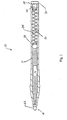
- Writing device 10 may be used independently as a writing instrument or may be formed as a cartridge for insertion into a barrel or writing implement housing.
- Writing instrument 10 generally includes an ink tube 12 partially filled with a writing medium 14 (alternately referenced herein as "ink” for the sake of convenience without intent to limit the writing medium to only ink).
- Ink tube 12 has a first end 18 and a second end 20 and an inner surface tapered toward said first end between a widest portion of said ink tube and a narrowest portion of said ink tube.
- a writing tip 22 is provided at the first end 18 of the ink tube 12.
- Writing tip 22 may be a typical ball-type writing point with a ball installed in a socket. However, any other form of writing tip may be used instead.
- writing instrument 10 is designed for a highly viscous ink.
- writing medium 14 is thixotropic.
- the tip of a ball point pen when the writing tip 22 contacts a writing surface, the tip of a ball point pen will roll, "stirring" the thixotropic writing medium near the ball and lowering its viscosity. The less viscous writing medium near the ball will then flow more freely from the tip of the pen onto the writing surface.
- the writing medium 14 may, instead, have a low viscosity, as discussed herein.
- a pressurization system 24 is provided in ink tube 12 of writing instrument 10 to pressurize writing medium 14. By pressurizing a highly viscous writing medium 14, pressurization system 24 assists in feeding the writing medium 14 out of writing tip 22.
- the pressurization system 24 comprises a pressurization device 26 and an ink driving member 28.
- writing instrument 10 includes a mechanical pressurization system 24, although any other pressurization system, such as a gas system, may be used instead.
- Pressurization system 24 of Figure 1 generally includes an ink driving member 28 driven by a pressurizing device 26, such as a spring, installed in the ink tube 12 of writing instrument 10. Pressurizing device 26 applies force to ink driving member 28, which, in turn, pressurizes writing medium 14.
- pressurizing device 26 is designed to mimic the pressure changes which occur in gas-pressurization systems.
- pressurizing device 26 may be designed to maintain a relatively constant force upon ink driving member 28. In any event pressurization system 24 must ably force to writing medium (if at a rate sufficient to keep up with the next drastic utilization of writing medium).
- Pressurization system 24 must provide sufficient force upon writing medium 14 throughout the life of writing instrument 10 to expel all of the writing medium 14 within ink tube 12 out of the writing tip 22.
- the maximum initial pressure exerted by pressurizing device 26 is selected such that ink is not driven out of writing tip 22 unintentionally.
- the force of pressurization system 24 and the rheology of the writing medium must be selected such that the driving member pushes the writing medium without being pushed into the writing medium.
- the initial force exerted by pressurizing device 26, when ink tube 12 is full of writing medium 14, may be between 550-620 kPa (80-90 psi) and preferably at least about 550 kPa (80 psi).
- pressurizing device 26 When the writing medium 14 is nearly expended, pressurizing device 26 preferably exerts a final pressure sufficient to provide a minimum force necessary to push driving member 28 to its furthest possible position within ink tube 12 to expel ink.
- the final pressure exerted by pressurizing device 26 is preferably about 100-140 kPa (15-20 psi) and at least about 70 kPa (10 psi). If pressurizing device 26 is a spring, then the spring constant and spring rate are selected to achieve the above functions.
- Pressurization system 24 must be securely retained within writing instrument 10 .
- One way of securely retaining pressurization system 24 is to provide a barrier at the back end 20 of ink tube 12 of the writing instrument to prevent pressurization system 24 from escaping from writing instrument 10.
- an end plug 30 is preferably coupled to second end 20 of ink tube 12. End plug 30 closes end 20 of ink tube 12 in order to retain the pressurization system 24 within writing instrument 10.
- end plug 30 may be shaped and configured to serve as a base and support for pressurization system 24.
- End plug 30 preferably is also shaped and configured to stabilize pressurization system 24.
- end plug 30 may be provided with a stem 40 that is shaped and configured for insertion into or affixation to pressurizing device 26. If desired, stem 40 is chamfered to facilitate insertion into the interior of the spring. End plug 30 must also be securely attached to ink tube 12 to prevent the pressurizing device 26 from forcing end plug 30 off second end 20 of ink tube 12.
- end plug 30 may be welded (e.g., by utilizing ultraelectronic welding) or e.g., attached by solvent bending to second end 20 of ink tube 12.
- a double seal as described in U.S. Patent 5,924,810 to Rukan et al. , may be used.
- the writing instrument may need to be either vented or sealed.
- end plug 30 may be provided with a vent to prevent the creation of a vacuum in the rear of the ink tube as the writing medium is expended, thereby inhibiting the entry of air bubbles into the writing medium reservoir, which may cause "starving" of writing medium to writing tip 22.
- the writing instrument must be adequately sealed so that there is no ventilation, in order to prevent evaporation of the writing medium.
- ink driving member 28 is compressible.
- the compressibility of ink driving member 28 allows deformation of ink driving member 28 when placed inside ink tube 12. This deformation compensates for any dimensional variations between ink driving member 28 and the contours of the interior of ink tube 12.
- the ability of a compressible ink driving member 28 to conform to the shape and dimensions of ink tube 12 also obviates the need to manufacture precision parts with tight tolerances for a close fit between ink driving member 28 and the interior of ink tube 12.
- a pressurizing device 28 assists in deforming ink driving member 28 as desired. Moreover, deformation of ink driving member 28 also increases the contact surface area of the portion of ink driving member 28 against the inner surface of ink tube 12. As may be appreciated, the close fit or contact between ink tube 12 and driving member 28 facilitates complete sealing of writing medium 14 within ink tube 12. Such sealing may be sufficiently tight to eliminate the need for a sealing lubricant which often has deleterious effects on the system, such as plastication of the materials thereof. The seal acts as a barrier to solvent vapor migration, as well as additional benefits.
- a compressible ink driving member 28 allows writing instrument 10 with a low viscosity to be employed in a sideways or even upside-down position, since the seal prevents backflow of writing medium 14 behind ink driving member 28.
- the close fit or contact between ink tube 10 and a compressible ink driving member 28 allows ink driving member 28 to wipe ink from the inner surface of ink tube 12 as writing medium 14 is expended and ink driving member progresses towards writing tip 22.
- the compressibility permits use of an ink driving member 28 with an outside diameter (when ink driving member 28 is not being compressed) greater than the inside diameter of ink tube 12.
- a compressible ink driving member 28 preferably has an outside diameter or dimension greater than the inside diameter or dimension of ink tube 12 and substantially conforms to the interior contours of ink tube 12 such that ink driving member 28 deforms upon insertion into ink tube 12, resulting in the advantages listed above.
- the compressibility of ink driving member 28 permits its use within the tapered ink tube 12 of varying diameter or dimension.
- the compressible ink driving member 28 is used in the ink tube 12 which tapers toward the writing end of writing instrument 10.
- ink driving member 28 is large enough to fit into and contact the inner surface 32 of ink tube 12 at the widest portion of the ink tube, yet can deform to fit into even the narrowest portion.
- the hardness, such as determined under the Shore A durometer scale (or any other scale), of ink driving member 28 is selected so that ink driving member 28 is relatively soft and pliable to permit the above-described compressibility along with the accompanying benefits of such compressibility.
- the hardness should be selected so that ink during member 28 is not prevented from deforming to fit within the inside of ink tube 12.
- a hardness of above about a Shore A durometer of 70 may create a large enough frictional force from its contact with the inner surface of ink tube 12 to inhibit advancement of the ink driving member 28 in ink tube 12 thus reducing the efficacy of pressurization system 28.
- ink driving member 28 In order to permit ink driving member 28 to be compressed and/or to deform, ink driving member 28 preferably has a hardness of less than 70. The hardness of the ink driving member 28 is not so low as to have a "gummy" texture that will not be capable of sliding as necessary within ink tube 12. Also, a very soft ink driving member 28 will inhibit the ability of ink driving member 28 to tightly seal the writing medium, since ink driving member 28 will deform easily, exerting only a low compression force onto ink tube 12. Ink driving member 28 preferably has a Shore A durometer hardness of at least about 8.
- ink driving member 28 is also solid so that it deforms uniformly under force and does not unequally absorb forces imparted thereto. Moreover, a solid member typically exerts an evenly distributed load on ink tube 12, thus improving the desired sealing effect.
- the material from which ink driving member 28 is formed also may affect the desired benefits to be imparted by ink driving member 28.
- the material should be capable of sliding within ink tube 12 and as necessary to drive the writing medium out, yet should sufficiently resist sliding movement such that the ink driving member deforms when subjected to force applied by pressurizing device 26.
- the material should allow the driving member 28 to advance the ink while also forming an effective seal against the interior of ink tube 12 and effecting the above-described wiping of ink from the interior of ink tube 12 .
- the coefficient of friction between the driving member 28 and ink tube 12 is at least 0.15 and at most 0.45.
- this coefficient of friction between these elements is less than 0.25, and must preferably within a size of almost about 0.15 to 0.25. It will be appreciated that construction of the invention is simplified because ink driving member 28 slides freely within ink tube 12 yet also provides a tight seal therein, without the use of a sealing lubricant or the need to machine the ink driving member 28 to very tight tolerances as required with conventional, non-deformable pistons.
- the material of ink driving member 28 preferably is also selected to be chemically compatible with the materials from which other components of writing instrument 10 are formed and with which ink driving member 28 may interact or contact.
- ink driving member 28 is preferably chemically compatible with at least ink tube 12 as well as with writing medium 14.
- the material of ink driving member 28 preferably is selected such that ink driving member 28 will not swell in solvents used in writing medium 14, and will not absorb solids used in writing medium 14.
- Such chemical compatibility will lend stability to ink driving member 28 since absorption of ink or ink components may change the material characteristics of the ink driving member 28, such as elasticity, elongation, tensile strength, yield strength, etc.
- ink driving member 28 preferably is resistant to wetting, particularly by writing medium 14. Most preferably, ink driving member 28 is repellant to writing medium 14 to further enhance the above-described ink-wiping effected by ink driving member 28 to provide an additional force to prevent writing medium 14 from escaping past ink driving member 28.
- the ink driving member 28 preferably has a surface tension of less than about 20 dyne-cm to inhibit wetting by writing-medium 14.
- a writing- medium-repellant coating may also be applied to the surface of ink driving member 28 to enhance the anti-wetting property of ink driving member 28.
- ink driving member 28 preferably is formed from an elastomeric material which by nature is compressible.
- a synthetic elastomer which affords more controllable characteristics than a natural elastomer, such as compressibility and ink resistance, is used.
- materials having some of the above-mentioned properties include, without limitation, silicone elastomers, neoprene elastomers, fluoroelastomers, fluorocarbon elastomers, polyolefin elastomers, urethane elastomers, and polyurethane elastomers.
- the ink driving member is formed from a thermoplastic elastomer, such as Santoprene TM . Santoprene TM is sold by Advanced Elastomer Systems, L.P., Akron, OH.
- ink tube 12 preferably is selected to be chemically compatible with the other materials of writing instrument 10.
- ink tube 12 preferably is formed from a material that is chemically compatible with writing medium 14.
- the material of ink tube 12 should provide a solvent barrier for the solvents of the volatile ink.
- the ink tube should also be gas impermeable.
- the material of ink tube 12 should be sufficiently strong and durable for its intended use.
- the ink tube 12 should not fatigue, crack, or deform during use (e.g., should withstand internal pressures generated by pressurization system 24), and preferably is environmentally stable as well as dimensionally stable at all temperatures.
- ink tube 12 is formed from a thermoplastic or thermoformable material. Nylon is typically used for gas pressurized systems since nylon not only provides the desired solvent barrier but also is gas impermeable. However, if a mechanical pressurization system, such as described above, is employed, gas permeability is irrelevant and a wider variety of materials may be used.
- Ink tube 12 may thus be formed from an engineering plastic which has the appropriate strength, rigidity, resistance to deformation, and chemical resistance to writing mediums and solvents.
- suitable materials which may be used to form an ink tube 12 in which a mechanical pressurization system is to be used include, without limitation, polyacetal, polyolefin, polyester, polyketone, polyamide, polysulfone, polystryrene, ABS, acrylic, polycarbonate, polyurethane, polyamide, cellulosics, polyvinyl, chloride (A/c), polyvinyledene chloride, fluoroplastics, and any copolymers or mixtures thereof.
- preferred engineering plastics include Celcon®, produced by Ticona, of Summit, New Jersey, or Delrin®, produced by DuPont de Nemours of Wilmington, Delaware.
- nylon typically reduces costs, since nylon is typically expensive and weak (requiring formation of an ink tube with relatively thick walls). Moreover, the above-listed materials typically have shrinkage and creep properties superior to nylon and are less hygroscopic, and thus impart greater dimensional stability to the ink tube. It is thus readily appreciated that use of a mechanical pressurization system advantageously effects the manufacture of the ink tube in which the system is to be contained.
- ink driving member 28 is selected to enhance the above-described advantages of the pressurization system 24 of the present invention.
- the ink driving member 28 is symmetrically shaped.
- ink driving member 28 preferably is spherical.
- a spherical geometry facilitates assembly of writing instrument 10, since a spherical member is completely symmetrical and thus need not be oriented in a particular direction before insertion into ink tube 12.
- the symmetrical shape ensures that the compression load exerted by ink driving member 28 will be uniformly distributed to an ink tube of typical cylindrical shape.
- the compressed surface of a spherical ink driving member has a larger contact surface than an uncompressed ink driving member, thus advantageously enhancing the above-described sealing and wiping effects.
- a cylindrically shaped ink driving member 28 would also provide ease of assembly, since it applies a substantially uniform compression load on a cylindrically shaped ink tube 12, and no particular orientation, at least about its longitudinal axis, is required.
- the writing instrument 10 is preferably manufactured by providing an ink tube 12 having a first end 18 and a second end 20.
- a writing tip 22 is preferably coupled to first end 18.
- Ink tube 12 then is filled with writing medium 14, and a pressurization system 24 including a compressible ink driving member 28 driven by pressurizing device 26, is installed in ink tube 12 thereafter.
- Manufacturing of ink driving member 28 may also be tailored to further enhance its ability to seal ink tube 12.
- ink driving member 28 preferably is formed to have a smooth surface finish for enhanced contact and sealing with ink tube 12.
- ink driving member 28 is formed by a compression molding process, and ground to its final shape to remove dimensional surface imperfections.
- a compressible ink driving member may also be used in a gas-pressurization system in accordance with the principles of the present invention, such benefits provided in a mechanical pressurization system by such an ink driving member being similarly provided to a gas-pressurization system utilizing such an ink driving member.
Landscapes
- Engineering & Computer Science (AREA)
- Mechanical Engineering (AREA)
- Pens And Brushes (AREA)
Applications Claiming Priority (3)
| Application Number | Priority Date | Filing Date | Title |
|---|---|---|---|
| US09/520,095 US6361234B1 (en) | 2000-03-08 | 2000-03-08 | Pressurized writing instrument employing a compressible piston member |
| US520095 | 2000-03-08 | ||
| PCT/US2001/006983 WO2001065970A1 (en) | 2000-03-08 | 2001-03-05 | Pressurized writing instrument employing a compressible piston member |
Publications (3)
| Publication Number | Publication Date |
|---|---|
| EP1261261A1 EP1261261A1 (en) | 2002-12-04 |
| EP1261261A4 EP1261261A4 (en) | 2007-05-23 |
| EP1261261B1 true EP1261261B1 (en) | 2009-12-23 |
Family
ID=24071171
Family Applications (1)
| Application Number | Title | Priority Date | Filing Date |
|---|---|---|---|
| EP01913308A Expired - Lifetime EP1261261B1 (en) | 2000-03-08 | 2001-03-05 | Pressurized writing instrument employing a compressible piston member |
Country Status (11)
| Country | Link |
|---|---|
| US (1) | US6361234B1 (https=) |
| EP (1) | EP1261261B1 (https=) |
| JP (1) | JP4131794B2 (https=) |
| CN (1) | CN1225369C (https=) |
| AU (1) | AU2001241985A1 (https=) |
| BR (1) | BR0109111A (https=) |
| CA (1) | CA2402333C (https=) |
| DE (1) | DE60140861D1 (https=) |
| MX (1) | MXPA02008713A (https=) |
| TW (1) | TW548202B (https=) |
| WO (1) | WO2001065970A1 (https=) |
Families Citing this family (18)
| Publication number | Priority date | Publication date | Assignee | Title |
|---|---|---|---|---|
| JP3638778B2 (ja) * | 1997-03-31 | 2005-04-13 | 株式会社ルネサステクノロジ | 半導体集積回路装置およびその製造方法 |
| WO2002055317A1 (en) * | 2001-01-10 | 2002-07-18 | Mitsubishi Pencil Kabushikikaisha | Ball-point pen refill |
| US7303351B2 (en) * | 2002-01-30 | 2007-12-04 | Mitsubishi Pencil Kabushiki Kaisha | Writing instrument and welding method of writing point assembly and writing instrument parts connecting structure and connecting method |
| US6742952B1 (en) * | 2003-02-28 | 2004-06-01 | Bic Corporation | Transparent or translucent tubular structure |
| DE102005014409B4 (de) * | 2005-03-30 | 2007-06-06 | Schwan-Stabilo Cosmetics Gmbh & Co. Kg | Auftraggerät |
| CN103565096A (zh) * | 2012-07-26 | 2014-02-12 | 黄晓倩 | 加液清洁刷 |
| US9327545B2 (en) * | 2012-10-26 | 2016-05-03 | Golf Rite Products, LLC | Handheld precise liquid marker |
| US9675788B2 (en) | 2012-10-26 | 2017-06-13 | Golf Rite Products, LLC | Handheld topical applicator |
| CN102941753A (zh) * | 2012-12-08 | 2013-02-27 | 闵锐 | 一种多功能笔 |
| CN105072950A (zh) * | 2013-03-27 | 2015-11-18 | 株式会社樱花彩色笔 | 涂敷用具 |
| CN103350586A (zh) * | 2013-07-12 | 2013-10-16 | 韶关盛怡文具有限公司 | 一种太空笔 |
| CN105966116B (zh) * | 2014-06-20 | 2017-10-10 | 刘乐凝 | 带储墨腔的笔 |
| JP6768708B2 (ja) * | 2015-12-29 | 2020-10-14 | 株式会社パイロットコーポレーション | 熱変色性筆跡を形成させるための筆記具 |
| CN113580810B (zh) | 2016-04-21 | 2023-02-24 | 米沃奇电动工具公司 | 书写工具以及制造书写工具的方法 |
| CN106240194A (zh) * | 2016-08-17 | 2016-12-21 | 韶关盛怡文具有限公司 | 新型太空笔笔芯 |
| CN109203765B (zh) * | 2018-09-14 | 2021-03-16 | 常州大学 | 一种增压式圆珠笔芯 |
| CN111086341A (zh) * | 2018-10-23 | 2020-05-01 | 张非洲 | 一种可加墨书写笔 |
| CN111489612A (zh) * | 2020-04-23 | 2020-08-04 | 濮阳职业技术学院 | 一种教育技术用教学教具 |
Family Cites Families (37)
| Publication number | Priority date | Publication date | Assignee | Title |
|---|---|---|---|---|
| US229102A (en) | 1880-06-22 | dellenbauqh | ||
| US68727A (en) | 1867-09-10 | -peter gabriel | ||
| US659925A (en) | 1899-08-31 | 1900-10-16 | Rand Mcnally & Co | Fountain-pen. |
| US1030502A (en) | 1910-10-17 | 1912-06-25 | George Heber Carter | Fountain-pen. |
| US1447495A (en) | 1920-05-13 | 1923-03-06 | Stromborg Oscar | Positive-flow fountain pen |
| US1409613A (en) | 1921-08-25 | 1922-03-14 | Strasser Robert | Fountain pen |
| US2192479A (en) | 1938-08-04 | 1940-03-05 | Jr John P Nissen | Implement for applying fluid and semipaste materials |
| US2249163A (en) | 1940-03-09 | 1941-07-15 | Jr John P Nissen | Implement for applying fluent materials |
| US2391385A (en) | 1944-09-16 | 1945-12-25 | Boral Max | Fountain pen |
| US2438786A (en) | 1945-06-07 | 1948-03-30 | Premium Merchandising Corp | Ink paste cartridge for ball point fountain pens |
| US2427069A (en) | 1945-09-28 | 1947-09-09 | Parker Pen Co | Writing instrument |
| US2557409A (en) | 1945-11-07 | 1951-06-19 | Scripto Inc | Fountain pen |
| US2426453A (en) | 1945-12-13 | 1947-08-26 | Milton Reynolds | Fountain pen |
| US2551490A (en) | 1947-01-23 | 1951-05-01 | Scripto Inc | Ball point pen |
| GB658021A (en) * | 1949-04-13 | 1951-10-03 | Edward Terrell | Improvements in or relating to fountain pens |
| NL76412C (https=) | 1949-05-23 | |||
| NL204165A (https=) | 1955-09-13 | |||
| NL113214C (https=) | 1959-02-06 | |||
| US3008476A (en) * | 1959-08-17 | 1961-11-14 | Pepin Joseph | Cosmetic applicator |
| NL266641A (https=) | 1960-07-30 | |||
| US3181539A (en) | 1961-06-12 | 1965-05-04 | Bruno D Aston | Fluent cosmetic applicator with replaceable cartridge |
| US3130711A (en) | 1961-11-22 | 1964-04-28 | Samuel Sklar | Positive pressure ball pen feed |
| US3282255A (en) | 1963-11-18 | 1966-11-01 | Donald P Killen | Pressurized ball point pen |
| US3340560A (en) | 1964-02-21 | 1967-09-12 | Platinum Pen Co Ltd | Fiber tip writing utensils |
| US3334616A (en) | 1965-10-20 | 1967-08-08 | Paper Mate Mfg Co | Ink utilization in writing instruments |
| US3425779A (en) * | 1966-09-01 | 1969-02-04 | Paul C Fisher | Pressurized marking instrument |
| US3397939A (en) | 1966-09-14 | 1968-08-20 | Carter S Ink Co | Marking instrument |
| DE1952108A1 (de) * | 1969-10-16 | 1971-04-29 | Bernhard Rehn | Kugelschreiber mit lageunabhaengiger Funktion |
| JPS50822Y1 (https=) | 1970-11-06 | 1975-01-10 | ||
| DE2355188C3 (de) * | 1972-12-20 | 1979-11-15 | Tokyo Boshi K.K., Tokio | Faserschreiberspitze |
| US4498797A (en) * | 1979-05-17 | 1985-02-12 | The Gillette Company | Pressurized cartridge for a writing instrument |
| EP0240994B2 (en) | 1986-04-10 | 1994-09-21 | Jiro Hori | Apparatus, such as pen, for applying liquid material |
| US4937594A (en) | 1988-11-07 | 1990-06-26 | Am International Corporation | Large volume pen |
| US5249875A (en) | 1990-09-11 | 1993-10-05 | Jiro Hori | Marker with pump and follower |
| US5628576A (en) * | 1995-05-08 | 1997-05-13 | Eversharp Pen Company | Pressurized refill with double seal valve core plug and a method for pressurizing a refill |
| US5738459A (en) * | 1995-05-08 | 1998-04-14 | Eversharp Pen Company | "Pressurized refill with multiple seal valve core plug and a method for pressurizing a refill" |
| US6027272A (en) * | 1998-06-19 | 2000-02-22 | The Gillette Company | Fluid delivery system |
-
2000
- 2000-03-08 US US09/520,095 patent/US6361234B1/en not_active Expired - Lifetime
-
2001
- 2001-03-05 AU AU2001241985A patent/AU2001241985A1/en not_active Abandoned
- 2001-03-05 JP JP2001564629A patent/JP4131794B2/ja not_active Expired - Fee Related
- 2001-03-05 WO PCT/US2001/006983 patent/WO2001065970A1/en not_active Ceased
- 2001-03-05 CA CA002402333A patent/CA2402333C/en not_active Expired - Fee Related
- 2001-03-05 DE DE60140861T patent/DE60140861D1/de not_active Expired - Lifetime
- 2001-03-05 CN CN01809246.2A patent/CN1225369C/zh not_active Expired - Lifetime
- 2001-03-05 EP EP01913308A patent/EP1261261B1/en not_active Expired - Lifetime
- 2001-03-05 BR BR0109111-5A patent/BR0109111A/pt not_active Application Discontinuation
- 2001-03-05 MX MXPA02008713A patent/MXPA02008713A/es active IP Right Grant
- 2001-04-16 TW TW090105412A patent/TW548202B/zh not_active IP Right Cessation
Also Published As
| Publication number | Publication date |
|---|---|
| TW548202B (en) | 2003-08-21 |
| WO2001065970A1 (en) | 2001-09-13 |
| JP4131794B2 (ja) | 2008-08-13 |
| WO2001065970A8 (en) | 2001-12-27 |
| CA2402333A1 (en) | 2001-09-13 |
| CN1225369C (zh) | 2005-11-02 |
| BR0109111A (pt) | 2003-06-03 |
| US6361234B1 (en) | 2002-03-26 |
| CN1427681A (zh) | 2003-07-02 |
| EP1261261A1 (en) | 2002-12-04 |
| CA2402333C (en) | 2007-11-13 |
| MXPA02008713A (es) | 2003-04-22 |
| AU2001241985A1 (en) | 2001-09-17 |
| EP1261261A4 (en) | 2007-05-23 |
| DE60140861D1 (de) | 2010-02-04 |
| JP2003525775A (ja) | 2003-09-02 |
Similar Documents
| Publication | Publication Date | Title |
|---|---|---|
| EP1261261B1 (en) | Pressurized writing instrument employing a compressible piston member | |
| US6454398B2 (en) | Ink cartridge for ink jet printer and method of charging ink into said cartridge | |
| US6918515B2 (en) | Liquid container | |
| US8511925B2 (en) | Liquid supply device | |
| CN101432146A (zh) | 具有防止干燥装置的滑动式书写工具 | |
| EP0936073B1 (en) | Method of charging ink into an ink cartridge | |
| KR101286908B1 (ko) | 가압 펜 | |
| KR20070058935A (ko) | 가압 펜 | |
| JP3929360B2 (ja) | 筆記具 | |
| US6435751B1 (en) | Click type writing implement | |
| JP2014144582A (ja) | 加圧式筆記具 | |
| EP1028854B1 (en) | Double seal system for pressurized writing device | |
| KR101199722B1 (ko) | 가압 펜 | |
| KR100706848B1 (ko) | 잉크 보급장치 및 잉크젯 기록장치 | |
| EP0296607A1 (en) | Multifunctional pen | |
| CN1153673C (zh) | 一种墨盒装置及其配备的单向阀体 | |
| JP4457251B2 (ja) | 塗布具及びその製造方法 | |
| JP2006123442A (ja) | 加圧式塗布具 | |
| JP4378465B2 (ja) | 塗布具 | |
| JPH0966693A (ja) | 筆記具 | |
| JP2008114399A (ja) | 液体噴射装置のキャッピングユニットおよび液体噴射装置 | |
| JPH06198901A (ja) | インクジェットプリンターのインク供給装置 | |
| JPH0558359U (ja) | 筆記具 | |
| HK1103580B (en) | Pen adapted to be pressurized | |
| HK1022668B (en) | Method of charging ink into an ink cartridge |
Legal Events
| Date | Code | Title | Description |
|---|---|---|---|
| PUAI | Public reference made under article 153(3) epc to a published international application that has entered the european phase |
Free format text: ORIGINAL CODE: 0009012 |
|
| 17P | Request for examination filed |
Effective date: 20020917 |
|
| AK | Designated contracting states |
Kind code of ref document: A1 Designated state(s): AT BE CH CY DE DK ES FI FR GB GR IE IT LI LU MC NL PT SE TR |
|
| AX | Request for extension of the european patent |
Free format text: AL;LT;LV;MK;RO;SI |
|
| RBV | Designated contracting states (corrected) |
Designated state(s): DE ES FR GB |
|
| RAP1 | Party data changed (applicant data changed or rights of an application transferred) |
Owner name: BIC CORPORATION |
|
| RIC1 | Information provided on ipc code assigned before grant |
Ipc: B43K 7/03 20060101ALI20070124BHEP Ipc: B43K 5/06 20060101AFI20070124BHEP |
|
| A4 | Supplementary search report drawn up and despatched |
Effective date: 20070419 |
|
| 17Q | First examination report despatched |
Effective date: 20071213 |
|
| GRAP | Despatch of communication of intention to grant a patent |
Free format text: ORIGINAL CODE: EPIDOSNIGR1 |
|
| GRAS | Grant fee paid |
Free format text: ORIGINAL CODE: EPIDOSNIGR3 |
|
| GRAA | (expected) grant |
Free format text: ORIGINAL CODE: 0009210 |
|
| AK | Designated contracting states |
Kind code of ref document: B1 Designated state(s): DE ES FR GB |
|
| REG | Reference to a national code |
Ref country code: GB Ref legal event code: FG4D |
|
| REF | Corresponds to: |
Ref document number: 60140861 Country of ref document: DE Date of ref document: 20100204 Kind code of ref document: P |
|
| PG25 | Lapsed in a contracting state [announced via postgrant information from national office to epo] |
Ref country code: ES Free format text: LAPSE BECAUSE OF FAILURE TO SUBMIT A TRANSLATION OF THE DESCRIPTION OR TO PAY THE FEE WITHIN THE PRESCRIBED TIME-LIMIT Effective date: 20100403 |
|
| PLBE | No opposition filed within time limit |
Free format text: ORIGINAL CODE: 0009261 |
|
| STAA | Information on the status of an ep patent application or granted ep patent |
Free format text: STATUS: NO OPPOSITION FILED WITHIN TIME LIMIT |
|
| 26N | No opposition filed |
Effective date: 20100924 |
|
| REG | Reference to a national code |
Ref country code: FR Ref legal event code: PLFP Year of fee payment: 15 |
|
| REG | Reference to a national code |
Ref country code: FR Ref legal event code: PLFP Year of fee payment: 16 |
|
| PGFP | Annual fee paid to national office [announced via postgrant information from national office to epo] |
Ref country code: GB Payment date: 20160329 Year of fee payment: 16 |
|
| PGFP | Annual fee paid to national office [announced via postgrant information from national office to epo] |
Ref country code: DE Payment date: 20160331 Year of fee payment: 16 |
|
| REG | Reference to a national code |
Ref country code: FR Ref legal event code: PLFP Year of fee payment: 17 |
|
| REG | Reference to a national code |
Ref country code: DE Ref legal event code: R119 Ref document number: 60140861 Country of ref document: DE |
|
| GBPC | Gb: european patent ceased through non-payment of renewal fee |
Effective date: 20170305 |
|
| PG25 | Lapsed in a contracting state [announced via postgrant information from national office to epo] |
Ref country code: DE Free format text: LAPSE BECAUSE OF NON-PAYMENT OF DUE FEES Effective date: 20171003 |
|
| REG | Reference to a national code |
Ref country code: FR Ref legal event code: PLFP Year of fee payment: 18 |
|
| PG25 | Lapsed in a contracting state [announced via postgrant information from national office to epo] |
Ref country code: GB Free format text: LAPSE BECAUSE OF NON-PAYMENT OF DUE FEES Effective date: 20170305 |
|
| PGFP | Annual fee paid to national office [announced via postgrant information from national office to epo] |
Ref country code: FR Payment date: 20200220 Year of fee payment: 20 |