EP1261054A2 - Régulation de la température du dispositif de combustion d'un unité de production d'énergie à pile à combustible - Google Patents
Régulation de la température du dispositif de combustion d'un unité de production d'énergie à pile à combustible Download PDFInfo
- Publication number
- EP1261054A2 EP1261054A2 EP02007652A EP02007652A EP1261054A2 EP 1261054 A2 EP1261054 A2 EP 1261054A2 EP 02007652 A EP02007652 A EP 02007652A EP 02007652 A EP02007652 A EP 02007652A EP 1261054 A2 EP1261054 A2 EP 1261054A2
- Authority
- EP
- European Patent Office
- Prior art keywords
- temperature
- combustor
- fuel
- supply amount
- fuel supply
- Prior art date
- Legal status (The legal status is an assumption and is not a legal conclusion. Google has not performed a legal analysis and makes no representation as to the accuracy of the status listed.)
- Granted
Links
Images


Classifications
-
- H—ELECTRICITY
- H01—ELECTRIC ELEMENTS
- H01M—PROCESSES OR MEANS, e.g. BATTERIES, FOR THE DIRECT CONVERSION OF CHEMICAL ENERGY INTO ELECTRICAL ENERGY
- H01M8/00—Fuel cells; Manufacture thereof
- H01M8/06—Combination of fuel cells with means for production of reactants or for treatment of residues
- H01M8/0606—Combination of fuel cells with means for production of reactants or for treatment of residues with means for production of gaseous reactants
- H01M8/0612—Combination of fuel cells with means for production of reactants or for treatment of residues with means for production of gaseous reactants from carbon-containing material
-
- Y—GENERAL TAGGING OF NEW TECHNOLOGICAL DEVELOPMENTS; GENERAL TAGGING OF CROSS-SECTIONAL TECHNOLOGIES SPANNING OVER SEVERAL SECTIONS OF THE IPC; TECHNICAL SUBJECTS COVERED BY FORMER USPC CROSS-REFERENCE ART COLLECTIONS [XRACs] AND DIGESTS
- Y02—TECHNOLOGIES OR APPLICATIONS FOR MITIGATION OR ADAPTATION AGAINST CLIMATE CHANGE
- Y02E—REDUCTION OF GREENHOUSE GAS [GHG] EMISSIONS, RELATED TO ENERGY GENERATION, TRANSMISSION OR DISTRIBUTION
- Y02E60/00—Enabling technologies; Technologies with a potential or indirect contribution to GHG emissions mitigation
- Y02E60/30—Hydrogen technology
- Y02E60/50—Fuel cells
Definitions
- This invention relates to temperature control of a combustor in a fuel cell power plant which uses reformate gas.
- Tokkai 2000-178001 and Tokkai 2000-185903 published by the Japanese Patent Office in 2000 disclose a temperature control of a vaporizer of a fuel cell power plant which uses reformate gas.
- the fuel cell power plant is provided with a fuel cell stack which generates electricity by a reaction of reformate gas, a reformer which reforms vaporized fuel and generates reformate gas, a vaporizer which vaporizes liquid fuel, and a combustor which heats the vaporizer.
- the combustor burns anode effluent discharged from the anode of the fuel cell stack, and heats the vaporizer by combustion gas.
- Supplementary fuel is also supplied to the combustor and the combustor burns the supplementary fuel together with the anode effluent to generate combustion gas.
- liquid fuel supply to the vaporizer is increased, heat required to vaporize the liquid fuel is also increased. Accordingly the supply of supplementary fuel to the combustor is increased to increase the temperature of combustion gas.
- Supplementary fuel supplied to the combustor first vaporizes by the heat of the combustor, and thereafter is burnt to generate combustion gas.
- the supply amount of the supplementary fuel is increased, the latent heat of vaporization is also increased that makes the temperature in the combustor temporarily fall.
- the combustion of the vaporized fuel thereafter raises the temperature, if the temperature by this temporary fall becomes lower than the combustion stall temperature, the combustion of the fuel in the combustor cannot be maintained.
- the temperature of the vaporizer When the temperature of the combustor falls, the temperature of the vaporizer also falls. If there is a shortfall in the power generation amount by the fuel cell stack due to the temperature fall in the vaporizer, a secondary battery discharges power in order to fill up the shortfall in power generation. As a consequence, the load on the secondary battery is increased.
- a part of the liquid fuel may be provided to the reformer without being vaporized. If the fuel in the liquid state flows into the reformer, it deteriorates the reforming performance of the reformer and increases the generation of carbon monoxide in the reformer. Carbon monoxide is known to cause the poisoning of the fuel cell stack and adversely affects the power generation performance of the fuel cell stack.
- this invention provides a fuel cell power plant, comprising a combustor which generates heat due to combustion of fuel, a vaporizer which applies heat provided from the combustor to a liquid source material and generate a vaporized source material, a fuel cell stack which generates electric power using the vaporized source material, a fuel supply device which supply fuel to the combustor, a sensor which detects a power generation requirement of the fuel cell stack, and a programmable controller.
- the programmable controller is programmed to calculate a liquid source material supply amount to the vaporizer based on the power generation requirement, calculate a fuel supply amount of the fuel supply device based on the liquid source material supply amount to the vaporizer, calculate a prediction temperature of the combustor based on the fuel supply amount of the fuel supply device, and control the fuel supply amount of the fuel supply device to prevent the prediction temperature from falling below a predetermined temperature.
- This invention also provides a control method for such a fuel cell power plant that comprises a combustor which generates heat due to combustion of fuel, a vaporizer which applies heat provided from the combustor to a liquid source material and generate a vaporized source material, a fuel cell stack which generates electric power using the vaporized source material, and a fuel supply device which supply fuel to the combustor.
- the control method comprises detecting a power generation requirement of the fuel cell stack, calculating a liquid source material supply amount to the vaporizer based on the power generation requirement, calculating the fuel supply amount of the fuel supply device based on the liquid source material supply amount to the vaporizer, calculating a prediction temperature of the combustor based on the fuel supply amount of the fuel supply device, and controlling the fuel supply amount of the fuel supply device to prevent the prediction temperature from falling below a predetermined temperature.
- FIG. 1 is a schematic diagram of a fuel cell power plant according to this invention.
- FIG. 2 is a block diagram describing the function of a controller according to this invention.
- FIGs. 3A-3C are timing charts describing a relation between an increase in a supplementary fuel supply amount to a combustor of the fuel cell power plant and a resultant temperature variation of the combustor.
- FIGs. 4A-4C are similar to FIGs. 3A-3C but showing a case where the supplementary fuel supply amount is gradually increased.
- FIGs. 5A-5C are similar to FIGs. 4A-4C but showing a case in different situation.
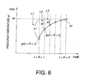
- FIG. 6 is a diagram describing a weighting coefficient ⁇ applied by the controller.
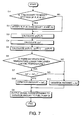
- FIG. 7 is a flowchart describing a combustor temperature control routine performed by the controller.
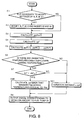
- FIG. 8 is similar to FIG. 7 but showing a second embodiment of this invention.
- a fuel cell power plant as a motive force source of a vehicle is provided with a fuel cell stack 8 which generates electricity by the reaction of hydrogen and air.
- the fuel cell stack 8 is a stack of so-called polymer electrolyte fuel cells which generate power using hydrogen-rich gas which contains a large amount of hydrogen, and air supplied from a compressor 11.
- the power generated by the fuel cell stack 8 is consumed by a load 9, such as an electric motor and a secondary battery.
- the hydrogen-rich gas is generated from methanol and water.
- the fuel cell power plant is provided with a water tank 1 and a methanol tank 2, a vaporizer 5 which vaporizes the water and methanol, a reformer 6 which generates reformate gas from the gaseous mixture of water vapor and methanol vapor, and a carbon monoxide oxidizer 7 which removes carbon monoxide (CO) from the reformate gas.
- methanol may be replaced by gasoline or any liquid material containing hydrocarbons.
- Water in the water tank 1 is supplied by a water pump 3 and methanol in the methanol tank 2 is supplied by a methanol pump 4, respectively, to the vaporizer 5, and respectively injected into the vaporizer 5 by injectors.
- the vaporizer 5 vaporizes the water and methanol using the heat generated by a combustor 10.
- the reformer 6 is known by USPat. 6, 232,005 and performs steam reforming and partial oxidation reforming of the vaporized fuel. Specifically, the reformer 6 generates hydrogen by oxidizing methanol in the presence of an oxidation catalyst. This reaction is an exothermic reaction. On the other hand, the reforming reactor 6 makes methanol react with steam to generate hydrogen. This reaction is an endothermic reaction. In both reactions, reformate gas containing hydrogen is generated from the methanol. For the oxygen supply required for partial oxidation reforming and the temperature control of the reformer 6, air is supplied to the reformer 6 from a compressor 11 via a flowrate control valve 13.
- the carbon monoxide oxidizer 7 performs catalytic combustion due to the preferential oxidation of the carbon monoxide in the reformate gas to generate hydrogen-rich gas with a low level of carbon monoxide, using noble metal catalysts such as ruthenium (Ru) and platinum (Pt).
- noble metal catalysts such as ruthenium (Ru) and platinum (Pt).
- Ru ruthenium
- Pt platinum
- the fuel cell stack 8 discharges hydrogen-containing anode effluent and oxygen-containing cathode effluent as it generates electric power.
- the anode effluent is supplied via a pressure control valve 19 and the cathode effluent is supplied via a pressure control valve 20 respectively to the combustor 10.
- the combustor 10 burns the anode effluent and supplementary fuel supplied from a fuel tank 33 via a fuel pump 34 as required in the presence of the oxygen containing cathode effluent, and supplies hot combustion gas to the vaporizer 5.
- Methanol can be used for the supplementary fuel.
- the water supply amount from the water pump 3, the methanol supply amount from the methanol pump 4, the air supply amount from the compressor 11, the power consumption amount by the load 9, the flowrate of flow control valves 13, 15, the pressures of pressure control valves 19, 20 and the fuel supply amount from a fuel pump 34, are controlled by a programmable controller 100.
- the controller 100 comprises a microcomputer provided with a central processing unit (CPU), read-only memory (ROM), random access memory (RAM) and input/output interface (I/O interface).
- the controller may also comprise two or more such microcomputers.
- the power plant is provided with the following sensors.
- These sensors comprise a flowrate sensor 14 which detects an air supply amount to the reformer 6, a flowrate sensor 16 which detects an air supply amount to the carbon monoxide oxidizer 7, a flowrate sensor 12 which detects an air supply amount of the compressor 11, a pressure sensor 17 which detects the pressure of the air supplied to the fuel cell stack 8, a pressure sensor 18 which detects the pressure of the hydrogen-rich gas supplied to the fuel cell stack 8, a temperature sensor 6A which detects the temperature of the reformer 6, a flowrate sensor 30 which detects the water supply amount from the water pump 3, a flowrate sensor 31 which detects the methanol supply amount from the methanol pump 4, a flowrate sensor 32 which detects the supplementary fuel amount supplied to the combustor 10, a temperature sensor 21 which detects the temperature of the combustion gas supplied to the vaporizer 5 from the combustor 10, an accelerator pedal depression sensor 41 which detects a depression amount of an accelerator pedal with which the vehicle is provided, and a temperature sensor 22 which detects the temperature of the combustion gas discharged in the atmosphere
- the controller 100 controls the air amount supplied to the reformer 6 and carbon monoxide oxidizer 7 from the compressor 11 by operating the flow control valves 13, 15.
- the controller 100 performs control so that the air pressure and hydrogen-rich gas pressure respectively become equal to target values suitable for power generation by operating the pressure control valves 19, 20. Since the compressor 11 supplies air to the fuel cell stack as well as to the reformer 6 and carbon monoxide oxidizer 7, controlling the air pressure supplied to the fuel cell stack 8 also means controlling the air pressure supplied to the reformer 6 and carbon monoxide oxidizer 7.
- the controller 100 also controls the air amount supplied to the fuel cell stack 8 as follows.
- the anode effluent and supplementary fuel supplied by the fuel pump 34 are burnt in the presence of the oxygen containing cathode effluent.
- the amount of the cathode effluent is determined according to the air amount supplied to the fuel cell stack 8.
- the controller 100 determines the air amount to be supplied to the fuel cell stack 8 so that the air-fuel ratio of the gaseous mixture for burning coincides with a target air-fuel ratio.
- the controller 100 also calculates the amount of water vapor and methanol vapor supplied to the reformer 6 from the methanol amount and water amount supplied to the vaporizer 5.
- the air amount required for the partial oxidation reaction of the reformer 6 and air amount required for the selective oxidation reaction of the carbon monoxide oxidizer 7 are then calculated from the amount of the water vapor and methanol vapor.
- the air amount supplied to the reformer 6 is determined based on the detection temperature of the temperature sensor 6A so that the temperature of the reformer 6 is maintained within a temperature range suitable for the reforming reaction.
- the controller 100 controls the rotation speed of the compressor 11 so that the total air supply amount detected by the flowrate sensor 12 is equal to the total air amount supplied to the reformer 6, the carbon monoxide oxidizer 7 and the fuel cell stack 8 determined in this way.
- Flow control valves 13, 15 are controlled so that the air amount requirement of the reformer 6 and carbon monoxide oxidizer 7 is satisfied.
- the controller 100 also determines target amounts of water and methanol supplied to the vaporizer 5, based on the power generation amount of the fuel cell stack 8 required by the load 9, and controls the rotation speed of the water pump 3 and methanol pump 4 so that the water amount and methanol amount detected by the flowrate sensors 30, 31 coincide with the target supply amounts.
- the controller 100 computes the electric power generation amount of the fuel cell stack 8 required by the load 9 based on the depression amount of the accelerator pedal depression amount detected by the accelerator pedal depression sensor 41, determines a target electric current consumption of the load 9 according to the depression amount of the accelerator pedal, and controls the load 9 so that the electric current consumption of the load 9 is equal to the target electric current consumption.
- the controller 100 calculates the target temperature of the combustor 10 in order that the vaporizer 5 vaporizes the target supply amount of methanol and water.
- the controller 100 further determines the target fuel supply amount to the combustor 10, and controls operation of the fuel pump 34 based on the target fuel supply amount so that this target temperature is realized.
- the controller 100 calculates the amount of anode effluent discharged from the fuel cell stack 8 from the methanol supply amount detected by the flowrate sensor 31.
- vaporizer 5 requires more heat in order to vaporize the increased methanol and water.
- a supplementary fuel supply amount to the combustor 10 is increased in order to increase the temperature of the combustor 10 which supplies this heat, the temperature of the combustor 10 will not rise promptly for the following reason.
- Supplementary fuel supplied to the combustor 10 is vaporized consuming heat of the combustor 10 and is burnt in the vaporized state.
- the latent heat of vaporization also increases and makes the temperature in the combustor temporarily fall. If the supplementary fuel supply amount is further increased to compensate for this temperature fall, the temperature of the combustor 10 falls still further and may become lower than the combustion stall temperature.
- methanol which is known to have large latent heat is used as supplementary fuel, such a temporary fall of temperature of the combustor 10 is significant.
- the controller 100 performs the following control.
- the controller 100 predicts the temperature variation in the combustor 10 based on the supplementary fuel amount supplied to the combustor 10 which is detected by the flowrate sensor 32 and the temperature of combustion gas detected by the temperature sensor 21, and controls the supplementary fuel amount supplied to the combustor 10 accordingly.
- a case where methanol supply amount to the vaporizer 5 is increased from a time t until a time t + 1 as shown in FIG. 3A is considered.
- the methanol supply amount at the time t is termed A
- the methanol supply amount at the time t + 1 is termed B
- the variation of methanol supply amount during this period is termed ⁇ u(t).
- the required heat amount of the combustor 10 also increases.
- the supplementary fuel amount supplied to the combustor 10 increases as shown by the dotted line in FIG. 3B so as to realize the new target temperature T1.
- the temperatures before the time t comprise the detected values from the temperature sensor 21 and the temperatures after the time t + 1 are the values predicted by the controller 100.
- the temperature of the combustor 10 shifts to an increasing direction.
- it reaches the target temperature T1 that is higher than the temperature T0 before the time t and stabilizes at that value thereafter.
- the temperature of the combustor will rise after the time t + 2 .
- the lower limiting temperature Tlim is a value defined according to the combustion stall temperature. If on the other hand the lowest value at the time t + 2 is lower than the lower limiting temperature Tlim as shown by the solid line in the figure, the combustor 10 may stop combustion. When such a situation is anticipated, therefore, the value of ⁇ u(t) should not be set equal to B - A at the time t .
- the controller 100 set the variation ⁇ u(t) in the following manner.
- the lowest temperature at the time t + 2 is prevented from falling below the lower limiting temperature Tlim.
- the supplementary fuel supply amount increases further at a time t + 3 when the temperature of the combustor 10 again starts to rise, but the lowest temperature that consequently appears at a time t + 5 is also prevented from falling below the lower limiting temperature Tlim.
- the temperature of the combustor 10 reaches the target temperature T1 .
- the increase in the methanol supply amount to the vaporizer 5 is performed in two phases, i.e., at the time t - 2 and the time t .
- the temperature of the combustor falls below the lower limiting temperature Tlim as shown by the arrow in FIG. 5C, if the supplementary fuel supply amount to the combustor 10 is increased from A to B and B to C synchronously with the increase of the methanol supply amount as shown in FIG. 5B.
- Tb denotes the target temperature of the combustion gas in the combustor 10 corresponding to the methanol supply amount B while Td denotes the target temperature of the combustion gas in the combustor 10 corresponding to the methanol supply amount D.
- the target supplementary fuel supply amount to be reached finally is determined such that the prediction temperatures of the combustor 10 converges to the target temperature while the increasing rate thereof is determined such that any of the prediction temperatures would not fall below the lower limiting temperature Tlim due to increase in the supplementary fuel supply amount.
- the larger the number of the prediction temperatures the higher the precision of the control. In order to lower the computation load of the controller 100, however, it is preferable to decrease the number of the prediction temperatures.
- the above-mentioned control of the supplementary fuel supply amount can be performed with five prediction temperatures from the time t + 2 through the time t + 6 . Further, if the prediction temperatures at the time t + 1 and the time t + 7 are additionally obtained, the control of the supplementary fuel supply amount can be performed with high precision.
- the number of the prediction data is represented by a parameter P and the prediction period is represented by a parameter R .
- the parameter P is an integer larger than zero, while the parameter R is an integer equal to or larger than zero.
- the time at which the prediction is performed is set to an integer t .
- the time intervals of the prediction temperatures are set to unity. To summarize the above, the temperatures from the time t + R + 1 to the time t + R + P are respectively predicted at the time t .
- the parameters P and R are set according to the operation state of the fuel cell stack 8.
- the supplementary fuel supplied just before the time t + R + P will not substantially affect to the temperature variation of the combustor 10. It is therefore possible to omit some of the estimated data for the supplementary fuel supply mount near the time t + R + P in the temperature prediction process.
- the number of data required for temperature prediction is represented by a parameter S and a parameter M.
- the parameter M represents the actual number of actual data for the supplementary fuel supply amount to the combustor 10 before the time t
- the parameter S represents the number of estimated data for the supplementary fuel supply amount to the combustor 10 after the time t .
- the parameter S may be zero or a positive integer.
- the parameter M is a positive integer which does not exceed the sum of the parameters R and P .
- the data used for temperature prediction comprise actual data for the supplementary fuel supply amount from the time t - S to the time t - 1, and estimated data for the supplementary fuel supply amount from the time t to the time t + M - 1.
- the values of the parameters S, M are also made to vary according to the operation state of the fuel cell stack 8.
- the parameters P, R and S are set to larger values while the parameter M is set to a smaller value as the required power generation amount of the fuel cell stack 8 increases.
- optimum values are preset by experiment relative to various operation states of the fuel cell stack 8, and previously stored in the memory of the controller 100.
- the controller 100 reads and applies from a table which stores the values of the parameters P, R, S, M according to the operation state of the fuel cell stack 8.
- Equation (1) can be represented by a (2)-(5) determinant.
- ⁇ uf is a predicted variation amount of the supplementary fuel supply represented by the following determinant.
- ⁇ uf [ ⁇ u ( t ), ⁇ u ( t + 1 ), ⁇ u ( t + 2 ), ⁇ , ⁇ u ( t + M-1 )] T
- Af is a model coefficient of P columns and M rows
- Ao is a model coefficient of P columns and S rows
- D is a difference
- T is a transpose of a matrix
- t is the present time
- R, P, M, S are the aforesaid parameters.
- a prediction temperature yp is expressed by a matrix of P columns and one row having the P prediction temperatures from the time t + R + 1 to the time t + P as elements.
- the measured temperature y as shown by Equation (3), can be represented by a matrix of P columns and one row having the present temperature of the combustor 10 detected by the temperature sensor 21 as elements.
- the prediction variation amount ⁇ uf can be represented by a matrix of M columns and one row having the supplementary fuel supply amounts predicted from the time t to the time t + M - 1 as elements.
- the measured variation amount ⁇ uo can be represented by a determinant having the measured supplementary fuel supply amounts from the time t - 1 to the time t - S as elements.
- the predicted variation amount ⁇ uf and measured variation amount ⁇ uo both show variation amounts each time the process is executed.
- the model coefficient Af is represented by a matrix of P columns and M rows, and it shows to what extent the prediction variation amount ⁇ uf is reflected in the prediction temperature.
- the model coefficient Ao is a matrix of P columns and S rows, and shows to what extent the measured variation amount ⁇ uo is reflected in the prediction temperature yp .
- the model coefficient Af and model coefficient Ao depend on the model parameters R, P, M, S .
- the time interval may be set in various units, but here, it is set to a hundred milliseconds which is equal to the process execution interval. Therefore, the time t + R means 0.1 ⁇ R seconds after the time t .
- the prediction variation amount ⁇ uf is required in addition to the existing variation amount ⁇ uo which is a measured value, and the measured temperature y .
- Equation (7) and (8) represents a diagonal matrix.
- Equation (6) corresponds to Equation (1) solved for ⁇ uf . More specifically, Equation (6) is set by the least square method so as to minimize the sum of differences between the target temperature sp of the combustor 10 and the prediction temperatures yp at each time from the time t + R + 1 to the time t + R + P . In other words, it is a differential form of ( sp - yp ) 2 .
- the prediction variation amount ⁇ uf can also be calculated other than by the least square method such as by the linear programming method.
- Equation (6) to calculate the prediction variation amount ⁇ uf , several parameters are required in addition to the aforesaid model coefficient Af and model coefficient Ao .
- the target temperature sp which is one of these parameters is represented by a matrix having the required temperature of the combustor 10 relative to the methanol supply amount to the vaporizer 5 as elements.
- weighting coefficient ⁇ and weighting coefficient ⁇ will be described referring to FIG. 6.
- the weighting coefficient ⁇ is represented by a diagonal matrix having ⁇ 1 to ⁇ P as elements which specify the weighting relative to the difference between the target temperature sp and prediction temperature yp .
- the coefficient ⁇ i represents a weighting relative to a difference ei between the target temperature sp and the prediction temperature yp ( t + R + i ) at the time t + R + i .
- the temperature of the combustor 10 When the supplementary fuel supply amount to the combustor 10 undergoes a large variation, the temperature of the combustor 10 also undergoes a large variation, and the detection temperature of the temperature sensor 21 can no longer follow the actual temperature variation. When this situation occurs, the reliability of the temperature measurement value decreases and the temperature control may not be performed properly.
- a weighting is applied to the difference using the weighting coefficient ⁇ so that the variation of the supplementary fuel supply amount does not exceed the tracking rate of the temperature sensor 21.
- the weighting coefficient ⁇ is determined from experiment or by a simulation and previously stored in the memory of the controller 100.
- the weighting coefficient ⁇ is represented by a diagonal matrix with ⁇ 1 to ⁇ M as elements which specify the weighting relative to the supplementary fuel supply amount variation.
- the weighting coefficient ⁇ is set to diag [ 1,0,0,...0 ]
- the prediction variation amount ⁇ uf that makes the prediction value yp ( t + R + 1 ) of the temperature at the time t + R + 1 coincide with the target temperature sp can be calculated.
- diag [ ⁇ 1, ⁇ 2, ⁇ 3,.... ⁇ P ] when ⁇ i is set to a larger value than zero, the prediction variation amount ⁇ uf that makes all the P prediction temperatures from the time t + R + 1 to the time t + R +P coincide with the target temperature sp, is calculated.
- Such a setting is also possible.
- the prediction variation amount ⁇ uf obtained by solving Equation (6) includes the variation amounts predicted from the time t to the time t + M - 1 as elements.
- this prediction variation amount ⁇ uf By substituting this prediction variation amount ⁇ uf into Equation (1), the temperature variation of the combustor 10 relative to the prediction variation amount ⁇ uf can be predicted.
- the execution interval of the routine is a hundred milliseconds as described above.
- step S1 the controller 100 determines whether or not it is necessary to modify the settings of the parameters R, P, M, S based on the operation state of the fuel cell stack 8.
- a step S2 When modifications are necessary, in a step S2, the parameters R, P, M and S are modified, and the coefficients Af, Ao are recalculated accordingly.
- the controller 100 After the processing of the step S2, the controller 100 performs processing of a step S3.
- the controller 100 skips the step S2 and performs the processing of the step S3.
- the controller 100 calculates the prediction temperature yp ( R + P ) of the combustor 10 at a time R + P when the present supplementary fuel supply amount to the combustor 10 is maintained from Equation (1). Specifically, the measured variation amount ⁇ uo and measured temperature y at the present time are substituted into Equation (1), and the prediction temperature yp ( R + P ) is calculated.
- the prediction temperature yp ( R+ P ) can be interpreted as the temperature of the combustor 10 after the variation in the temperature of combustor 10 has converged.
- a next step S4 the controller 100, using Equation (6), calculates a new prediction variation amount ⁇ uf related to the supplementary fuel supply amount from the prediction temperature yp ( R + P ) and the target temperature sp determined according to the methanol supply amount to the vaporizer 5.
- a next step S5 the controller 100 calculates the prediction temperature of the combustor 10 from the time R + 1 to the time R + P by substituting the new prediction variation amount ⁇ uf into Equation (1).
- the controller 100 determines whether or not any of the prediction temperatures calculated in the step S5 is lower than the lower limiting temperature Tlim.
- the lower limiting temperature Tlim is a value set based on the combustion stall temperature.
- the lower limiting temperature Tlim is herein set to 280 degrees centigrade.
- the controller 100 performs the processing of a step S11.
- the controller 100 When, on the other hand, any of the prediction temperatures is lower than the lower limiting value Tlim , the controller 100 performs the processing of a step S7.
- the controller compares the prediction variation amount ⁇ uf with a previous value ⁇ uf -1 that is the prediction variation amount calculated on the immediately preceding occasion when the routine was performed.
- the controller 100 performs the processing of the step S11.
- the controller 100 performs the processing of a step S8A.
- the controller 100 sets a variation amount equal to the prediction variation amount ⁇ uf . After setting the variation amount in the step S11, the controller 100 performs the processing of a step S9.
- step S8A the controller 100 set the variation amount equal to the previous value ⁇ uf -1 . After setting the variation amount in the step S8A, the controller 100 performs the processing of the step S9.
- the controller 100 outputs a signal corresponding to the variation amount to the fuel pump 34 and thereafter terminates the routine.
- this combustor temperature control routine when any of the prediction temperatures is lower than the lower limiting value Tlim and the prediction variation amount ⁇ uf is larger than the previous value ⁇ uf -1 , the previous value ⁇ uf -1 is applied for the control of the supplementary fuel supply amount. In other words, only when all the prediction temperatures are larger than the lower limiting temperature Tlim, the variation amount larger than the previous value is applied. The temperature of the combustor 10 is therefore always maintained higher than the lower limiting temperature Tlim.
- the supplementary fuel supply amount is increased to as much as possible within a range that will not cause the temperature fall of the combustor 10 below the lower limiting temperature Tlim.
- a step S8B is provided in place of the step S8A of the routine of FIG. 7.
- the controller 100 recalculates the prediction variation amount ⁇ uf such that the minimum value of the prediction temperatures is equal to the lower limiting temperature Tlim. Specifically, the target temperature sp is set equal to the lower limiting temperature Tlim and the calculation of the prediction variation amount ⁇ uf in the same way as in the step S4 is performed.
- the temperature fall due to increase in the supplementary fuel supply amount to the combustor 10 and the temperature rise due to combustion of already supplied supplementary fuel in the combustor 10 are cancelled out with each other, and the temperature of the combustor is maintained at the lower limiting temperature Tlim.
- the supplementary fuel supply amount is increased as much as possible within a range that will not cause the temperature of the combustor 10 to fall below the lower limiting temperature Tlim.
- the temperature of the combustor 10 is maintained at the lower limiting temperature T ⁇ im.
- the temperature of the combustor 10 rises to the original target temperature.
- the target temperature is set equal to the lower limiting temperature Tlim, there is a possibility that the temperature of the combustor 10 instantaneously falls below the lower limiting temperature Tlim during the control process. It is therefore preferable to set the target temperature sp to a value slightly higher than the lower limiting temperature Tlim or set the lower limiting temperature Tlim to a value slightly higher than the combustion stall temperature.
- the prediction variation amount ⁇ uf may be calculated by applying a coefficient or map that specifies the relation between the supplementary fuel supply amount to the combustor 10 and the temperature thereof. Such a coefficient or map can be obtained by performing a step response experiment that obtains a result through a step by step process.
- System identification theory is known as a method for promoting a mathematical model of a dynamic system based on measured data.
- the system identification is applied to specify the relation between the variation amount ⁇ uf of the supplementary fuel supply amount and the variation amount ⁇ ya of the temperature of the combustor 10, the following Equation (9) is obtained.
- ⁇ ya G ( s ) ⁇ ⁇ uf
- Dya temperature variation of the combustor 10
- ⁇ uf variation amount of supplementary fuel supply to the combustor 10
- G(s) transfer function.
- G ( s ) K a ⁇ s + 1
- K process gain
- a slope
- s Laplacian operator.
- Equation (6) various methods other than Equation (6) can be applied to specify the relation between the variation amount ⁇ uf of the supplementary fuel supply amount to the combustor 10 and the variation amount of the temperature thereof.
Applications Claiming Priority (2)
| Application Number | Priority Date | Filing Date | Title |
|---|---|---|---|
| JP2001157049A JP3480452B2 (ja) | 2001-05-25 | 2001-05-25 | 燃料電池システムおよびエネルギ供給システム |
| JP2001157049 | 2001-05-25 |
Publications (3)
| Publication Number | Publication Date |
|---|---|
| EP1261054A2 true EP1261054A2 (fr) | 2002-11-27 |
| EP1261054A3 EP1261054A3 (fr) | 2003-01-02 |
| EP1261054B1 EP1261054B1 (fr) | 2004-01-28 |
Family
ID=19000971
Family Applications (1)
| Application Number | Title | Priority Date | Filing Date |
|---|---|---|---|
| EP02007652A Expired - Lifetime EP1261054B1 (fr) | 2001-05-25 | 2002-04-04 | Régulation de la température du dispositif de combustion d'un unité de production d'énergie à pile à combustible |
Country Status (4)
| Country | Link |
|---|---|
| US (1) | US6777123B2 (fr) |
| EP (1) | EP1261054B1 (fr) |
| JP (1) | JP3480452B2 (fr) |
| DE (1) | DE60200187T2 (fr) |
Cited By (6)
| Publication number | Priority date | Publication date | Assignee | Title |
|---|---|---|---|---|
| WO2003081689A2 (fr) * | 2002-03-27 | 2003-10-02 | Robert Bosch Gmbh | Systeme de reformage pour une pile a combustible |
| FR2858046A1 (fr) * | 2003-07-25 | 2005-01-28 | Renault Sa | Dispositif et procede de commande d'injection d'air dans un bruleur associe a un reformeur de systeme de pile a combustible |
| EP1614167A2 (fr) * | 2003-04-04 | 2006-01-11 | Texaco Development Corporation | Systeme de regulation d'equilibre de fluide a utiliser dans un convertisseur de combustible |
| WO2008029233A1 (fr) * | 2006-08-31 | 2008-03-13 | Toyota Jidosha Kabushiki Kaisha | Système de pile à combustible |
| EP1986262A1 (fr) | 2007-04-23 | 2008-10-29 | J. Eberspächer GmbH Co. KG | Procédé de calibrage pour une commande de pile à combustible |
| AT510354A1 (de) * | 2010-08-25 | 2012-03-15 | Vaillant Group Austria Gmbh | Brennstoffzellenanlage |
Families Citing this family (16)
| Publication number | Priority date | Publication date | Assignee | Title |
|---|---|---|---|---|
| US6881508B2 (en) * | 2002-05-30 | 2005-04-19 | Plug Power, Inc. | Apparatus and method for controlling a fuel cell system |
| US6884533B2 (en) * | 2002-05-31 | 2005-04-26 | Ballard Generation Systems | Utilization based power plant control system |
| WO2004054013A2 (fr) * | 2002-07-30 | 2004-06-24 | Hyradix, Inc. | Procede de regulation par l'amont pour generateurs d'hydrogene a sortie variable |
| JP4151384B2 (ja) * | 2002-11-07 | 2008-09-17 | 日産自動車株式会社 | 燃料電池システム |
| US20040247960A1 (en) * | 2003-03-31 | 2004-12-09 | Kabushiki Kaisha Toshiba | Fuel cell system |
| JP4622313B2 (ja) * | 2003-08-26 | 2011-02-02 | トヨタ自動車株式会社 | 移動体 |
| US20080248338A1 (en) * | 2004-10-05 | 2008-10-09 | Masaya Yano | Fuel Cell and Power Generating Method |
| CN100530798C (zh) * | 2005-12-31 | 2009-08-19 | 财团法人工业技术研究院 | 燃料电池液态燃料补充控制系统与液态燃料补充控制方法 |
| US7787997B2 (en) * | 2006-04-28 | 2010-08-31 | Caterpillar | Modular electric power generation system and method of use |
| JP5305119B2 (ja) * | 2006-05-09 | 2013-10-02 | 横河電機株式会社 | 燃料電池発電監視システム |
| US8026009B2 (en) * | 2006-10-17 | 2011-09-27 | Canon Kabushiki Kaisha | Exhaust fuel diluting mechanism and fuel cell system with the exhaust fuel diluting mechanism |
| US8262752B2 (en) | 2007-12-17 | 2012-09-11 | Idatech, Llc | Systems and methods for reliable feedstock delivery at variable delivery rates |
| US20090253092A1 (en) * | 2008-04-07 | 2009-10-08 | Hunter Manufacturing Co. | Fuel cell heater |
| WO2012100241A2 (fr) * | 2011-01-23 | 2012-07-26 | Michael Gurin | Cycle d'énergie supercritique hybride ayant des pressions côté haut et côté bas découplées |
| US8720390B2 (en) * | 2011-09-19 | 2014-05-13 | Northern Technologies International Corporation | Fuel performance booster |
| JP5792666B2 (ja) * | 2012-03-12 | 2015-10-14 | アイシン精機株式会社 | 燃料電池システム |
Citations (5)
| Publication number | Priority date | Publication date | Assignee | Title |
|---|---|---|---|---|
| EP0798798A2 (fr) * | 1996-03-26 | 1997-10-01 | Toyota Jidosha Kabushiki Kaisha | Méthode et appareil pour le reformage de combustible et système de pile à combustible avec appareil de reformage incorporé dedans |
| EP0957063A1 (fr) * | 1996-11-07 | 1999-11-17 | Toyota Jidosha Kabushiki Kaisha | Appareil de fabrication d'hydrogene et d'alimentation en hydrogene et voiture electrique |
| EP1122805A2 (fr) * | 2000-02-07 | 2001-08-08 | General Motors Corporation | Procédé de fonctionnement d'un dispositif de combustion pour système de piles à combustible |
| EP1160902A2 (fr) * | 2000-05-30 | 2001-12-05 | Nissan Motor Co., Ltd. | Système de pile à combustible |
| EP1211744A2 (fr) * | 2000-12-04 | 2002-06-05 | Nissan Motor Co., Ltd. | Unité de production d'énergie à pile à combustible avec dispositif de reformage |
Family Cites Families (11)
| Publication number | Priority date | Publication date | Assignee | Title |
|---|---|---|---|---|
| JPS62278767A (ja) | 1986-05-28 | 1987-12-03 | Toshiba Corp | 燃料電池発電プラント |
| JPH0415706A (ja) | 1990-05-01 | 1992-01-21 | Toshiba Corp | モデル予測制御装置 |
| US5599638A (en) * | 1993-10-12 | 1997-02-04 | California Institute Of Technology | Aqueous liquid feed organic fuel cell using solid polymer electrolyte membrane |
| US5457625A (en) | 1994-04-13 | 1995-10-10 | The M. W. Kellogg Company | Maximizing process production rates using permanent constraints |
| US5523177A (en) * | 1994-10-12 | 1996-06-04 | Giner, Inc. | Membrane-electrode assembly for a direct methanol fuel cell |
| US5945231A (en) * | 1996-03-26 | 1999-08-31 | California Institute Of Technology | Direct liquid-feed fuel cell with membrane electrolyte and manufacturing thereof |
| US5992008A (en) * | 1998-02-10 | 1999-11-30 | California Institute Of Technology | Direct methanol feed fuel cell with reduced catalyst loading |
| JP4135243B2 (ja) | 1998-12-18 | 2008-08-20 | トヨタ自動車株式会社 | 改質器の制御装置 |
| JP4147659B2 (ja) | 1998-12-24 | 2008-09-10 | トヨタ自動車株式会社 | 改質器の制御装置 |
| JP3374108B2 (ja) | 1999-09-13 | 2003-02-04 | 株式会社日立製作所 | プロセス制御装置および方法 |
| JP2001229941A (ja) * | 2000-02-16 | 2001-08-24 | Nissan Motor Co Ltd | 燃料電池システム |
-
2001
- 2001-05-25 JP JP2001157049A patent/JP3480452B2/ja not_active Expired - Lifetime
-
2002
- 2002-04-04 EP EP02007652A patent/EP1261054B1/fr not_active Expired - Lifetime
- 2002-04-04 DE DE60200187T patent/DE60200187T2/de not_active Expired - Lifetime
- 2002-05-24 US US10/153,623 patent/US6777123B2/en not_active Expired - Lifetime
Patent Citations (5)
| Publication number | Priority date | Publication date | Assignee | Title |
|---|---|---|---|---|
| EP0798798A2 (fr) * | 1996-03-26 | 1997-10-01 | Toyota Jidosha Kabushiki Kaisha | Méthode et appareil pour le reformage de combustible et système de pile à combustible avec appareil de reformage incorporé dedans |
| EP0957063A1 (fr) * | 1996-11-07 | 1999-11-17 | Toyota Jidosha Kabushiki Kaisha | Appareil de fabrication d'hydrogene et d'alimentation en hydrogene et voiture electrique |
| EP1122805A2 (fr) * | 2000-02-07 | 2001-08-08 | General Motors Corporation | Procédé de fonctionnement d'un dispositif de combustion pour système de piles à combustible |
| EP1160902A2 (fr) * | 2000-05-30 | 2001-12-05 | Nissan Motor Co., Ltd. | Système de pile à combustible |
| EP1211744A2 (fr) * | 2000-12-04 | 2002-06-05 | Nissan Motor Co., Ltd. | Unité de production d'énergie à pile à combustible avec dispositif de reformage |
Cited By (11)
| Publication number | Priority date | Publication date | Assignee | Title |
|---|---|---|---|---|
| WO2003081689A2 (fr) * | 2002-03-27 | 2003-10-02 | Robert Bosch Gmbh | Systeme de reformage pour une pile a combustible |
| WO2003081689A3 (fr) * | 2002-03-27 | 2005-01-20 | Bosch Gmbh Robert | Systeme de reformage pour une pile a combustible |
| EP1614167A2 (fr) * | 2003-04-04 | 2006-01-11 | Texaco Development Corporation | Systeme de regulation d'equilibre de fluide a utiliser dans un convertisseur de combustible |
| EP1614167A4 (fr) * | 2003-04-04 | 2010-07-14 | Texaco Development Corp | Systeme de regulation d'equilibre de fluide a utiliser dans un convertisseur de combustible |
| FR2858046A1 (fr) * | 2003-07-25 | 2005-01-28 | Renault Sa | Dispositif et procede de commande d'injection d'air dans un bruleur associe a un reformeur de systeme de pile a combustible |
| WO2008029233A1 (fr) * | 2006-08-31 | 2008-03-13 | Toyota Jidosha Kabushiki Kaisha | Système de pile à combustible |
| US8808935B2 (en) | 2006-08-31 | 2014-08-19 | Toyota Jidosha Kabushiki Kaisha | Fuel cell system |
| EP1986262A1 (fr) | 2007-04-23 | 2008-10-29 | J. Eberspächer GmbH Co. KG | Procédé de calibrage pour une commande de pile à combustible |
| AT510354A1 (de) * | 2010-08-25 | 2012-03-15 | Vaillant Group Austria Gmbh | Brennstoffzellenanlage |
| EP2424021A3 (fr) * | 2010-08-25 | 2014-03-05 | Vaillant GmbH | Système de pile à combustible |
| AT510354B1 (de) * | 2010-08-25 | 2014-06-15 | Vaillant Group Austria Gmbh | Brennstoffzellenanlage |
Also Published As
| Publication number | Publication date |
|---|---|
| EP1261054A3 (fr) | 2003-01-02 |
| EP1261054B1 (fr) | 2004-01-28 |
| JP2002352823A (ja) | 2002-12-06 |
| DE60200187D1 (de) | 2004-03-04 |
| US20020182460A1 (en) | 2002-12-05 |
| DE60200187T2 (de) | 2004-12-02 |
| JP3480452B2 (ja) | 2003-12-22 |
| US6777123B2 (en) | 2004-08-17 |
Similar Documents
| Publication | Publication Date | Title |
|---|---|---|
| EP1261054B1 (fr) | Régulation de la température du dispositif de combustion d'un unité de production d'énergie à pile à combustible | |
| US6777122B2 (en) | Vaporizer temperature control in fuel cell power plant | |
| KR100466381B1 (ko) | 연료 개질 시스템 | |
| JP2001043880A (ja) | 燃料電池スタックの監視及びシステム制御 | |
| JP2000053403A (ja) | 改質器の制御装置 | |
| US20060191202A1 (en) | Fuel reforming system | |
| US8349505B2 (en) | Power generation system of fuel cell and control method thereof | |
| US6630109B2 (en) | Control apparatus for reformer and method of controlling reformer using control apparatus | |
| US6613465B2 (en) | Control device for a fuel reforming apparatus | |
| US20020081470A1 (en) | Control method for heating processing system | |
| US6794072B2 (en) | Fuel cell system | |
| JP5263292B2 (ja) | 燃料電池システム、および、燃料電池システムの制御方法 | |
| US6607855B2 (en) | Control system for fuel cell | |
| KR101335879B1 (ko) | 연료 전지 시스템, 연료 전지 시스템의 제어 방법, 및 연료 전지의 상태 검출 방법 | |
| JP5002025B2 (ja) | 燃料改質システムおよび燃料改質システムの制御方法 | |
| JP4164901B2 (ja) | 改質器の制御装置 | |
| US7666533B2 (en) | Determination of the lambda value of reformate | |
| JP4135243B2 (ja) | 改質器の制御装置 | |
| JP3882550B2 (ja) | 移動体用燃料改質システムの制御装置 | |
| JP2000154002A (ja) | 改質ガス中の一酸化炭素濃度低減装置 | |
| JP5389716B2 (ja) | 燃料電池システム | |
| CA2615673C (fr) | Dispositif de regulation pour reformeur et methode de regulation du reformeur au moyen de ce dispositif | |
| JP2007048490A (ja) | 燃料電池システム | |
| JP2001338659A (ja) | 燃料電池システムおよび改質器の温度制御方法 | |
| JP2004232894A (ja) | 蒸発器及び改質型燃料電池システム |
Legal Events
| Date | Code | Title | Description |
|---|---|---|---|
| PUAI | Public reference made under article 153(3) epc to a published international application that has entered the european phase |
Free format text: ORIGINAL CODE: 0009012 |
|
| PUAL | Search report despatched |
Free format text: ORIGINAL CODE: 0009013 |
|
| 17P | Request for examination filed |
Effective date: 20020404 |
|
| AK | Designated contracting states |
Kind code of ref document: A2 Designated state(s): AT BE CH CY DE DK ES FI FR GB GR IE IT LI LU MC NL PT SE TR |
|
| AX | Request for extension of the european patent |
Free format text: AL;LT;LV;MK;RO;SI |
|
| AK | Designated contracting states |
Kind code of ref document: A3 Designated state(s): AT BE CH CY DE DK ES FI FR GB GR IE IT LI LU MC NL PT SE TR |
|
| AX | Request for extension of the european patent |
Free format text: AL;LT;LV;MK;RO;SI |
|
| 17Q | First examination report despatched |
Effective date: 20030221 |
|
| GRAP | Despatch of communication of intention to grant a patent |
Free format text: ORIGINAL CODE: EPIDOSNIGR1 |
|
| AKX | Designation fees paid |
Designated state(s): DE FR GB |
|
| GRAS | Grant fee paid |
Free format text: ORIGINAL CODE: EPIDOSNIGR3 |
|
| GRAA | (expected) grant |
Free format text: ORIGINAL CODE: 0009210 |
|
| AK | Designated contracting states |
Kind code of ref document: B1 Designated state(s): DE FR GB |
|
| REG | Reference to a national code |
Ref country code: GB Ref legal event code: FG4D |
|
| REG | Reference to a national code |
Ref country code: IE Ref legal event code: FG4D |
|
| REF | Corresponds to: |
Ref document number: 60200187 Country of ref document: DE Date of ref document: 20040304 Kind code of ref document: P |
|
| ET | Fr: translation filed | ||
| PLBE | No opposition filed within time limit |
Free format text: ORIGINAL CODE: 0009261 |
|
| STAA | Information on the status of an ep patent application or granted ep patent |
Free format text: STATUS: NO OPPOSITION FILED WITHIN TIME LIMIT |
|
| 26N | No opposition filed |
Effective date: 20041029 |
|
| REG | Reference to a national code |
Ref country code: IE Ref legal event code: MM4A |
|
| REG | Reference to a national code |
Ref country code: FR Ref legal event code: PLFP Year of fee payment: 15 |
|
| REG | Reference to a national code |
Ref country code: FR Ref legal event code: PLFP Year of fee payment: 16 |
|
| REG | Reference to a national code |
Ref country code: FR Ref legal event code: PLFP Year of fee payment: 17 |
|
| PGFP | Annual fee paid to national office [announced via postgrant information from national office to epo] |
Ref country code: FR Payment date: 20210210 Year of fee payment: 20 |
|
| PGFP | Annual fee paid to national office [announced via postgrant information from national office to epo] |
Ref country code: GB Payment date: 20210317 Year of fee payment: 20 |
|
| PGFP | Annual fee paid to national office [announced via postgrant information from national office to epo] |
Ref country code: DE Payment date: 20210316 Year of fee payment: 20 |
|
| REG | Reference to a national code |
Ref country code: DE Ref legal event code: R071 Ref document number: 60200187 Country of ref document: DE |
|
| REG | Reference to a national code |
Ref country code: GB Ref legal event code: PE20 Expiry date: 20220403 |
|
| PG25 | Lapsed in a contracting state [announced via postgrant information from national office to epo] |
Ref country code: GB Free format text: LAPSE BECAUSE OF EXPIRATION OF PROTECTION Effective date: 20220403 |