EP1260158B2 - Möbelschublade - Google Patents
Möbelschublade Download PDFInfo
- Publication number
- EP1260158B2 EP1260158B2 EP02007955A EP02007955A EP1260158B2 EP 1260158 B2 EP1260158 B2 EP 1260158B2 EP 02007955 A EP02007955 A EP 02007955A EP 02007955 A EP02007955 A EP 02007955A EP 1260158 B2 EP1260158 B2 EP 1260158B2
- Authority
- EP
- European Patent Office
- Prior art keywords
- drawer
- furniture
- chargeable
- storage means
- current storage
- Prior art date
- Legal status (The legal status is an assumption and is not a legal conclusion. Google has not performed a legal analysis and makes no representation as to the accuracy of the status listed.)
- Expired - Lifetime
Links
Images



Classifications
-
- F—MECHANICAL ENGINEERING; LIGHTING; HEATING; WEAPONS; BLASTING
- F21—LIGHTING
- F21V—FUNCTIONAL FEATURES OR DETAILS OF LIGHTING DEVICES OR SYSTEMS THEREOF; STRUCTURAL COMBINATIONS OF LIGHTING DEVICES WITH OTHER ARTICLES, NOT OTHERWISE PROVIDED FOR
- F21V33/00—Structural combinations of lighting devices with other articles, not otherwise provided for
- F21V33/0004—Personal or domestic articles
- F21V33/0012—Furniture
-
- A—HUMAN NECESSITIES
- A47—FURNITURE; DOMESTIC ARTICLES OR APPLIANCES; COFFEE MILLS; SPICE MILLS; SUCTION CLEANERS IN GENERAL
- A47B—TABLES; DESKS; OFFICE FURNITURE; CABINETS; DRAWERS; GENERAL DETAILS OF FURNITURE
- A47B77/00—Kitchen cabinets
- A47B77/04—Provision for particular uses of compartments or other parts ; Compartments moving up and down, revolving parts
- A47B77/08—Provision for particular uses of compartments or other parts ; Compartments moving up and down, revolving parts for incorporating apparatus operated by power, including water power; for incorporating apparatus for cooking, cooling, or laundry purposes
-
- A—HUMAN NECESSITIES
- A47—FURNITURE; DOMESTIC ARTICLES OR APPLIANCES; COFFEE MILLS; SPICE MILLS; SUCTION CLEANERS IN GENERAL
- A47B—TABLES; DESKS; OFFICE FURNITURE; CABINETS; DRAWERS; GENERAL DETAILS OF FURNITURE
- A47B88/00—Drawers for tables, cabinets or like furniture; Guides for drawers
- A47B88/90—Constructional details of drawers
-
- F—MECHANICAL ENGINEERING; LIGHTING; HEATING; WEAPONS; BLASTING
- F21—LIGHTING
- F21S—NON-PORTABLE LIGHTING DEVICES; SYSTEMS THEREOF; VEHICLE LIGHTING DEVICES SPECIALLY ADAPTED FOR VEHICLE EXTERIORS
- F21S9/00—Lighting devices with a built-in power supply; Systems employing lighting devices with a built-in power supply
- F21S9/02—Lighting devices with a built-in power supply; Systems employing lighting devices with a built-in power supply the power supply being a battery or accumulator
- F21S9/03—Lighting devices with a built-in power supply; Systems employing lighting devices with a built-in power supply the power supply being a battery or accumulator rechargeable by exposure to light
- F21S9/037—Lighting devices with a built-in power supply; Systems employing lighting devices with a built-in power supply the power supply being a battery or accumulator rechargeable by exposure to light the solar unit and the lighting unit being located within or on the same housing
-
- F—MECHANICAL ENGINEERING; LIGHTING; HEATING; WEAPONS; BLASTING
- F21—LIGHTING
- F21V—FUNCTIONAL FEATURES OR DETAILS OF LIGHTING DEVICES OR SYSTEMS THEREOF; STRUCTURAL COMBINATIONS OF LIGHTING DEVICES WITH OTHER ARTICLES, NOT OTHERWISE PROVIDED FOR
- F21V23/00—Arrangement of electric circuit elements in or on lighting devices
- F21V23/02—Arrangement of electric circuit elements in or on lighting devices the elements being transformers, impedances or power supply units, e.g. a transformer with a rectifier
-
- F—MECHANICAL ENGINEERING; LIGHTING; HEATING; WEAPONS; BLASTING
- F21—LIGHTING
- F21V—FUNCTIONAL FEATURES OR DETAILS OF LIGHTING DEVICES OR SYSTEMS THEREOF; STRUCTURAL COMBINATIONS OF LIGHTING DEVICES WITH OTHER ARTICLES, NOT OTHERWISE PROVIDED FOR
- F21V23/00—Arrangement of electric circuit elements in or on lighting devices
- F21V23/04—Arrangement of electric circuit elements in or on lighting devices the elements being switches
-
- A—HUMAN NECESSITIES
- A47—FURNITURE; DOMESTIC ARTICLES OR APPLIANCES; COFFEE MILLS; SPICE MILLS; SUCTION CLEANERS IN GENERAL
- A47B—TABLES; DESKS; OFFICE FURNITURE; CABINETS; DRAWERS; GENERAL DETAILS OF FURNITURE
- A47B2200/00—General construction of tables or desks
- A47B2200/008—Tables or desks having means for applying electronic or electric devices
- A47B2200/0083—Cable or current inlet for drawer or shelf
-
- A—HUMAN NECESSITIES
- A47—FURNITURE; DOMESTIC ARTICLES OR APPLIANCES; COFFEE MILLS; SPICE MILLS; SUCTION CLEANERS IN GENERAL
- A47B—TABLES; DESKS; OFFICE FURNITURE; CABINETS; DRAWERS; GENERAL DETAILS OF FURNITURE
- A47B2220/00—General furniture construction, e.g. fittings
- A47B2220/0075—Lighting
- A47B2220/0077—Lighting for furniture, e.g. cupboards and racks
-
- F—MECHANICAL ENGINEERING; LIGHTING; HEATING; WEAPONS; BLASTING
- F21—LIGHTING
- F21W—INDEXING SCHEME ASSOCIATED WITH SUBCLASSES F21K, F21L, F21S and F21V, RELATING TO USES OR APPLICATIONS OF LIGHTING DEVICES OR SYSTEMS
- F21W2131/00—Use or application of lighting devices or systems not provided for in codes F21W2102/00-F21W2121/00
- F21W2131/30—Lighting for domestic or personal use
- F21W2131/301—Lighting for domestic or personal use for furniture
Definitions
- the invention relates to a furniture drawer, with the features of the preamble of claim 1 and a piece of furniture with at least one such pull-out furniture drawer.
- a furniture drawer which is characterized by the features of the characterizing part of claim 1.
- the drawer or therein electrical appliances preferably household appliances
- an autonomous power supply preferably only when the drawer is closed, an electrical energy transfer for charging the rechargeable power storage.
- the charged power stores can then supply electrical consumers, such as, for example, lamps or drive motors, or they can be removed from the drawer and charged with the drawer closed.
- a non-contact transmitter preferably an inductive coupler or a plug contact
- the power supply takes place, for example, from the usual AC power supply via a transformer, which preferably produces below 25 volts in the area of the drawer, a harmless low-voltage range for humans.
- the said electrical inductive transformers are already known, for example in electric toothbrushes, and therefore need not be described in detail.
- the rechargeable power storage units are conveniently installed or integrated in the drawer wall or in the drawer bottom.
- a particularly advantageous embodiment of the invention results from the fact that at least one light source is designed as a light emitting diode (LED).
- LED light emitting diode
- Light-emitting diodes combine a compact design with a good light output with low power consumption.
- a solar cell is provided on the drawer or on the furniture carcass.
- a power supply of electrical loads in or on the drawer possible, with a rechargeable power storage is provided, which is charged via the solar cell and a corresponding charge controller.
- At least one power storage is a rechargeable battery.
- Such rechargeable batteries are available in many different embodiments, so that a suitable rechargeable battery can be selected depending on the anticipated power requirements and the available space.
- a further advantageous embodiment of the invention results from the fact that at least one rechargeable power storage is a capacitor. Even after prolonged use, there is almost no decrease in the storage capacity of a capacitor since, e.g. unlike accumulators, memory memory-reducing memory effects do not occur.
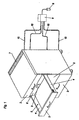
- the in Fig. 1 illustrated furniture body 1 has four pull-out drawers 2, each having a rechargeable battery (rechargeable battery) in the back wall.
- a schematically illustrated illumination 5 in practice, for example, an elongated fluorescent tube
- the power supply of this lamp 5 takes place from the rechargeable battery 3, which, as already mentioned, is integrated in the drawer rear wall 6.
- a device described in more detail below for the transmission of electrical energy is provided with a closed drawer. This energy can be done for example from solar cells 7 on top of the furniture body or a plug 8, a transformer 9 and lines 10 from the usual power grid.
- the lines inside the furniture body and between the rechargeable battery and the lamp 5 are not shown in detail. They can be laid in a space-saving and preferably invisible way. Even switches that turn on the lights only when the drawer is pulled out, are not shown in detail. For example, they may be attached to the drawer rear panel and, similar to opening a refrigerator door, turn on the lights.
- the supply via the solar cell 7 or the public power grid can be provided alternatively or simultaneously, with a not-shown electronics in the lack of light for the solar cell uses the public power grid. This can save energy. With low electrical consumption, however, the solar cell alone can be sufficient.
- the rechargeable battery 3 is integrated in the drawer bottom 11.
- the device for transmitting electrical energy here consists of a two-part inductive coupler 12a, 12b, which allows an electric power transmission when the drawer is closed and thus can charge the battery via the line 13.
- the power supply from the outside via the line 10 for example, from the public power grid, a transformer or a solar cell.
- the inductive coupler itself allows a contactless electrical transmission and, as already mentioned, for example, in electric toothbrushes already known. It is absolutely wear-resistant even with multiple opening and closing of the drawer. With the drawer pulled out, as in Fig. 2 , the drawer is disconnected from the line 10.
- the power supply of consumers not shown here, such as lamps, drive motors or the like, then takes place via the charged battery. 3
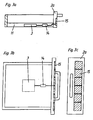
- a battery 3 is also provided in the bottom 11 of the drawer, which is chargeable via a charge controller 14 of a solar cell panel 15 on the front panel 2a of the drawer.
- an elongated fluorescent tube 5 is installed in the top frame 4a ', the walls 16 of the top frame can be made transparent at least on the inside of the drawer to illuminate the interior of the drawer can.
- the walls 16 are profiled and hold together over their profiled sections, wherein a holding part, for example made of aluminum, is provided in the upper region, which can be suspended in a conventional drawer rail 18.
- the entire top frame 4a ' is placed on the actual drawer 4a and is held at the top of the rail 18.
- the Fig. 5 shows an embodiment in which the means for transmitting the electrical energy from the furniture body 1 to the drawer 2 via a mechanical plug contact 12a ', 12b' takes place, which automatically produces an electrical contact with the drawer closed.
- a rechargeable power storage in the form of a rechargeable battery 3 is integrated, which supplies an electric drive motor 24 via switch 22 and lines 23 in the bottom 11 of the drawer.
- This carries a pinion 25 which engages in a rack 26 on the body side rail and thus allows a drive of the drawer.
- the usual rollers or sliders between the body-side guide rail 27 and the loading-side guide rail 28 are not shown for the sake of simplicity. They comply with today's industry standard. At the in Fig. 5 illustrated embodiment thus results in an autonomously movable self-powered drawer without disturbing moving cables for powering the drive motor 24th
- the body side mounted guide rail 27 is contacted at the point 29 to the supply line 10 (positive pole) electrically.
- the drawer-side guide rail 28 Connected to the drawer is the drawer-side guide rail 28, which can be pulled out of the drawer rail 27 via rollers, roller bearings or slide bearings 30, which are shown in a highly schematic manner.
- a sliding contact 31 is provided, which makes contact with the interior of the drawer in each extension position, especially when the drawer is closed.
- the rechargeable battery 3 can be charged. Unlike shown, this should be conveniently integrated into the drawer bottom 11.
- the other pole is constantly contacted via the line 21 'via the right, not shown here analogous system of guide rails.
- Fig. 7a, 7b and 7c illustrated embodiment differs from that in the Fig. 2a, 2b and 2c represented by the fact that instead of a rechargeable battery 3, an arrangement of five preferably parallel-connected capacitors 32 in the drawer bottom 11 is integrated.
- capacitors 32 for example, commercially available capacitors with typical dimensions in the centimeter range and with a capacitance of the order of 50-500 ⁇ F each can be used. These are sufficient, for example, to operate light source over a typical opening duration of drawers.
Landscapes
- Engineering & Computer Science (AREA)
- General Engineering & Computer Science (AREA)
- Life Sciences & Earth Sciences (AREA)
- Sustainable Development (AREA)
- Power Engineering (AREA)
- Health & Medical Sciences (AREA)
- Public Health (AREA)
- Drawers Of Furniture (AREA)
- Charge And Discharge Circuits For Batteries Or The Like (AREA)
Description
- Die Erfindung betrifft eine Möbelschublade, mit dem Merkmalen des Oberbegriffs des Anspruchs 1 und ein Möbel mit mindestens einer solchen ausziehbaren Möbelschublade.
- Um ständige Leitungen in Form von elektrischen Kabeln vom Möbelkorpus zur Schublade zu vermeiden, ist eine Möbelschublade vorgesehen, die gekennzeichnet ist durch die Merkmale des Kennzeichens des Anspruchs 1.
- Mittels solcher aufladbarer Stromspeicher ist es möglich, für die Schublade bzw. darin befindliche elektrische Geräte, vorzugsweise Haushaltsgeräte, eine autonome Energieversorgung bereitzustellen, wobei vorzugsweise nur bei geschlossener Schublade eine elektrische Energieübertragung zur Aufladung der aufladbaren Stromspeicher erfolgt. Bei ausgezogener Schublade können dann die aufgeladenen Stromspeicher elektrische Verbraucher, wie beispielsweise Lampen oder Antriebsmotoren, versorgen bzw. in der Schublade befindliche, bei geschlossener Schublade aufgeladene Haushaltsgeräte entnommen werden.
- Zur Realisierung einer solchen Einrichtung zur Übertragung elektrischer Energie ist bevorzugt an der Schubladenhinterwand ein berührungsloser Übertrager, vorzugsweise ein induktiver Koppler oder ein Steckkontakt vorgesehen, der bei geschlossener Schublade automatisch mit einem korpusseitigen Kontakt in Verbindung tritt. Die Stromversorgung erfolgt beispielsweise vom üblichen Wechselstromnetz aus über einen Transformator, der im Bereich der Schublade einen für den Menschen ungefährlichen Niedervoltbereich vorzugsweise unter 25 Volt herstellt.
- Die genannten elektrischen induktiven Übertrager sind an sich bereits bekannt, beispielsweise bei elektrischen Zahnbürsten, und brauchen daher nicht näher beschrieben werden.
- Die aufladbaren Stromspeicher sind platzgünstig in der Schubladenwand bzw. im Schubladenboden eingebaut bzw. integriert.
- Es ist möglich, die üblicherweise metallischen Führungsschienen zur Stromübertragung in die Schublade zu verwenden, wobei dabei günstigerweise Schleifkontakte vorgesehen sind, um die korpusseitige Führungsschiene, die mit einer Stromquelle verbunden ist, mit der schubladenseitigen Führungsschiene zu verbinden.
- Bei Verwendung solcher elektrischer Führungsschienen können Kabel vermieden werden.
- Vielmehr können elektrische Verbraucher wie beispielsweise Lampen oder Motoren ständig auch direkt versorgt werden. Natürlich können über solche elektrifizierten Führungsschienen auch Haushaltsgeräte im Inneren der Schublade, die einen Akku aufweisen, geladen werden.
- Eine besonders vorteilhafte Ausführungsbeispiel der Erfindung ergibt sich dadurch, daß mindestens eine Lichtquelle als Leuchtdiode (LED) ausgeführt ist. Leuchtdioden vereinen eine kompakte Bauweise mit einer guten Lichtausbeute bei geringem Strombedarf.
- Neben der Versorgung aus dem üblichen Stromnetz ist gemäß einer weiteren Variante der Erfindung vorgesehen, daß an der Schublade bzw. am Möbelkorpus eine Solarzelle vorgesehen ist. Über eine solche ist kostengünstig und vor allem ohne die Notwendigkeit einer Netzverbindung eine Stromversorgung von elektrischen Verbraucher in bzw. an der Schublade möglich, wobei ein wiederaufladbarer Stromspeicher vorgesehen ist, der über die Solarzelle und einen entsprechenden Laderegler geladen wird.
- Eine besonders vorteilhafte Ausführungsform der Erfindung ergibt sich dadurch, daß mindestens ein Stromspeicher eine aufladbare Batterie ist. Solche aufladbaren Batterien sind in vielen verschiedenen Ausführungsformen erhältlich, sodaß abhängig vom voraussichtlichen Strombedarf und des zur Verfügung stehenden Platzes eine geeignete aufladbare Batterie gewählt werden kann.
- Eine weitere vorteilhafte Ausführungsform der Erfindung ergibt sich dadurch, daß mindestens ein aufladbarer Stromspeicher ein Kondensator ist. Auch nach längerer Benutzung ist bei einem Kondensator so gut wie keine Abnahme des Speichervermögens festzustellen, da z.B. anders als bei Akkumulatoren keine das Speichervermögen reduzierende Memoryeffekte auftreten.
- Weitere Vorteile und Einzelheiten der Erfindung werden anhand der nachfolgenden Figurenbeschreibung näher erläutert.
- Die
Fig. 1 zeigt einen erfindungsgemäßen Möbelkorpus mit erfindungsgemäß ausgebildeten Schubladen in einem Ausführungsbeispiel, - die
Fig. 2a, 2b und 2c zeigen ein Ausführungsbeispiel einer erfindungsgemäßen Möbelschublade in einem schematischen Vertikalschnitt einer horizontalen Draufsicht bei eingeschobener Möbelschublade und einer horizontalen Draufsicht bei ausgezogener Möbelschublade, - die
Fig. 3a, 3b und 3c zeigen ein weiteres Ausführungsbeispiel mit einer Solarzellenversorgung in einem schematischen Vertikalschnitt einer Draufsicht und einer Vorderansicht auf die Frontblende, - die
Fig. 4a und 4b zeigen ein weiteres Ausführungsbeispiel einer erfindungsgemäßen Möbelschublade mit einer integrierten Beleuchtung, wobei dieFig. 4b einen Querschnitt durch die Aufsatzzarge gemäß derFig. 4a zeigt, - die
Fig. 5 zeigt ein Ausführungsbeispiel einer erfindungsgemäßen Möbelschublade mit einem elektrischen Antriebsmotor, - die
Fig. 6 zeigt ein Ausführungsbeispiel einer nicht erfindungsgemäßen Möbelschublade in einer teilweisen Querschnittsdarstellung, bei der die elektrische Versorgung über die Führungsschiene erfolgt und - die
Fig. 7a, 7b und 7c zeigen ein Ausführungsbeispiel einer erfindungsgemäßen Möbelschublade in einem schematischen Vertikalschnitt einer horizontalen Draufsicht bei eingeschobener Möbelschublade und einer horizontalen Draufsicht bei ausgezogener Möbelschublade. - Der in
Fig. 1 dargestellte Möbelkorpus 1 weist vier ausziehbare Schubladen 2 auf, die jeweils in der Rückwand einen wiederaufladbaren Akkumulator (wiederaufladebare Batterie) aufweisen. In der Schubladenseitenwand (Schubladenzarge 4) ist eine schematisch dargestellte Beleuchtung 5 (in der Praxis beispielsweise eine längliche Leuchtstoffröhre) vorgesehen, die über einen transparenten Abschnitt das Innere der Schublade beleuchtet. Die Stromversorgung dieser Lampe 5 erfolgt von der wiederaufladbaren Batterie 3 aus, die, wie bereits erwähnt, in der Schubladenhinterwand 6 integriert ist. Zum Aufladen dieser wiederaufladbaren Batterie 3 ist eine im folgenden noch näher beschriebene Einrichtung zur Übertragung von elektrischer Energie bei geschlossener Schublade vorgesehen. Diese Energie kann beispielsweise aus Solarzellen 7 auf der Oberseite des Möbelkorpus oder über einen Stecker 8, einen Trafo 9 und Leitungen 10 aus dem üblichen Stromnetz erfolgen. - Die Leitungen im Inneren des Möbelkorpusses sowie zwischen der wiederaufladbaren Batterie und der Lampe 5 sind nicht näher dargestellt. Sie können platzgünstig und vorzugsweise unsichtbar verlegt sein. Auch Schalter, die die Beleuchtung nur bei ausgezogener Schublade einschalten, sind nicht näher dargestellt. Sie können beispielsweise an der Schubladenrückwand befestigt sein und ähnlich wie beim Öffnen einer Kühlschranktür die Beleuchtung einschalten. Die Versorgung über die Solarzelle 7 bzw. das öffentliche Stromnetz kann alternativ oder gleichzeitig vorgesehen sein, wobei eine nicht näher dargestellte Elektronik bei mangelndem Licht für die Solarzelle das öffentliche Stromnetz heranzieht. Damit kann Energie gespart werden. Bei geringen elektrischen Verbrauchen kann aber auch die Solarzelle alleine ausreichen.
- Bei dem in den
Fig. 2a, 2b und 2c dargestellten Ausführungsbeispiel ist die wiederaufladbare Batterie 3 im Schubladenboden 11 integriert. Die Einrichtung zur Übertragung von elektrischer Energie besteht hier aus einem zweiteilig ausgeführten induktiven Koppler 12a, 12b, der bei geschlossener Schublade eine elektrische Energieübertragung erlaubt und damit über die Leitung 13 den Akku aufladen kann. Die Stromversorgung von außen erfolgt über die Leitung 10, beispielsweise vom öffentlichen Stromnetz aus, über einen Transformator oder von einer Solarzelle. Der induktive Koppler selbst erlaubt eine berührungslose elektrische Übertragung und ist, wie bereits erwähnt, beispielsweise bei elektrischen Zahnbürsten bereits bekannt. Er ist auch bei vielfachem Öffnen und Schließen der Schublade absolut verschleißarm. Bei ausgezogener Schublade, wie inFig. 2 , ist die Schublade von der Leitung 10 getrennt. Die Stromversorgung von hier nicht näher dargestellten Verbrauchern, beispielsweise Lampen, Antriebsmotoren oder dergleichen, erfolgt dann über den aufgeladenen Akku 3. - Bei dem in den
Fig. 3a, 3b und 3c dargestellten Ausführungsbeispiel ist ebenfalls im Boden 11 der Schublade ein Akku 3 vorgesehen, der über einen Laderegler 14 von einem Solarzellenpanneel 15 an der Frontblende 2a der Schublade aufladbar ist. - Bei dem in den
Fig. 4a und 4b dargestellten Ausführungsbeispiel ist in der Aufsatzzarge 4a' eine längliche Leuchtstoffröhre 5 eingebaut, die Wände 16 der Aufsatzzarge können zumindest auf der Innenseite der Schublade transparent ausgeführt sein, um den Innenraum der Schublade beleuchten zu können. Die Wände 16 sind profiliert und halten über ihre profilierten Abschnitte zusammen, wobei im oberen Bereich ein Halteteil, beispielsweise aus Aluminium, vorgesehen ist, der in eine übliche Schubladenreling 18 einhängbar ist. Die ganze Aufsatzzarge 4a' ist auf die eigentliche Schubladenzarge 4a aufsetzbar und wird oben von der Reling 18 gehalten. - Bei dem Ausführungsbeispiel der
Fig. 4a und 4b sind der Einfachheit halber elektrische Leitungen, der wiederaufladbare Stromspeicher sowie allfällige Schalter nicht dargestellt. - Die
Fig. 5 zeigt ein Ausführungsbeispiel, bei dem die Einrichtung zur Übertragung der elektrischen Energie vom Möbelkorpus 1 an die Schublade 2 über einen mechanischen Steckkontakt 12a', 12b' erfolgt, der bei geschlossener Schublade automatisch einen elektrischen Kontakt herstellt. In der Möbelhinterwand 6 ist wiederum ein wiederaufladbarer Stromspeicher in Form einer aufladbaren Batterie 3 integriert, die über Schalter 22 und Leitungen 23 im Boden 11 der Schublade einen elektrischen Antriebsmotor 24 versorgt. Dieser trägt ein Ritzel 25, das in eine Zahnstange 26 an der korpusseitigen Schiene eingreift und damit einen Antrieb der Schublade ermöglicht. Die üblichen Laufrollen bzw. Gleiter zwischen der korpusseitigen Führungsschiene 27 und der ladenseitigen Führungsschiene 28 sind der Einfachheit halber nicht dargestellt. Sie entsprechen dem heutigen Industriestandard. Bei dem inFig. 5 dargestellten Ausführungsbeispiel ergibt sich also eine autonom verfahrbare selbst angetriebene Schublade ohne störende bewegte Kabel zur Stromversorgung des Antriebsmotors 24. - Bei dem in
Fig. 6 dargestellten Ausführungsbeispiel ist die korpusseitig befestigte Führungsschiene 27 an der Stelle 29 mit der Versorgungsleitung 10 (Pluspol) elektrisch kontaktiert. Von der Schublade 2 ist der Boden 11 und die Seitenwand 4a auf einer Seite dargestellt. Mit der Schublade verbunden ist die schubladenseitige Führungsschiene 28, die über stark schematisch dargestellte Rollen, Wälzlager oder Gleitlager 30 gegenüber der Ladenschiene 27 ausziehbar ist. Um nun ständig einen elektrischen Kontakt zwischen der kontaktierten korpusseitigen Führungsschiene 27 und der schubladenseitigen Führungsschiene 28 herzustellen, ist ein Schleifkontakt 31 vorgesehen, der in jeder Auszugsstellung, insbesondere auch bei geschlossener Schublade, einen Kontakt zum Inneren der Schublade herstellt. Über den Kontaktpunkt 29' und das Kabel 21 kann die wiederaufladbare Batterie 3 geladen werden. Anders als dargestellt, soll diese platzgünstig im Schubladenboden 11 integriert sein. Der andere Pol wird über die Leitung 21' über das rechte, hier nicht dargestellte analoge System an Führungsschienen ständig kontaktiert. - Das in den
Fig. 7a, 7b und 7c dargestellte Ausführungsbeispiel unterscheidet sich von dem in denFig. 2a, 2b und 2c dargestellten dadurch, daß anstelle einer wiederaufladbaren Batterie 3 eine Anordnung von fünf vorzugsweise parallel geschalteten Kondensatoren 32 im Schubladenboden 11 integriert ist. Es können beispielsweise kommerziell erhältliche Kondensatoren mit typischen Abmessungen im Zentimeterbereich und mit einer Kapazität von je in der Größenordnung von 50-500 µF verwendet werden. Diese reichen aus, um beispielsweise Lichtquelle über eine typische Öffnungsdauer von Schubladen zu betreiben.
Claims (12)
- Möbelschublade, die in einem Möbelkorpus ausziehbar lagerbar ist, mit einer Einrichtung (12a, 12b; 12a', 12b') zur Übertragung von elektrischer Energie an mindestens einen in bzw. an der Schublade (2) angeordneten, aufladbaren Stromspeicher, dadurch gekennzeichnet, dass der aufladbare Stromspeicher in einer Schubladenwand (2a, 4a, 6) oder Schubladenboden (11) eingebaut ist.
- Möbelschublade nach Anspruch 1, dadurch gekennzeichnet, dass mindestens ein aufladbarer Stromspeicher eine aufladbare Batterie (3) ist.
- Möbelschublade nach Anspruch 1 oder 2, dadurch gekennzeichnet, dass mindestens ein aufladbarer Stromspeicher ein Kondensator (32) ist.
- Möbelschublade nach einem der Ansprüche 1 bis 3, dadurch gekennzeichnet, dass die Einrichtung (12a, 12b; 12a', 12b') zur Übertragung elektrischer Energie unter Vermeidung eines elektrischen Kabels zwischen Möbelkorpus (1) und Möbelschublade (2) derart ausgebildet ist, dass eine elektrische Energieübertragung an den in bzw. an der Schublade (2) angeordneten aufladbaren Stromspeicher nur bei geschlossener Schublade (2) erfolgt.
- Möbelschublade nach Anspruch 4, dadurch gekennzeichnet, dass die Einrichtung (12a, 12b; 12a', 12b') zur Übertragung elektrischer Energie mindestens einen vorzugsweise an der Schubladenhinterwand (2) angeordneten berührungslosen Überträger (12a, 12b), vorzugsweise induktiven Koppler, oder einen Steckkontakt (12a', 12b') aufweist.
- Möbelschublade nach Anspruch 5, die in einem Möbelkorpus ausziehbar gelagert ist, gekennzeichnet durch mindestens einen in bzw. an der Schublade angeordneten Halter (20) für ein mit einer aufladbaren Batterie versehenes Gerät (19), vorzugsweise Haushaltsgerät, dessen aufladbare Batterie über den Halter (20) aufladbar ist.
- Möbelschublade, nach einem der Ansprüche 1 bis 6, dadurch gekennzeichnet, dass in bzw. an ihr mindestens ein elektrischer Verbraucher (5, 19, 24), vorzugsweise eine Lichtquelle (5) oder ein Antriebsmotor (24) für die Möbelschublade (2) befestigt ist.
- Möbelschublade nach Anspruch 7, dadurch gekennzeichnet, dass die Lichtquelle(n) (5) in bzw. an der abschnittsweise transparent ausgebildeten Schubladenwand (2a, 4a, 6) angeordnet ist (sind).
- Möbelschublade nach Anspruch 7 oder 8, dadurch gekennzeichnet, dass mindestens eine Lichtquelle (5) als Niedervolt-Leuchtstoffröhre ausgeführt ist.
- Möbelschublade nach einem der Ansprüche 7 bis 9, dadurch gekennzeichnet, dass mindestens eine Lichtquelle (5) als Leuchtdiode (LED) ausgeführt ist.
- Möbelschublade, nach einem der Ansprüche 1 bis 10, dadurch gekennzeichnet, dass sie an der Frontblende (2a) mindestens eine Solarzelle (15) zur Speisung von in bzw. an der Schublade (2) angeordneten Verbrauchern (5, 19, 24) bzw. aufladbaren Stromspeichern aufweist.
- Möbel mit mindestens einer ausziehbaren Möbelschublade, nach einem der Ansprüche 1 bis 10, dadurch gekennzeichnet, dass am Möbelkorpus (1) mindestens eine Solarzelle (7) zur Speisung von in bzw. an der Schublade (2) angeordneten Verbrauchern (5, 19, 24) bzw. aufladbaren Stromspeichern angeordnet ist.
Priority Applications (1)
| Application Number | Priority Date | Filing Date | Title |
|---|---|---|---|
| AT02007955T ATE308903T1 (de) | 2001-05-17 | 2002-04-10 | Möbelschublade |
Applications Claiming Priority (2)
| Application Number | Priority Date | Filing Date | Title |
|---|---|---|---|
| AT7852001 | 2001-05-17 | ||
| AT0078501A AT413185B (de) | 2001-05-17 | 2001-05-17 | Möbelschublade |
Publications (4)
| Publication Number | Publication Date |
|---|---|
| EP1260158A2 EP1260158A2 (de) | 2002-11-27 |
| EP1260158A3 EP1260158A3 (de) | 2003-04-23 |
| EP1260158B1 EP1260158B1 (de) | 2005-11-09 |
| EP1260158B2 true EP1260158B2 (de) | 2008-08-13 |
Family
ID=3680907
Family Applications (1)
| Application Number | Title | Priority Date | Filing Date |
|---|---|---|---|
| EP02007955A Expired - Lifetime EP1260158B2 (de) | 2001-05-17 | 2002-04-10 | Möbelschublade |
Country Status (8)
| Country | Link |
|---|---|
| US (1) | US20020171335A1 (de) |
| EP (1) | EP1260158B2 (de) |
| JP (1) | JP4258702B2 (de) |
| CN (1) | CN1270654C (de) |
| AT (2) | AT413185B (de) |
| BR (1) | BR0201850B1 (de) |
| DE (1) | DE50204823D1 (de) |
| ES (1) | ES2251539T5 (de) |
Cited By (1)
| Publication number | Priority date | Publication date | Assignee | Title |
|---|---|---|---|---|
| IT202100004862A1 (it) | 2021-03-02 | 2022-09-02 | Osram Gmbh | Struttura a cassetto con sorgenti di radiazione |
Families Citing this family (99)
| Publication number | Priority date | Publication date | Assignee | Title |
|---|---|---|---|---|
| AU2004235396B2 (en) | 2003-04-29 | 2010-11-25 | Sarepta Therapeutics, Inc. | Compositions for enhancing transport and antisense efficacy of nucleic acid analog into cells |
| AT503998B1 (de) * | 2003-05-19 | 2010-07-15 | Blum Gmbh Julius | Verfahren zum antreiben eines bewegbaren möbelteils |
| JP4515126B2 (ja) * | 2004-03-26 | 2010-07-28 | 大日本印刷株式会社 | 引出付収納ケース |
| FR2868921B3 (fr) * | 2004-04-14 | 2006-12-01 | Jean Marie Peterle | Meuble de travail pour video-projecteur. |
| US7784888B2 (en) * | 2004-10-26 | 2010-08-31 | Lg Electronics Inc. | Refrigerator |
| KR100700777B1 (ko) * | 2005-03-02 | 2007-03-27 | 엘지전자 주식회사 | 냉장고 및 냉장고의 바스켓 구동장치 |
| JP4581917B2 (ja) * | 2005-08-26 | 2010-11-17 | パナソニック電工株式会社 | 洗面化粧台 |
| CN100502726C (zh) * | 2005-09-07 | 2009-06-24 | 张庭维 | 电子锁控柜体 |
| EP1769701A1 (de) * | 2005-10-03 | 2007-04-04 | SALM SA Société par actions simplifiée | Ein mit elektrischen Verbindungsmitteln versehenes Möbel |
| FR2891446B1 (fr) * | 2005-10-03 | 2010-08-13 | Salm Sa | Meubles et moyens de raccordement electrique pour ledit meuble |
| DE202005016829U1 (de) | 2005-10-27 | 2006-01-05 | MEPLA-WERKE LAUTENSCHLäGER GMBH & CO. KG | Beleuchtungseinrichtung für Möbelstücke |
| DE102006016102B4 (de) * | 2006-04-04 | 2019-01-31 | Grass Gmbh | Möbel mit wenigstens zwei gegenüber einem ersten Möbelteil motorisch bewegbaren weiteren Möbelteilen |
| US20070247037A1 (en) * | 2006-04-24 | 2007-10-25 | Schenker David A | Storage drawer assembly with power capability and modular drawer arrangement |
| DE202006007151U1 (de) * | 2006-05-04 | 2007-09-20 | Hettich Strothmann Gmbh & Co. Kg | Möbel |
| EP2032469A2 (de) * | 2006-05-26 | 2009-03-11 | Waterloo Industries Inc. | Leistungsmodul für kommoden und schränke |
| DE202006011039U1 (de) * | 2006-07-14 | 2007-12-06 | Alfit Ag | Vorrichtung zum Bewegen von zueinander bewegbaren Möbelteilen und Möbel |
| DE202006014405U1 (de) * | 2006-09-15 | 2008-01-31 | Paul Hettich Gmbh & Co. Kg | Schrankmöbel mit mindestens einem Schubkasten |
| US20080170355A1 (en) * | 2007-01-16 | 2008-07-17 | Anna Kyriakides | Container for multiple household electronic charging compartment |
| US7884502B2 (en) * | 2007-08-09 | 2011-02-08 | Zerobase Energy, Llc | Deployable power supply system |
| DE202008000195U1 (de) * | 2008-01-05 | 2008-04-17 | Häcker Küchen GmbH & Co. KG | Küchenmöbel mit Schublade und Beleuchtung |
| DE202008003346U1 (de) * | 2008-03-07 | 2009-07-23 | Grass Gmbh | Möbelteil und Vorrichtung zur Erzeugung einer Lichtwirkung an einem relativ zu einem feststehenden Möbelteil bewegbaren Möbelteil |
| ES2888655T3 (es) * | 2008-03-26 | 2022-01-05 | Lg Electronics Inc | Procedimiento de accionamiento de un cajón en un refrigerador |
| US8217613B2 (en) | 2008-03-26 | 2012-07-10 | Lg Electronics Inc. | System and method for driving a drawer of a refrigerator and refrigerator employing same |
| KR101441133B1 (ko) * | 2008-03-26 | 2014-09-17 | 엘지전자 주식회사 | 냉장고의 드로어 구동 제어 방법 |
| WO2009119922A1 (en) * | 2008-03-26 | 2009-10-01 | Lg Electronics Inc. | Refrigerator |
| CN101981398B (zh) * | 2008-03-26 | 2013-03-27 | Lg电子株式会社 | 冰箱、用于驱动冰箱抽屉的系统及方法 |
| CN101981396A (zh) * | 2008-03-26 | 2011-02-23 | Lg电子株式会社 | 用于驱动冰箱抽屉的系统和方法 |
| KR101380557B1 (ko) * | 2008-03-26 | 2014-04-01 | 엘지전자 주식회사 | 냉장고의 드로어 구동 시스템 및 제어 방법 |
| JP4597221B2 (ja) * | 2008-06-04 | 2010-12-15 | シャープ株式会社 | 引出し型加熱調理器 |
| US8291816B2 (en) * | 2008-06-04 | 2012-10-23 | Sharp Kabushiki Kaisha | Drawer type cooking device |
| JP4597222B2 (ja) * | 2008-06-04 | 2010-12-15 | シャープ株式会社 | 引出し型加熱調理器 |
| WO2009157017A2 (en) * | 2008-06-04 | 2009-12-30 | Gosakan Aravamudan | Furniture lighting |
| US20100033015A1 (en) * | 2008-08-07 | 2010-02-11 | Techstream Control Systems, Inc | Unitized Electric Generator and Storage System - Combined Hydro Turbine and Solar Powered Electrical Storage System |
| DE202008011547U1 (de) * | 2008-08-29 | 2010-01-07 | Paul Hettich Gmbh & Co. Kg | Schubkasten |
| AT507241B1 (de) | 2008-09-03 | 2013-05-15 | Blum Gmbh Julius | Möbel mit schublade und stromverbraucher |
| DE202008015222U1 (de) * | 2008-11-17 | 2010-04-01 | Grass Gmbh | Vorrichtung zur Bewegungsbeeinflussung eines bewegbaren Möbelteils und Möbel |
| KR101592571B1 (ko) * | 2009-03-20 | 2016-02-05 | 엘지전자 주식회사 | 냉장고 및 그 제어 방법 |
| KR101592573B1 (ko) * | 2009-03-20 | 2016-02-05 | 엘지전자 주식회사 | 냉장고 |
| KR101592572B1 (ko) * | 2009-03-20 | 2016-02-05 | 엘지전자 주식회사 | 냉장고 및 그 제어 방법 |
| KR101592575B1 (ko) * | 2009-03-20 | 2016-02-05 | 엘지전자 주식회사 | 냉장고 |
| KR101592574B1 (ko) * | 2009-03-20 | 2016-02-05 | 엘지전자 주식회사 | 냉장고 및 그 제어 방법 |
| US8061864B2 (en) | 2009-05-12 | 2011-11-22 | Kimball International, Inc. | Furniture with wireless power |
| US9124308B2 (en) | 2009-05-12 | 2015-09-01 | Kimball International, Inc. | Furniture with wireless power |
| DE202009004882U1 (de) * | 2009-06-03 | 2010-10-21 | Paul Hettich Gmbh & Co. Kg | Vorrichtung zur Übertragung elektrischer Energie |
| US8480191B1 (en) * | 2009-06-12 | 2013-07-09 | Fredricks Design, Inc. | Storage apparatus |
| US20110109211A1 (en) * | 2009-11-12 | 2011-05-12 | Bob Kirkeby | Furniture Product with Power Port Feature |
| ITVI20100098A1 (it) * | 2010-04-08 | 2011-10-09 | Paolo Pietro Meneghini | Cassetto con dispositivo di illuminazione interno e mobile a cassetti |
| US10004379B2 (en) | 2011-11-23 | 2018-06-26 | Whirlpool Corporation | Dishwasher with transforming door |
| US9307888B2 (en) | 2011-11-23 | 2016-04-12 | Whirlpool Corporation | System for charging a power supply in a closure element of a household appliance |
| CN102673482A (zh) * | 2012-05-30 | 2012-09-19 | 郑州日产汽车有限公司 | 车载多功能置物盒 |
| RU2519910C1 (ru) * | 2012-11-09 | 2014-06-20 | Общество С Ограниченной Ответственностью Компания "Норкпалм" | Выдвижной ящик с подсветкой, устройство подсветки и токосъемник |
| EP2910144B1 (de) * | 2012-10-22 | 2018-10-10 | Obschestvo S Ogranichennoy Otvetstvennostu Compania "NorkPalm" | Möbelbauteil |
| DE102013103819A1 (de) * | 2013-04-16 | 2014-10-16 | Miele & Cie. Kg | Kühlgerät |
| US9572475B2 (en) * | 2013-04-29 | 2017-02-21 | Whirlpool Corporation | Appliance with closure element having an operative device |
| US9585474B2 (en) | 2013-07-17 | 2017-03-07 | Whirlpool Corporation | Traveling harness system |
| DE102013109304A1 (de) * | 2013-08-28 | 2015-03-05 | Paul Hettich Gmbh & Co. Kg | Beschlag eines Möbels oder Haushaltsgerätes und Möbel oder Haushaltsgerät |
| CN103465242A (zh) * | 2013-08-28 | 2013-12-25 | 昆山凯恒五金配件有限公司 | 推拉式照明工具柜 |
| CA2865739C (en) | 2013-09-30 | 2018-12-04 | Norman R. Byrne | Wireless power for portable articles |
| CA2865457C (en) | 2013-09-30 | 2019-01-22 | Norman R. Byrne | Articles with electrical charging surfaces |
| DE202013104447U1 (de) * | 2013-09-30 | 2015-01-08 | Halemeier Gmbh & Co. Kg | Schaltung zur Energieversorgung einer Leuchte an einem beweglichen Möbelteil |
| US9845986B2 (en) | 2014-02-24 | 2017-12-19 | Whirlpool Corporation | Lighting units for refrigerator drawers and baskets |
| GB2528963B (en) | 2014-08-07 | 2018-07-25 | Artform Int Ltd | Product display shelf, system and method |
| JP6566540B2 (ja) * | 2014-10-31 | 2019-08-28 | 株式会社オカムラ | オフィス収納 |
| US10181735B2 (en) | 2015-03-11 | 2019-01-15 | Norman R. Byrne | Portable electrical power unit |
| JP6629517B2 (ja) * | 2015-03-27 | 2020-01-15 | 株式会社オカムラ | 什器 |
| BE1023668B1 (nl) * | 2015-12-09 | 2017-06-12 | Ets J. Stillemans N.V. | Meubel met elektrisch circuit |
| EP3405074A1 (de) | 2016-01-18 | 2018-11-28 | DCI Marketing, Inc. dba DCI - Artform | Sensoren, vorrichtungen, adapter und passende strukturen für verkaufsstellen und zugehörige verfahren |
| MX383881B (es) | 2016-03-11 | 2025-03-14 | Norman R Byrne | Estación de carga para montar en muebles. |
| EP3432766A1 (de) | 2016-03-23 | 2019-01-30 | DCI Marketing, Inc. dba DCI - Artform | Indikator für niedrigen produktstand für self-facing-warenaussteller und zugehörige verfahren |
| US10576000B2 (en) | 2016-04-08 | 2020-03-03 | 19Labs Inc. | Systems and methods for supplying power to removable storage compartments |
| US10988940B2 (en) | 2016-06-03 | 2021-04-27 | Norman R. Byrne | Surface-mounted resonators for wireless power |
| US10253527B2 (en) | 2016-06-10 | 2019-04-09 | Steelcase Inc. | Smart locker |
| US10952548B2 (en) | 2016-10-18 | 2021-03-23 | Retail Space Solutions Llc | Illuminated merchandiser, retrofit kit and related methods |
| MX2017017070A (es) | 2016-12-28 | 2018-11-09 | Norman R Byrne | Bolsa de almacenamiento con salidas electricas. |
| WO2018165717A1 (en) * | 2017-03-17 | 2018-09-20 | Shane Robert Miles | Drawers and components for drawers |
| US10283952B2 (en) | 2017-06-22 | 2019-05-07 | Bretford Manufacturing, Inc. | Rapidly deployable floor power system |
| CA3012546C (en) | 2017-07-24 | 2023-04-18 | Norman R. Byrne | Furniture-mounted electrical charging station |
| US10306993B1 (en) * | 2018-01-23 | 2019-06-04 | 2 Way Chaise LLC | Two way chaise lounge with solar charging station |
| US10976047B2 (en) | 2018-08-23 | 2021-04-13 | Snap-On Incorporated | Illumination for storage units |
| US10669768B2 (en) | 2018-09-28 | 2020-06-02 | Toyota Research Institute, Inc. | Robotic power delivery |
| IT201800009298A1 (it) * | 2018-10-09 | 2020-04-09 | Boccolini Srl | Assieme di cassetto per mobile illuminato e spalle laterali di supporto e guida |
| US11293630B2 (en) | 2018-11-21 | 2022-04-05 | Snap-On Incorporated | Interactive tool storage system |
| DE202019101563U1 (de) * | 2019-03-19 | 2020-06-22 | Grass Gmbh | Vorrichtung mit einer Schubladen-Reling und einer Beleuchtungseinrichtung, Schublade und Möbel |
| CN109953521B (zh) * | 2019-05-08 | 2020-10-09 | 北京伟森盛业家具有限公司 | 一种智能抽屉柜 |
| US11047566B2 (en) | 2019-06-28 | 2021-06-29 | Snap-On Incorporated | Lighting assembly for storage units |
| DE202020100078U1 (de) * | 2020-01-09 | 2021-04-12 | Grass Gmbh | Stromschiene |
| CN112092735B (zh) * | 2020-07-31 | 2022-02-11 | 东风延锋汽车饰件系统有限公司 | 用于汽车驾驶室内的带隐藏扣手的抽屉式储物盒 |
| AT524181B1 (de) * | 2020-09-08 | 2024-04-15 | Blum Gmbh Julius | Vorrichtung zur Führung eines Stromkabels |
| DE102021204147A1 (de) | 2021-04-27 | 2022-10-27 | BSH Hausgeräte GmbH | Auflade-Schublade und Temperierungssystem |
| AT17650U1 (de) * | 2021-04-30 | 2022-10-15 | Blum Gmbh Julius | Verfahren zum Beleuchten eines Möbels |
| AT525028B1 (de) * | 2021-04-30 | 2023-08-15 | Blum Gmbh Julius | Energieversorgungsvorrichtung |
| DE102021125987A1 (de) * | 2021-10-07 | 2023-04-13 | Grass Gmbh | Möbelkorpus mit einer Energieübertragungsvorrichtung und ein bewegbares Möbelteil mit Energieaufnahmeelement |
| DE102021214591A1 (de) | 2021-12-17 | 2023-06-22 | Grass Gmbh | Antriebssystem zum Antreiben wenigstens eines bewegbaren Möbelteils |
| BE1030071B1 (de) * | 2021-12-22 | 2023-07-17 | Miele & Cie | Haushaltvorrichtung und Verfahren zum Betreiben einer Haushaltvorrichtung |
| AT526352B1 (de) * | 2022-12-23 | 2024-02-15 | Blum Gmbh Julius | Anordnung umfassend ein feststehendes Möbelteil, ein bewegbares Möbelteil, eine Führungvorrichtung und eine elektrische Antriebsvorrichtung |
| AT526800B1 (de) * | 2022-12-23 | 2024-11-15 | Blum Gmbh Julius | Anordnung umfassend ein feststehendes Möbelteil, ein bewegbares Möbelteil, eine Führungsvorrichtung, eine elektrische Antriebsvorrichtung und ein Beleuchtungsmittel |
| AT526791B1 (de) * | 2023-02-24 | 2024-07-15 | Blum Gmbh Julius | Stromversorgungsvorrichtung zur Stromversorgung eines Ausziehelements |
| GB202402510D0 (en) * | 2024-02-22 | 2024-04-10 | Ace Casual Ltd | Item of furniture with integrated illumination system |
| EP4706452A1 (de) * | 2024-09-05 | 2026-03-11 | Grass GmbH | Einrichtungselement mit beleuchtungssystem |
Citations (5)
| Publication number | Priority date | Publication date | Assignee | Title |
|---|---|---|---|---|
| US4178626A (en) † | 1978-04-17 | 1979-12-11 | Prince Corporation | Drawer light |
| DE3106068A1 (de) † | 1981-02-19 | 1982-09-09 | Binz Gmbh & Co, 7073 Lorch | "schrankeinheit mit einer oder mehreren schubladen zur aufnahme aerztlicher geraete" |
| JPH05199666A (ja) † | 1992-01-14 | 1993-08-06 | Seiko Instr Inc | 引き出し式充電装置 |
| US6169655B1 (en) † | 1998-04-30 | 2001-01-02 | Hewlett-Packard Company | Computer docking drawer |
| DE20018317U1 (de) † | 2000-10-26 | 2001-02-22 | Doerrer, Christoph, Dipl.-Ing., 64293 Darmstadt | Visitenwagen |
Family Cites Families (28)
| Publication number | Priority date | Publication date | Assignee | Title |
|---|---|---|---|---|
| US1497728A (en) * | 1924-06-17 | Ravthtq kjeuesh | ||
| US1532935A (en) * | 1923-10-04 | 1925-04-07 | Patton John Shelton | Device for electrically illuminating card cabinets |
| US2456867A (en) * | 1946-01-26 | 1948-12-21 | Costa Bartholomew Da | Bed table |
| US2875321A (en) * | 1955-08-04 | 1959-02-24 | Joseph K Doliva | Television cabinet lighting fixture |
| US3028209A (en) * | 1957-07-25 | 1962-04-03 | Whirlpool Co | Movable kitchen units and control means therefor |
| US4172967A (en) * | 1975-10-08 | 1979-10-30 | James John Porter | Automatic answering device for use in live speech communication and circuit components thereof |
| US4071747A (en) * | 1976-09-27 | 1978-01-31 | Pantanella Anthony C | Drawer illuminating device |
| US4095859A (en) * | 1977-01-05 | 1978-06-20 | Baylor College Of Medicine | Portable eye examination system cart |
| US4442478A (en) * | 1982-02-19 | 1984-04-10 | Stansbury Benjamin H | Automatically actuated enclosure light |
| DE3303727A1 (de) * | 1983-02-04 | 1984-08-09 | Gluma GmbH Elektrotechnische Erzeugnisse, 7887 Laufenburg | Einrichtung zur uebertragung elektrischer energie |
| DE3641354A1 (de) * | 1986-12-03 | 1988-06-16 | Horst Muhlack | Ausstellungsvitrine |
| DE3712530A1 (de) * | 1987-04-13 | 1988-11-03 | Fischer Artur Werke Gmbh | Aufbewahrungsbehaelter mit schubladenelement |
| US5246285A (en) * | 1991-04-11 | 1993-09-21 | Loren Redburn | Automatic interior lighting device for drawers, cabinets and the like |
| JP2753658B2 (ja) * | 1991-05-15 | 1998-05-20 | 象印マホービン株式会社 | 全自動炊飯器 |
| US5276310A (en) * | 1992-02-28 | 1994-01-04 | William Schmidt | Electrically heated toolbox |
| JPH06205711A (ja) * | 1992-10-05 | 1994-07-26 | Yasuo Isobe | 発光体を使って引出しの中の物を見分けやすくする装置 |
| US5399007A (en) * | 1993-04-15 | 1995-03-21 | Reliance Medical Products, Inc. | Medical treatment cabinet |
| DE4327379C2 (de) * | 1993-08-14 | 1995-08-31 | Gehring Einbaubaeder Gmbh | Mehrteiliger Spiegelschrank |
| JP2767089B2 (ja) * | 1993-12-27 | 1998-06-18 | リンナイ株式会社 | キャビネット式炊飯器 |
| DE4425641A1 (de) * | 1994-07-20 | 1995-02-02 | Rosa Schaetzler | Insulin Kühlbox variabel- Taschenformat |
| BE1008811A3 (nl) * | 1994-10-25 | 1996-08-06 | Rothmans Tobacco Company B V | Inrichting voor het verlichten van laden in kasten voor het uitstallen van artikelen. |
| US5645340A (en) * | 1995-06-19 | 1997-07-08 | Colton; Orren L. | Flashlight replacement for vehicle ashtray |
| DE19540057C1 (de) * | 1995-10-27 | 1996-08-01 | Arnold L & C | Kombinierter Bett-Nachttisch |
| US5664874A (en) * | 1995-12-29 | 1997-09-09 | Winterer; Allen G. | Barricade warning light |
| US5772291A (en) * | 1996-02-16 | 1998-06-30 | Mosinee Paper Corporation | Hands-free paper towel dispensers |
| DE19705779C1 (de) * | 1997-02-14 | 1998-05-20 | Bosch Siemens Hausgeraete | Abstellelement für einen elektrischen Verbraucher |
| IT1297984B1 (it) * | 1997-09-30 | 1999-12-20 | Veloservice S R L | Stazione automatica di servizio per telefonia cellulare |
| SE511880C3 (sv) * | 1998-03-10 | 2000-01-31 | Aasa Palmqvist | Anordning foer exponering av objekt |
-
2001
- 2001-05-17 AT AT0078501A patent/AT413185B/de not_active IP Right Cessation
-
2002
- 2002-04-10 ES ES02007955T patent/ES2251539T5/es not_active Expired - Lifetime
- 2002-04-10 AT AT02007955T patent/ATE308903T1/de active
- 2002-04-10 EP EP02007955A patent/EP1260158B2/de not_active Expired - Lifetime
- 2002-04-10 DE DE50204823T patent/DE50204823D1/de not_active Expired - Lifetime
- 2002-05-15 US US10/144,743 patent/US20020171335A1/en not_active Abandoned
- 2002-05-16 BR BRPI0201850-0A patent/BR0201850B1/pt not_active IP Right Cessation
- 2002-05-16 JP JP2002141447A patent/JP4258702B2/ja not_active Expired - Fee Related
- 2002-05-16 CN CNB021197679A patent/CN1270654C/zh not_active Expired - Fee Related
Patent Citations (5)
| Publication number | Priority date | Publication date | Assignee | Title |
|---|---|---|---|---|
| US4178626A (en) † | 1978-04-17 | 1979-12-11 | Prince Corporation | Drawer light |
| DE3106068A1 (de) † | 1981-02-19 | 1982-09-09 | Binz Gmbh & Co, 7073 Lorch | "schrankeinheit mit einer oder mehreren schubladen zur aufnahme aerztlicher geraete" |
| JPH05199666A (ja) † | 1992-01-14 | 1993-08-06 | Seiko Instr Inc | 引き出し式充電装置 |
| US6169655B1 (en) † | 1998-04-30 | 2001-01-02 | Hewlett-Packard Company | Computer docking drawer |
| DE20018317U1 (de) † | 2000-10-26 | 2001-02-22 | Doerrer, Christoph, Dipl.-Ing., 64293 Darmstadt | Visitenwagen |
Cited By (1)
| Publication number | Priority date | Publication date | Assignee | Title |
|---|---|---|---|---|
| IT202100004862A1 (it) | 2021-03-02 | 2022-09-02 | Osram Gmbh | Struttura a cassetto con sorgenti di radiazione |
Also Published As
| Publication number | Publication date |
|---|---|
| ATA7852001A (de) | 2005-05-15 |
| EP1260158A2 (de) | 2002-11-27 |
| BR0201850B1 (pt) | 2011-11-29 |
| ATE308903T1 (de) | 2005-11-15 |
| EP1260158B1 (de) | 2005-11-09 |
| CN1270654C (zh) | 2006-08-23 |
| EP1260158A3 (de) | 2003-04-23 |
| DE50204823D1 (de) | 2005-12-15 |
| ES2251539T5 (es) | 2009-03-01 |
| CN1386458A (zh) | 2002-12-25 |
| JP4258702B2 (ja) | 2009-04-30 |
| US20020171335A1 (en) | 2002-11-21 |
| ES2251539T3 (es) | 2006-05-01 |
| BR0201850A (pt) | 2003-01-07 |
| JP2003000372A (ja) | 2003-01-07 |
| AT413185B (de) | 2005-12-15 |
Similar Documents
| Publication | Publication Date | Title |
|---|---|---|
| EP1260158B1 (de) | Möbelschublade | |
| DE102007029182B4 (de) | Kältegerät | |
| DE102015113065A1 (de) | Leuchtenanordnung und Verfahren zu deren Betreiben | |
| EP2819549A1 (de) | Notstromversorgungsvorrichtung für einen elektromotorischen möbelantrieb für ein möbel, elektromotorischer möbelantrieb, und ein entsprechendes möbel | |
| WO2009086888A1 (de) | Küchenmöbel mit schublade und beleuchtung | |
| WO2014195119A2 (de) | Ladesystem zur elektrischen verbindung einer ladesäule mit einem elektroauto und verfahren zu dessen betrieb | |
| WO2007048514A1 (de) | Beleuchtungseinrichtung für möbelstücke | |
| DE102004002315A1 (de) | Möbel mit einem Schiebeelement mit einem Leuchtmittel | |
| DE102004007728B4 (de) | Schaltschrank- oder Rackanordnung mit einer Elektrifiziereinrichtung | |
| EP3879173B1 (de) | Bausatz von mit strom betreibbaren komponenten | |
| DE102021102667B4 (de) | Schubelement mit einer Beleuchtungseinrichtung und Möbel mit einem solchen Schubelement | |
| DE102009027550A1 (de) | Kältegerät | |
| EP1830124A1 (de) | Beleuchtungssystem | |
| EP3813593B1 (de) | Auszugsführung für relativ zu einem korpus eines möbels oder haushaltsgerätes bewegbare schubelemente und möbel oder haushaltsgerät | |
| AT512258B1 (de) | Modulares beleuchtungssystem | |
| CN220042699U (zh) | 一种便于维护的中压开关柜结构 | |
| CN222508395U (zh) | 一种具有自动照明功能的开关柜 | |
| CN223427957U (zh) | 一种带有照明辅助功能的进线柜 | |
| DE202004004908U1 (de) | Elektrische Kerze | |
| WO2006010178A1 (de) | Fachbrett und möbelstück mit beleuchtung | |
| CN221042047U (zh) | 一种便于维修的高压开关柜 | |
| DE102024126890A1 (de) | Möbel mit einem Bewegungsbeschlag und einer Antriebsanordnung | |
| DE202016002732U1 (de) | Schaltschrankleuchte mit Leuchtmitteln auf der Basis von lichtemittierenden Dioden | |
| DE202004005172U1 (de) | Lampe zum Einbau in oder Anbau an ein Aufbewahrungsmöbel | |
| CN206211373U (zh) | 单元式环网开关柜 |
Legal Events
| Date | Code | Title | Description |
|---|---|---|---|
| PUAI | Public reference made under article 153(3) epc to a published international application that has entered the european phase |
Free format text: ORIGINAL CODE: 0009012 |
|
| AK | Designated contracting states |
Kind code of ref document: A2 Designated state(s): AT BE CH CY DE DK ES FI FR GB GR IE IT LI LU MC NL PT SE TR |
|
| AX | Request for extension of the european patent |
Free format text: AL;LT;LV;MK;RO;SI |
|
| PUAL | Search report despatched |
Free format text: ORIGINAL CODE: 0009013 |
|
| RIC1 | Information provided on ipc code assigned before grant |
Ipc: 7A 47B 88/00 A |
|
| AK | Designated contracting states |
Designated state(s): AT BE CH CY DE DK ES FI FR GB GR IE IT LI LU MC NL PT SE TR |
|
| AX | Request for extension of the european patent |
Extension state: AL LT LV MK RO SI |
|
| 17P | Request for examination filed |
Effective date: 20030813 |
|
| AKX | Designation fees paid |
Designated state(s): AT DE ES IT |
|
| 17Q | First examination report despatched |
Effective date: 20040311 |
|
| GRAP | Despatch of communication of intention to grant a patent |
Free format text: ORIGINAL CODE: EPIDOSNIGR1 |
|
| GRAS | Grant fee paid |
Free format text: ORIGINAL CODE: EPIDOSNIGR3 |
|
| GRAA | (expected) grant |
Free format text: ORIGINAL CODE: 0009210 |
|
| RAP1 | Party data changed (applicant data changed or rights of an application transferred) |
Owner name: JULIUS BLUM GMBH |
|
| AK | Designated contracting states |
Kind code of ref document: B1 Designated state(s): AT DE ES IT |
|
| REF | Corresponds to: |
Ref document number: 50204823 Country of ref document: DE Date of ref document: 20051215 Kind code of ref document: P |
|
| REG | Reference to a national code |
Ref country code: ES Ref legal event code: FG2A Ref document number: 2251539 Country of ref document: ES Kind code of ref document: T3 |
|
| PLBI | Opposition filed |
Free format text: ORIGINAL CODE: 0009260 |
|
| PLBI | Opposition filed |
Free format text: ORIGINAL CODE: 0009260 |
|
| PLAX | Notice of opposition and request to file observation + time limit sent |
Free format text: ORIGINAL CODE: EPIDOSNOBS2 |
|
| 26 | Opposition filed |
Opponent name: PAUL HETTICH GMBH & CO. KG Effective date: 20060807 |
|
| 26 | Opposition filed |
Opponent name: GRASS GMBH Effective date: 20060809 Opponent name: PAUL HETTICH GMBH & CO. KG Effective date: 20060807 |
|
| PLBB | Reply of patent proprietor to notice(s) of opposition received |
Free format text: ORIGINAL CODE: EPIDOSNOBS3 |
|
| PUAH | Patent maintained in amended form |
Free format text: ORIGINAL CODE: 0009272 |
|
| STAA | Information on the status of an ep patent application or granted ep patent |
Free format text: STATUS: PATENT MAINTAINED AS AMENDED |
|
| 27A | Patent maintained in amended form |
Effective date: 20080813 |
|
| AK | Designated contracting states |
Kind code of ref document: B2 Designated state(s): AT DE ES IT |
|
| REG | Reference to a national code |
Ref country code: ES Ref legal event code: DC2A Date of ref document: 20081112 Kind code of ref document: T5 |
|
| PGFP | Annual fee paid to national office [announced via postgrant information from national office to epo] |
Ref country code: IT Payment date: 20120424 Year of fee payment: 11 |
|
| PGFP | Annual fee paid to national office [announced via postgrant information from national office to epo] |
Ref country code: ES Payment date: 20120416 Year of fee payment: 11 |
|
| PGFP | Annual fee paid to national office [announced via postgrant information from national office to epo] |
Ref country code: AT Payment date: 20120413 Year of fee payment: 11 |
|
| PGFP | Annual fee paid to national office [announced via postgrant information from national office to epo] |
Ref country code: DE Payment date: 20130626 Year of fee payment: 12 |
|
| PG25 | Lapsed in a contracting state [announced via postgrant information from national office to epo] |
Ref country code: IT Free format text: LAPSE BECAUSE OF NON-PAYMENT OF DUE FEES Effective date: 20130410 |
|
| REG | Reference to a national code |
Ref country code: ES Ref legal event code: FD2A Effective date: 20140606 |
|
| PG25 | Lapsed in a contracting state [announced via postgrant information from national office to epo] |
Ref country code: ES Free format text: LAPSE BECAUSE OF NON-PAYMENT OF DUE FEES Effective date: 20130411 |
|
| REG | Reference to a national code |
Ref country code: DE Ref legal event code: R119 Ref document number: 50204823 Country of ref document: DE |
|
| REG | Reference to a national code |
Ref country code: AT Ref legal event code: MM01 Ref document number: 308903 Country of ref document: AT Kind code of ref document: T Effective date: 20140410 |
|
| REG | Reference to a national code |
Ref country code: DE Ref legal event code: R119 Ref document number: 50204823 Country of ref document: DE Effective date: 20141101 |
|
| PG25 | Lapsed in a contracting state [announced via postgrant information from national office to epo] |
Ref country code: DE Free format text: LAPSE BECAUSE OF NON-PAYMENT OF DUE FEES Effective date: 20141101 |
|
| PG25 | Lapsed in a contracting state [announced via postgrant information from national office to epo] |
Ref country code: AT Free format text: LAPSE BECAUSE OF NON-PAYMENT OF DUE FEES Effective date: 20140410 |