EP1258607A2 - Montierbares Auslassrohr für einen Endschalldämpfer sowie Endschalldämpfer für ein Kraftfahrzeug - Google Patents
Montierbares Auslassrohr für einen Endschalldämpfer sowie Endschalldämpfer für ein Kraftfahrzeug Download PDFInfo
- Publication number
- EP1258607A2 EP1258607A2 EP02010399A EP02010399A EP1258607A2 EP 1258607 A2 EP1258607 A2 EP 1258607A2 EP 02010399 A EP02010399 A EP 02010399A EP 02010399 A EP02010399 A EP 02010399A EP 1258607 A2 EP1258607 A2 EP 1258607A2
- Authority
- EP
- European Patent Office
- Prior art keywords
- housing
- outlet pipe
- mountable
- pipe
- muffler
- Prior art date
- Legal status (The legal status is an assumption and is not a legal conclusion. Google has not performed a legal analysis and makes no representation as to the accuracy of the status listed.)
- Granted
Links
Images

Classifications
-
- F—MECHANICAL ENGINEERING; LIGHTING; HEATING; WEAPONS; BLASTING
- F01—MACHINES OR ENGINES IN GENERAL; ENGINE PLANTS IN GENERAL; STEAM ENGINES
- F01N—GAS-FLOW SILENCERS OR EXHAUST APPARATUS FOR MACHINES OR ENGINES IN GENERAL; GAS-FLOW SILENCERS OR EXHAUST APPARATUS FOR INTERNAL-COMBUSTION ENGINES
- F01N13/00—Exhaust or silencing apparatus characterised by constructional features
- F01N13/18—Construction facilitating manufacture, assembly, or disassembly
- F01N13/1838—Construction facilitating manufacture, assembly, or disassembly characterised by the type of connection between parts of exhaust or silencing apparatus, e.g. between housing and tubes, between tubes and baffles
- F01N13/1844—Mechanical joints
- F01N13/1855—Mechanical joints the connection being realised by using bolts, screws, rivets or the like
-
- F—MECHANICAL ENGINEERING; LIGHTING; HEATING; WEAPONS; BLASTING
- F01—MACHINES OR ENGINES IN GENERAL; ENGINE PLANTS IN GENERAL; STEAM ENGINES
- F01N—GAS-FLOW SILENCERS OR EXHAUST APPARATUS FOR MACHINES OR ENGINES IN GENERAL; GAS-FLOW SILENCERS OR EXHAUST APPARATUS FOR INTERNAL-COMBUSTION ENGINES
- F01N13/00—Exhaust or silencing apparatus characterised by constructional features
- F01N13/08—Other arrangements or adaptations of exhaust conduits
- F01N13/082—Other arrangements or adaptations of exhaust conduits of tailpipe, e.g. with means for mixing air with exhaust for exhaust cooling, dilution or evacuation
-
- F—MECHANICAL ENGINEERING; LIGHTING; HEATING; WEAPONS; BLASTING
- F01—MACHINES OR ENGINES IN GENERAL; ENGINE PLANTS IN GENERAL; STEAM ENGINES
- F01N—GAS-FLOW SILENCERS OR EXHAUST APPARATUS FOR MACHINES OR ENGINES IN GENERAL; GAS-FLOW SILENCERS OR EXHAUST APPARATUS FOR INTERNAL-COMBUSTION ENGINES
- F01N13/00—Exhaust or silencing apparatus characterised by constructional features
- F01N13/18—Construction facilitating manufacture, assembly, or disassembly
- F01N13/1805—Fixing exhaust manifolds, exhaust pipes or pipe sections to each other, to engine or to vehicle body
-
- F—MECHANICAL ENGINEERING; LIGHTING; HEATING; WEAPONS; BLASTING
- F01—MACHINES OR ENGINES IN GENERAL; ENGINE PLANTS IN GENERAL; STEAM ENGINES
- F01N—GAS-FLOW SILENCERS OR EXHAUST APPARATUS FOR MACHINES OR ENGINES IN GENERAL; GAS-FLOW SILENCERS OR EXHAUST APPARATUS FOR INTERNAL-COMBUSTION ENGINES
- F01N2470/00—Structure or shape of exhaust gas passages, pipes or tubes
- F01N2470/18—Structure or shape of exhaust gas passages, pipes or tubes the axis of inlet or outlet tubes being other than the longitudinal axis of apparatus
Definitions
- the invention is based on a mountable outlet pipe for a rear silencer of a motor vehicle and of a rear silencer for a motor vehicle.
- a rear silencer housing must be provided with fasteners, with the help of the mountable outlet pipe according to the invention on Muffler housing can be attached.
- the outlet pipe with a hook can be easily connected to a suitable place on the rear silencer housing and by means of a the tab provided on the underside of the outlet pipe via a nut-screw connection be secured to the rear silencer housing.
- the outlet pipe itself is not directly attached to the Muffler housing connected so that heat conduction from Muffler housing to the exhaust pipe is largely prevented.
- the hook provided for fastening the outlet pipe and the one with an opening provided tab are advantageously made of a one-piece sheet metal strip made between two individual pipes of the outlet pipe, e.g. at single points welded, attached.
- the exhaust pipe is mounted on a muffler housing, it is particularly advantageous if a nut corresponding to the opening in the tab is welded or soldered onto the tab.
- a rear silencer provided for fastening the exhaust pipe is distinguished characterized in that the housing consisting of two half-shells crimped one Forms edge on which the hook provided on the outlet pipe is advantageously can be hung.
- the rear silencer housing also has one with a Opening provided on the tab, which is connected to the Exhaust pipe provided tab is connected.
- the housing of the rear muffler is provided with two outlet openings, which by are each surrounded by a collar.
- Exhaust pipes attached to the collar are attached to the tailpipe with two individual pipes of the rear silencer in the two individual pipes.
- the diameter of the Collar attached exhaust pipes smaller than the diameter of the individual pipes, so that a direct thermal connection of the rear silencer housing to the exhaust pipe is prevented.
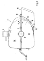
- a muffler housing 2 consists of two half shells 2A and 2B, which on their Circumferential edges are connected to one another in such a way that a flanged collar edge 4 is trained.
- the silencer housing 2 is for a double-flow exhaust system formed, for which two on the two sides of the rear silencer housing inlet-side openings 6 (only one side shown in FIG. 5) are provided to which are flanged according to two exhaust pipes, not shown.
- a suspension 8 enables the mounting of the silencer housing 2 on the chassis Motor vehicle.
- the rear silencer housing 2 has two openings provided with a collar 10 12, in each of which the end of a arranged in the rear silencer housing 2 Exhaust pipe 14 is inserted and welded to the collar 10. Because both collars 10 or openings 12 lie behind one another, in FIG. 5 there is only one collar 10 or an exhaust pipe 14 recognizable.
- On the underside of the lower half shell 2B of the Muffler housing 2 is attached to a tab 16 provided with an opening, those for attaching a mountable outlet pipe described in more detail below 18 is provided.
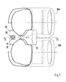
- the outlet pipe 18 consists of two interconnected, double-walled individual tubes 18A and 18B.
- Fastening element 20 is provided, which for example on the two individual tubes 18A and 18B is fixed by spot welding.
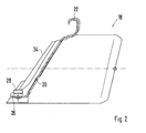
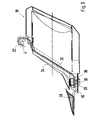
- the fastener 20 forms in Reference to the outlet pipe 18 mounted on the rear silencer housing 2 at the top Hook 22 and below a holding tab 26 provided with an opening 24.
- a nut 28 soldered or welded on.
- the exhaust pipe 18 is mounted on the rear silencer housing 2 in the following way:
Landscapes
- Engineering & Computer Science (AREA)
- Chemical & Material Sciences (AREA)
- Combustion & Propulsion (AREA)
- Mechanical Engineering (AREA)
- General Engineering & Computer Science (AREA)
- Exhaust Silencers (AREA)
Abstract
Description
- Fig. 1
- eine Draufsicht auf ein montierbares Auslassrohr eines Endschalldämpfers,
- Fig. 2
- einen Schnitt entlang der Linie II-II in Fig. 1,
- Fig. 3
- eine Seitenansicht des Auslassrohres im Schnitt,
- Fig. 4
- eine Ansicht des Auslassrohres von hinten und
- Fig. 5
- eine Seitenansicht des Endschalldämpfers mit montiertem Auslassrohr.
Claims (5)
- Montierbares Auslassrohr für einen Endschalldämpfer eines Kraftfahrzeuges, mit Mitteln zum Befestigen an einem Endschalldämpfergehäuse, dadurch gekennzeichnet, dass am Auslassrohr (18) ein Haken (22) vorgesehen ist, der am Endschalldämpfergehäuse (2) einhängbar ist und dass am Auslassrohr (18) eine mit einer Öffnung (24) versehene Haltelasche (26) angeordnet ist, die am Endschalldämpfergehäuse (2) über eine Mutter-Schraubenverbindung (28, 30) befestigbar ist.
- Montierbares Auslassrohr nach Anspruch 1, dadurch gekennzeichnet, dass der Haken (22) und die Haltelasche (26) aus einem Blechstreifen (20) herausgebildet sind, der zwischen zwei Einzelrohren (18a, 18b) des Auslassrohres (18) befestigt ist.
- Montierbares Auslassrohr nach Anspruch 1 oder 2, dadurch gekennzeichnet, dass eine mit der Öffnung (24) in der Haltelasche (26) korrespondierende Mutter (28) auf der Haltelasche (26) aufgeschweißt oder aufgelötet ist.
- Endschalldämpfer für ein Kraftfahrzeug mit einem Gehäuse, das mindestens eine einlassseitige und eine auslassseitige Öffnung aufweist, wobei an der auslassseitigen Öffnung (12) ein montierbares Auslassrohr (18) zumindest nach einem der Ansprüche 1 bis 3 vorgesehen ist und dass das Gehäuse aus zwei Halbschalen (2A, 2B) besteht, die über ihre umgebördelten Ränder (4) miteinander verbunden sind und dass an der dem Auslassrohr (18) zugewandten Seite des Gehäuses (2) eine mit einer Öffnung versehene Lasche (16) vorgesehen ist, die über eine Mutter- Schraubenverbindung (28, 30) mit der am Auslassrohr (18) vorgesehenen Haltelasche (26) verbunden ist.
- Endschalldämpfer nach Anspruch 4, dadurch gekennzeichnet, dass das Endschalldämpfergehäuse (2) zwei mit jeweils einem Kragen (10) versehene Auslassöffnungen (12) aufweist, in denen jeweils das Ende eines Abgasrohres (14) Aufnahme findet.
Applications Claiming Priority (2)
| Application Number | Priority Date | Filing Date | Title |
|---|---|---|---|
| DE10123567A DE10123567A1 (de) | 2001-05-15 | 2001-05-15 | Montierbares Auslassrohr für einen Endschalldämpfer sowie Endschalldämpfer für ein Kraftfahrzeug |
| DE10123567 | 2001-05-15 |
Publications (3)
| Publication Number | Publication Date |
|---|---|
| EP1258607A2 true EP1258607A2 (de) | 2002-11-20 |
| EP1258607A3 EP1258607A3 (de) | 2004-11-17 |
| EP1258607B1 EP1258607B1 (de) | 2007-03-28 |
Family
ID=7684839
Family Applications (1)
| Application Number | Title | Priority Date | Filing Date |
|---|---|---|---|
| EP02010399A Expired - Lifetime EP1258607B1 (de) | 2001-05-15 | 2002-05-08 | Montierbares Auslassrohr für einen Endschalldämpfer sowie Endschalldämpfer für ein Kraftfahrzeug |
Country Status (4)
| Country | Link |
|---|---|
| US (1) | US6913111B2 (de) |
| EP (1) | EP1258607B1 (de) |
| JP (1) | JP2003003839A (de) |
| DE (2) | DE10123567A1 (de) |
Cited By (1)
| Publication number | Priority date | Publication date | Assignee | Title |
|---|---|---|---|---|
| CN106041399A (zh) * | 2016-07-14 | 2016-10-26 | 苏州事达同泰汽车零部件有限公司 | 汽车装饰尾管焊接工装 |
Families Citing this family (4)
| Publication number | Priority date | Publication date | Assignee | Title |
|---|---|---|---|---|
| US20060065480A1 (en) * | 2004-09-28 | 2006-03-30 | Leehaug David J | Muffler and heat shield assembly |
| JP2008111357A (ja) * | 2006-10-30 | 2008-05-15 | Yamaha Motor Co Ltd | 自動二輪車の排気装置 |
| US20080121458A1 (en) * | 2006-11-29 | 2008-05-29 | Norris Gregory Sturgis | Harmonic tone exhaust extension |
| KR101405197B1 (ko) * | 2012-12-12 | 2014-06-10 | 기아자동차 주식회사 | 소음장치의 테일 파이프 |
Citations (1)
| Publication number | Priority date | Publication date | Assignee | Title |
|---|---|---|---|---|
| DE19914426A1 (de) | 1999-03-30 | 2000-10-12 | Daimler Chrysler Ag | Doppelwandiges Endrohr für ein Abgasrohr einer Abgasanlage eines Kraftfahrzeuges |
Family Cites Families (14)
| Publication number | Priority date | Publication date | Assignee | Title |
|---|---|---|---|---|
| US1995840A (en) * | 1933-04-24 | 1935-03-26 | John J Compo | Muffler pipe connecter |
| US5073353A (en) * | 1989-11-14 | 1991-12-17 | Nickson Industries, Inc. | Catalytic converter front flange and method of making same |
| JPH0472417A (ja) * | 1990-07-11 | 1992-03-06 | Nissan Motor Co Ltd | 排気装置の支持構造 |
| US5164551A (en) * | 1990-12-03 | 1992-11-17 | Ap Parts Manufacturing Co. | Stamp formed muffler with compound reinforcement pattern for preventing shell ring |
| DE4205454A1 (de) * | 1992-02-22 | 1993-08-26 | H J Kuepper Gmbh & Co Kg | Einrichtung zum anschliessen eines rohrkruemmers an einen zylinderkopf |
| US6070695A (en) * | 1995-01-11 | 2000-06-06 | Kabushiki Kaisha Yutaka Giken | Silencer |
| JPH08319825A (ja) * | 1995-05-29 | 1996-12-03 | Suzuki Motor Corp | マフラー支持構造 |
| JP3309949B2 (ja) * | 1996-03-11 | 2002-07-29 | カルソニックカンセイ株式会社 | 消音器へのブラケット取付構造 |
| JP3816581B2 (ja) * | 1996-06-21 | 2006-08-30 | 株式会社共立 | 内燃エンジンのマフラー |
| US5740846A (en) * | 1996-10-11 | 1998-04-21 | Larson; L. Robert | Hose adapter for use in connecting a proconditioned air hose to an aircraft |
| DE19653908A1 (de) * | 1996-12-21 | 1998-06-25 | Daimler Benz Ag | Einrichtung zum Anschluß eines Rohrkrümmers |
| IT1301837B1 (it) * | 1998-06-29 | 2000-07-07 | Crc Ct Ricerche Cagiva S A | Dispostivo di fissaggio di almeno un collettore di scarico o diaspirazione di un motore endotermico |
| DE29904934U1 (de) * | 1999-03-18 | 2000-07-27 | Zeuna-Stärker GmbH & Co. KG, 86154 Augsburg | Nachschalldämpfer für die Abgasanlage eines Kraftfahrzeugs |
| US6520285B2 (en) * | 2000-08-31 | 2003-02-18 | Mark Tobias | Audible tuning apparatus for a muffler |
-
2001
- 2001-05-15 DE DE10123567A patent/DE10123567A1/de not_active Ceased
-
2002
- 2002-05-08 EP EP02010399A patent/EP1258607B1/de not_active Expired - Lifetime
- 2002-05-08 DE DE50209813T patent/DE50209813D1/de not_active Expired - Lifetime
- 2002-05-09 JP JP2002133821A patent/JP2003003839A/ja not_active Withdrawn
- 2002-05-14 US US10/143,854 patent/US6913111B2/en not_active Expired - Fee Related
Patent Citations (1)
| Publication number | Priority date | Publication date | Assignee | Title |
|---|---|---|---|---|
| DE19914426A1 (de) | 1999-03-30 | 2000-10-12 | Daimler Chrysler Ag | Doppelwandiges Endrohr für ein Abgasrohr einer Abgasanlage eines Kraftfahrzeuges |
Cited By (2)
| Publication number | Priority date | Publication date | Assignee | Title |
|---|---|---|---|---|
| CN106041399A (zh) * | 2016-07-14 | 2016-10-26 | 苏州事达同泰汽车零部件有限公司 | 汽车装饰尾管焊接工装 |
| CN106041399B (zh) * | 2016-07-14 | 2017-08-11 | 苏州事达同泰汽车零部件有限公司 | 汽车装饰尾管焊接工装 |
Also Published As
| Publication number | Publication date |
|---|---|
| DE50209813D1 (de) | 2007-05-10 |
| JP2003003839A (ja) | 2003-01-08 |
| US6913111B2 (en) | 2005-07-05 |
| US20020185332A1 (en) | 2002-12-12 |
| DE10123567A1 (de) | 2002-11-28 |
| EP1258607A3 (de) | 2004-11-17 |
| EP1258607B1 (de) | 2007-03-28 |
Similar Documents
| Publication | Publication Date | Title |
|---|---|---|
| EP1860295B1 (de) | Kraftfahrzeug mit einer Abgasanlage | |
| DE112012002385B4 (de) | Halter | |
| EP1428743B1 (de) | Heckverkleidungsteil mit einer daran befestigten Abgasendrohrblende | |
| DE102005026376C5 (de) | Fahrzeugschalldämpfer | |
| EP1165947B1 (de) | Doppelwandiges endrohr fur ein abgasrohr einer abgasanlage eines kraftfahrzeuges | |
| DE4425852C2 (de) | Frontkarosseriebauteil für ein Kraftfahrzeug | |
| DE60302258T2 (de) | Abgasrückführeinrichtung für Brennkraftmaschinen | |
| EP0848144B1 (de) | Endrohr für Abgasrohr einer Abgasanlage eines Kraftfahrzeuges | |
| DE10261966B4 (de) | Luftheizgerät zur Integration in eine luftführende Gehäuseanordnung | |
| DE102010052938B4 (de) | Abgaseinrichtung für Quermotor | |
| DE10211591B4 (de) | Luftheizgerät zur Integration in eine luftführende Gehäuseanordnung | |
| DE19633563C2 (de) | Abgasanlage einer Brennkraftmaschine | |
| DE29509434U1 (de) | Entkopplungselement für Schwingungen in Rohrleitungen | |
| EP1258607B1 (de) | Montierbares Auslassrohr für einen Endschalldämpfer sowie Endschalldämpfer für ein Kraftfahrzeug | |
| DE102004023585B4 (de) | Katalysatorbefestigung, Befestigung am Flansch Katalysatorausgang, ohne Schweißverbindung | |
| DE102004022721A1 (de) | Zweiflutige Abgasanlage für eine Brennkraftmaschine | |
| DE102004018693A1 (de) | Abgasanlage | |
| EP1596049B1 (de) | Verbindungsvorrichtung | |
| EP3327261B1 (de) | Abgasbehandlungsanordnung | |
| DE19800061A1 (de) | Sauganlage für eine Verbrennungsluftversorgung einer Brennkraftmaschine | |
| EP3754165B1 (de) | Komponente für eine abgasanlage einer brennkraftmaschine | |
| EP3702592B1 (de) | Abgaskonverter-gehäusestruktur | |
| EP1081024A2 (de) | Fahrzeugvorderbau mit einem Wasserkasten | |
| DE102017216226B4 (de) | Antriebseinrichtung für ein Kraftfahrzeug sowie entsprechendes Kraftfahrzeug | |
| DE10038558B4 (de) | Vorrichtung zum Verbinden einer Rohrleitung mit einem Verbrennungsmotor |
Legal Events
| Date | Code | Title | Description |
|---|---|---|---|
| PUAI | Public reference made under article 153(3) epc to a published international application that has entered the european phase |
Free format text: ORIGINAL CODE: 0009012 |
|
| AK | Designated contracting states |
Kind code of ref document: A2 Designated state(s): AT BE CH CY DE DK ES FI FR GB GR IE IT LI LU MC NL PT SE TR |
|
| AX | Request for extension of the european patent |
Free format text: AL;LT;LV;MK;RO;SI |
|
| PUAL | Search report despatched |
Free format text: ORIGINAL CODE: 0009013 |
|
| AK | Designated contracting states |
Kind code of ref document: A3 Designated state(s): AT BE CH CY DE DK ES FI FR GB GR IE IT LI LU MC NL PT SE TR |
|
| AX | Request for extension of the european patent |
Extension state: AL LT LV MK RO SI |
|
| 17P | Request for examination filed |
Effective date: 20050517 |
|
| AKX | Designation fees paid |
Designated state(s): DE FR GB IT |
|
| GRAP | Despatch of communication of intention to grant a patent |
Free format text: ORIGINAL CODE: EPIDOSNIGR1 |
|
| GRAS | Grant fee paid |
Free format text: ORIGINAL CODE: EPIDOSNIGR3 |
|
| GRAA | (expected) grant |
Free format text: ORIGINAL CODE: 0009210 |
|
| AK | Designated contracting states |
Kind code of ref document: B1 Designated state(s): DE FR GB IT |
|
| REG | Reference to a national code |
Ref country code: GB Ref legal event code: FG4D Free format text: NOT ENGLISH |
|
| REF | Corresponds to: |
Ref document number: 50209813 Country of ref document: DE Date of ref document: 20070510 Kind code of ref document: P |
|
| GBT | Gb: translation of ep patent filed (gb section 77(6)(a)/1977) |
Effective date: 20070614 |
|
| PLBE | No opposition filed within time limit |
Free format text: ORIGINAL CODE: 0009261 |
|
| STAA | Information on the status of an ep patent application or granted ep patent |
Free format text: STATUS: NO OPPOSITION FILED WITHIN TIME LIMIT |
|
| 26N | No opposition filed |
Effective date: 20080102 |
|
| REG | Reference to a national code |
Ref country code: FR Ref legal event code: TQ |
|
| REG | Reference to a national code |
Ref country code: FR Ref legal event code: CD |
|
| REG | Reference to a national code |
Ref country code: GB Ref legal event code: 732E Free format text: REGISTERED BETWEEN 20110310 AND 20110316 |
|
| REG | Reference to a national code |
Ref country code: GB Ref legal event code: 732E Free format text: REGISTERED BETWEEN 20110331 AND 20110406 |
|
| REG | Reference to a national code |
Ref country code: FR Ref legal event code: TQ |
|
| PGFP | Annual fee paid to national office [announced via postgrant information from national office to epo] |
Ref country code: FR Payment date: 20110607 Year of fee payment: 10 |
|
| PGFP | Annual fee paid to national office [announced via postgrant information from national office to epo] |
Ref country code: GB Payment date: 20110520 Year of fee payment: 10 |
|
| PGFP | Annual fee paid to national office [announced via postgrant information from national office to epo] |
Ref country code: IT Payment date: 20110524 Year of fee payment: 10 |
|
| GBPC | Gb: european patent ceased through non-payment of renewal fee |
Effective date: 20120508 |
|
| PG25 | Lapsed in a contracting state [announced via postgrant information from national office to epo] |
Ref country code: IT Free format text: LAPSE BECAUSE OF NON-PAYMENT OF DUE FEES Effective date: 20120508 |
|
| REG | Reference to a national code |
Ref country code: FR Ref legal event code: ST Effective date: 20130131 |
|
| PG25 | Lapsed in a contracting state [announced via postgrant information from national office to epo] |
Ref country code: GB Free format text: LAPSE BECAUSE OF NON-PAYMENT OF DUE FEES Effective date: 20120508 Ref country code: FR Free format text: LAPSE BECAUSE OF NON-PAYMENT OF DUE FEES Effective date: 20120531 |
|
| PGFP | Annual fee paid to national office [announced via postgrant information from national office to epo] |
Ref country code: DE Payment date: 20160520 Year of fee payment: 15 |
|
| REG | Reference to a national code |
Ref country code: DE Ref legal event code: R119 Ref document number: 50209813 Country of ref document: DE |
|
| PG25 | Lapsed in a contracting state [announced via postgrant information from national office to epo] |
Ref country code: DE Free format text: LAPSE BECAUSE OF NON-PAYMENT OF DUE FEES Effective date: 20171201 |