EP1258170B1 - Kochfeld mit temperaturfühler - Google Patents
Kochfeld mit temperaturfühler Download PDFInfo
- Publication number
- EP1258170B1 EP1258170B1 EP01903691A EP01903691A EP1258170B1 EP 1258170 B1 EP1258170 B1 EP 1258170B1 EP 01903691 A EP01903691 A EP 01903691A EP 01903691 A EP01903691 A EP 01903691A EP 1258170 B1 EP1258170 B1 EP 1258170B1
- Authority
- EP
- European Patent Office
- Prior art keywords
- heating element
- heating
- cooker hob
- region
- temperature sensor
- Prior art date
- Legal status (The legal status is an assumption and is not a legal conclusion. Google has not performed a legal analysis and makes no representation as to the accuracy of the status listed.)
- Expired - Lifetime
Links
Images

Classifications
-
- H—ELECTRICITY
- H05—ELECTRIC TECHNIQUES NOT OTHERWISE PROVIDED FOR
- H05B—ELECTRIC HEATING; ELECTRIC LIGHT SOURCES NOT OTHERWISE PROVIDED FOR; CIRCUIT ARRANGEMENTS FOR ELECTRIC LIGHT SOURCES, IN GENERAL
- H05B3/00—Ohmic-resistance heating
- H05B3/68—Heating arrangements specially adapted for cooking plates or analogous hot-plates
- H05B3/74—Non-metallic plates, e.g. vitroceramic, ceramic or glassceramic hobs, also including power or control circuits
- H05B3/746—Protection, e.g. overheat cutoff, hot plate indicator
-
- H—ELECTRICITY
- H05—ELECTRIC TECHNIQUES NOT OTHERWISE PROVIDED FOR
- H05B—ELECTRIC HEATING; ELECTRIC LIGHT SOURCES NOT OTHERWISE PROVIDED FOR; CIRCUIT ARRANGEMENTS FOR ELECTRIC LIGHT SOURCES, IN GENERAL
- H05B2213/00—Aspects relating both to resistive heating and to induction heating, covered by H05B3/00 and H05B6/00
- H05B2213/07—Heating plates with temperature control means
Definitions
- the present invention relates to a hob according to the preamble of claim 1, and a corresponding heating element and a suitable element.
- Such a hob is known from the document DE 37 03 768 C2 in which a device for detecting the temperature of a heated by means of heating coils or halogen lamps glass-ceramic plate is disclosed with a temperature sensor. This emits a signal corresponding to the temperature of the glass ceramic for a control circuit.
- the heating coils or the halogen lamps are arranged in the interior of a pot-like insulating support and heat the glass ceramic plate via direct radiation.
- the edge of the insulating substrate is spring-loaded on the underside of the glass-ceramic plate, and the temperature sensor is disposed outside the interior of the insulating substrate but inside the heating element.
- the temperature sensor is further in thermally conductive connection with the underside of the glass ceramic plate, wherein the temperature sensor is arranged in a receptacle in the edge of the insulating support.
- the receptacle is arranged at a distance x to the inside of the edge of the insulating support, the minimum value of which is selected so that the short-term temperature changes occurring when the heating coils or the halogen lamps are switched on and off have only a negligible influence on the temperature sensor.
- the maximum value of the distance x is chosen such that the delay in the control characteristic caused by the thermal conductivity of the glass ceramic plate results in a small hysteresis. As a distance x widths of 3 mm to 6 mm have proven to be advantageous.
- the temperature sensor is introduced into the introduced or indented receptacle on the upper side of the projection, which protrudes into the interior of the insulating support, and is in heat-conducting connection with the underside of the glass ceramic plate.
- the temperature sensor is indirectly held under spring tension on the underside of the glass ceramic plate in order to keep the heat transfer resistance between the glass ceramic plate and the temperature sensor small.
- a heating element for a cooking unit with a temperature sensor known.
- a heat transfer element in the form of a sheet is used, which is arranged partially overlapping the heated area between the radiators and the glass ceramic plate, but from the Heating element protrudes and there is in communication with the temperature sensor of the controller.
- the heat transfer element is fixed on the edge of the heating shell bearing by clamping and is usually on the underside of the glass ceramic plate. From the heat-sensing region of the heat transfer element, an outer section protrudes outwards beyond the edge of the heating element.
- the sensor socket of the temperature sensor is pressed by a compression spring to the underside of the heat transfer surface of the heat transfer element, which is supported on a leading the sensor socket, mounted on the outer portion of the heat transfer element holding mechanism.
- a compression spring to the underside of the heat transfer surface of the heat transfer element, which is supported on a leading the sensor socket, mounted on the outer portion of the heat transfer element holding mechanism.
- an electrical NTC or PTC sensor can be used, which is pressed resiliently or is fixedly attached to the outer portion of the heat transfer element.
- the heat transfer element can be grounded, providing contact protection.
- thermocouple is held in good thermal contact with the underside of the glass ceramic plate by means of the insulation block.
- EP 0 943 870 A1 discloses a temperature sensing and limiting apparatus for use in an electric radiant heater including at least one heating element, the apparatus comprising: an elongate tubular housing configured to at least partially cross over the heater so as to be external to the heating element is heated; a component provided in the housing is and provides an electrical parameter that varies with temperature; and at least one heat detecting portion of a heat-responsive bimetallic shut-off device provided in the case, the shut-off device having the function of shutting off the heater at a predetermined temperature.
- the component and / or the bimetallic disconnecting device is / are in a heat-conducting relationship with the housing.
- the bimetallic shutdown device or a portion thereof is housed in an end region of the tubular housing.
- the end region is positioned for positioning on a peripheral region of the heater, and the component providing an electrical parameter that varies with temperature is remote in the tubular housing and radially in the same direction from the bimetallic shutdown device Section of it housed.
- DE 42 24 934 A1 discloses a sensor arrangement for a pan detection system, in which the pot detection takes place with high-frequency circuit technology, wherein the pot detection sensor below cooking hobs, for example glass ceramic cooktops is arranged, wherein at least two capacitive, electrically conductive, temperature-resistant pan detection sensors preferably arranged on the outer edge of radiant heaters are, by means of an evaluation automatically the respectively necessary active heating zone is adapted to a detected pot size.
- the respective heating zone is heated by a heating coil exposed in a thermal insulation shell.
- the sensors it is important that they are mounted as close as possible to the glass ceramic underside between radiant heater and glass ceramic plate, while on the one hand while sitting as close to the glass ceramic bottom, but on the other hand as possible to avoid stress concentrations on the glass ceramic flush with a sealing ring of the radiant heaters. In this case, an immediate tip or line-shaped contact of the sensors and the connecting wire to the glass ceramic is avoided.
- Object of the present invention is to provide a generic hob and a corresponding heating element, which has a good accuracy of measurement with simple installation.
- the temperature sensor is attached to an element extending from an area within the heating element in a region outside the heating element, and that the element has a receiving portion within the heating element for the temperature sensor and a mounting portion for the attachment of the element, in particular on the heating element, and / or a connection portion for the connection of at least one electrical line in each case outside of the heating element, which receiving portion radially laterally offset from the mounting portion or connection portion.
- a corresponding heating element and an element for the heating element are further provided.
- the relative position of the temperature sensor to the element and their heat conduction behavior are precisely defined and it is a pre-testable and pre-testable and easy to assemble montagetechnisch because larger, provided unit.
- mounting the assembly on the heating element is only to pay attention to the correct attachment of the heat conducting element on the heating element. Due to the thermal coupling of the heat-conducting element to the underside of the hob plate within the heating element and the simultaneous attachment of the temperature sensor to the element is thus coupled with easy positioning and assembly of the temperature sensor optimally to the hob plate or to a potted thereon pot.
- the temperature sensor is arranged in the region of a temperature limiter of the heating element.
- all electrical connections can be spatially combined in a manner that is favorable in terms of installation technology, and on the other hand, the respective minimum distances between the electrical connections can be securely maintained with one another according to the relevant VDE regulations.
- the temperature limiter of the mounting space in the region of the outer peripheral wall of the heating element is limited, on the other hand, it is favorable if the various electrical connections of the temperature limiter and the temperature sensor are as close as safety-friendly together.
- the heat-conducting element in the region of the outer peripheral wall of the heating element or the insulating support fixed directly or with the aid of an intermediate mounting part, in particular screwed.
- the intermediate mounting part is fixed in the bottom of the insulating support of the heating element and extends in the region of the outer peripheral wall of the heating element, in which the element is in turn screwed to the intermediate mounting part.
- the element can be screwed to the outer peripheral wall of the heating element at different heights.
- the temperature sensor is attached to the underside of the element.
- a large plane contact surface for improving the heat conduction from the underside of the glass ceramic plate to the temperature sensor can be realized.
- the temperature sensor is characterized by the larger area element in the assembly process, e.g. when falling the unit element / temperature sensor, better mechanically protected.
- the element is formed at least in two parts.
- a receiving part for the temperature sensor consists of a softer material in order to be able to geometrically reshape the receiving part in an application-specific and safety-related manner.
- the remainder of the element may consist of a different material, wherein in particular a spring material is suitable for being able to press the element in a defined manner against the underside of the glass-ceramic plate.
- the element is designed as a torsion spring, wherein the torsion region of the spring element is provided substantially outside the heating element and thus in a cooler area.
- a particularly compact unit is formed when the spring is substantially L-shaped.
- the element is designed to be electrically conductive and grounded in order to optimally meet the safety regulations with a simple structure.
- both the temperature sensor and the element by means of an insulating body is sufficiently shielded against emanating from a heating means of the heating element heat radiation.
- the electrical leads of the temperature sensor are connected to a first connection portion of the element or a fitting mounted there.
- the element can also have a second connection section, to which a grounding line of the element is connected.
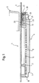
- a hob 1 has a hob plate 3, in particular made of glass ceramic, on (Fig. 1). Below the hob plate 3 different heating elements 5 of the hob are provided in a conventional manner, which are pressed in a known manner to the underside of the hob plate 3 (not shown). In the region of the heating element 5, the hob plate 3 is usually decorated accordingly on its upper side. In this heated area a cooking vessel 6 is shut off. The bottom of the cooking vessel 6 is in the cold state often only in the edge region of the heating element 5 in an annular surface on the hob plate 3, while in the central residual region of the pot bottom is spaced by an air gap from the plate (Fig. 1). In the heated state, this air gap is reduced or ideally to approximately zero by the known thermally induced movement of the pot bottom.
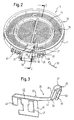
- the heating element 5 has a cup-shaped sheet metal pot 7, in which a circular disk-shaped insulation plate 9 is located. Furthermore, an inner insulation ring 11 and an outer insulation ring 13 corresponding to a two-circuit heating arrangement are provided within the sheet metal pot 7 on the insulation plate 9. As a result, the interior of the heating element 5 is separated into an inner and an outer heating region, in each of which a Bandterrorismleiter 15 extends (Fig. 1, Fig. 2). In known manner, a Schuleiteran gleichteil 17 is fixed in the region of the outer peripheral wall of the sheet metal pot 7, which is on the one hand conductively connected to the Bandterrorismn 15 and on the other hand to not shown electrical supply lines of the hob 1 can be connected (Fig. 2).
- the heating element 5 also has a known temperature limiter 19, whose rod extends transversely across the heated region of the heating element.
- the terminal block of the temperature limiter 19 has the known and usual, laterally issued Kunststoffflachsteckite for connection to the power supply line or to the Schuleiteranschlußteil 17 of the heating element 5.
- an insulation block 21 is disposed in the region of the temperature limiter 19. This can serve the temperature limiter 19 in the region of sections of the band heating conductor guided below the insulation block 21 15 thermally shield against this.
- a receiving recess 23 is milled in the top thereof.
- a heat-conducting element 25 is arranged with its element hood 27 (FIGS.
- hood 27 is not seated directly on the bottom of the recess 23 so that the hood 27 can yield slightly to a blow on the hob plate 3. As a result, damage or breakage of the plate 3 can be avoided, especially if it is made of glass or glass ceramic material.
- the element hood 27 In the receiving space formed by the element hood 27 is by means of a temperature-resistant and thermally conductive ceramic adhesive 28 as a temperature sensor 29, a PT-500 probe embedded with its sensor leads 30 and thereby secured and guided.
- the material of the element cover 27 is X7 steel and the hood 27 is designed as a bent part.
- the hood material must have sufficiently good heat conduction properties, must be well deformable, as explained below, but sufficient mechanical stability throughout the temperature range of up to 350 - 400 ° C and maintained its properties even at these temperatures From serving as the top wall portion of the element hood 27th two side walls 31 are bent substantially at right angles downwards (FIG. 3). Also bent at right angles to the side walls 31 define bottom walls 33 a slot-shaped open bottom of the element cover 27.
- the front side of the receiving space of the hood is closed by a right angle bent from the top wall end wall 35.
- the hood-like design of the element 25 ensures that the safety-prescribed air and creepage distance to the live temperature sensor 29 is maintained in the event of breakage of the hob plate 3, without the base of the element 25 and the hood 27 and thus of the insulation block 21 too large to have to shape. More detailed explanations on the geometric design and arrangement of the temperature sensor 29, the element 25 and the insulation block 21 are made in connection with the description of the sketched in Fig. 5 third embodiment.
- the hood 27 is fixedly connected to a substantially L-shaped hood carrier 37 made of steel, preferably welded.
- the element hood 27 is seated on a connecting section 39 of the hood carrier 37 (FIG. 3).
- the top wall of the element hood 27 is slightly elevated relative to the top of the hood carrier 37 arranged and defines and limits a surface area A, in which the element 25 on the underside of the hob plate 3 is thermally conductive (Fig. 1, 2, 5). Due to the overlapping connection of hood 27 and hood carrier 37, the stability of the connection is also increased.
- the cage carrier 37 is made of 0.8 mm thick material in order to be suitable for the earthing plug-in connections described below, the element cover 27 is made of thinner material, which additionally simplifies their forming.
- the hood carrier 37 merges in a spring section 41 into a mounting section 43 (FIGS. 2, 3).
- the spring portion 41 is arranged substantially outside the heated region of the heating element 5 and the outer insulating ring 13.
- the mounting portion 43 of the hood support 37 has a rectangularly downward bent mounting plate 45 with mounting holes 47.
- the heat-conducting element 25 height adjustable via an intermediate mounting member 48 on the outer peripheral wall of the sheet metal pot 7 are fixed (Fig. 2).
- the intermediate mounting part 48 is bolted on the one hand to the underside of the sheet metal pot 7 in the bottom thereof (not shown). This part 48 extends approximately L-shaped from the bottom of the heating element to its side wall 7.
- the heat-conducting element 25 is then screwed to the intermediate mounting part 48 and thus defined in terms of height the position of the heat-conducting element 25 defined.
- the heat-conducting element 25 can also be screwed to the outer wall of the sheet-metal pot 7 in the region of the assembly openings 47.
- a connection part can be attached (not shown), with the one hand, the electrical sensor leads 30 of the temperature sensor 29 connectable, eg attachable, and are connected to the other hand electrical connection lines of a control unit 101 (Fig.
- connection part is further to ensure that the electrical connections of the PT temperature sensor 29 to ground or the grounded hood carrier 37 are isolated.
- the temperature sensor and the sensor lines 30 are covered over the entire length of the heat-conducting element 25 deck. to better guidance of the lines 30, these can be glued to the underside of the element 25 in the region of the hood carrier 37 and / or held by formed on the carrier 37 guide elements.
- the mounting plate 45 has a flat pin 49 to which a grounding line 51 and their standardized AMP plug of the hob is directly pluggable. As a result, the heat-conducting element 25 is set to ground potential.
- the ohmic resistance of the element 25 is at a value of 0.1 ohms or less in order to withstand a continuous current load of at least 25 amperes. Furthermore, the heat-conducting element 25 must not be made too stiff in order to be able to give in properly under mechanical loading or movement of the hob plate 3. Otherwise would be feared by a too stiff concern of the element 25 and the element cover 27 on the hob plate 3 hotplate chipping on the underside of the plate 3 or possibly also their breakage.
- Fig. 4 is shown in sections in a cross-sectional view transversely to the longitudinal extent of the element and thus approximately perpendicular to the line II in Fig. 2 of the hob shown in which the temperature sensor 29 together with a heat conducting element 75 in the region of the insulation block 21 similar to the first embodiment is arranged.
- the heat-conducting element 25 has no element hood, but rather an element shell 77. This element shell is also arranged in a suitable receiving recess 23 of the insulation block 21.
- the insulation shell lies in its edge regions in an annular surface directly on the underside of the glass ceramic plate 3 and is thus in thermally conductive connection with it.
- the temperature sensor 29 is arranged, wherein the shell is additionally filled by a thermal paste.
- the heat conducting element 75 not shown in detail could otherwise be like the heat conducting element 25 be formed of the first embodiment. For safety reasons, however, the temperature sensor 29 is operated with a safety extra-low voltage or transmits its measuring signal without contact from the heating element.
- the heat-conducting element 85 designed in the shape of a hood, for example, has an element hood 87 which corresponds to that of the first exemplary embodiment.
- a mounting portion 89 of the hood support 37 is arranged laterally offset radially to the receiving portion of the element cover 87.
- Fig. 5 is shown schematically in which area A, the heat conducting element 85 is thermally in contact with the underside of the hob plate 3.
- the size of the surface is about 50 to 100 mm 2 . It is also shown that the contact surface A is about 10 times larger than a base B of the temperature sensor 29.
- the insulation block is still small enough to avoid an adverse shading of the cooking vessel bottom 6 and thereby caused undesirable uneven heat distribution in the pan bottom when heating or frying.
- the heat-conducting element 25 is still sufficiently thermally coupled to the region of the hob plate, which is heated directly by the heat radiation of the heating means 15.
- the temperature sensor 29 relative to the hob plate 3 is covered by a grounded protective element 27 in compliance with the required according to 4 or 8 mm creepage and air gap.
- a sufficiently good thermal contact between the smaller area temperature sensor and the hob plate 3 is made.
- the measuring surface A is coupled by a high-temperature lubricant to the cooktop plate underside, which consists in particular of glass ceramic material, in order to achieve improved heat transfer and impact resistance improved damping.
- FIG. 6 schematically shows a block diagram showing the most important components of the cooktop.
- the control unit 101 regulates the heating power of the BandMapleiters 15 according to the measured values of the temperature sensor 29 to the predetermined by an input unit 103 target value. As a result, it can be achieved, in particular, that burning is virtually impossible during roasting.
Landscapes
- Chemical & Material Sciences (AREA)
- Engineering & Computer Science (AREA)
- Ceramic Engineering (AREA)
- Electric Stoves And Ranges (AREA)
- Cookers (AREA)
- Control Of Resistance Heating (AREA)
- Resistance Heating (AREA)
- Measuring Temperature Or Quantity Of Heat (AREA)
Description
- Die vorliegende Erfindung betrifft ein Kochfeld nach dem Oberbegriff des Patentanspruches 1, sowie ein entsprechendes Heizelement und ein geeignetes Element.
- Ein derartiges Kochfeld ist bekannt aus der Druckschrift
DE 37 03 768 C2 , wobei eine Vorrichtung zum Erfassen der Temperatur einer mittels Heizwicklungen oder Halogenlampen aufgeheizten Glaskeramikplatte mit einem Temperatursensor offenbart ist. Dieser gibt ein der Temperatur der Glaskeramik entsprechendes Signal für eine Regelschaltung ab. Die Heizwicklungen oder die Halogenlampen sind im Innenraum eines topfartigen Isolierträgers angeordnet und erwärmen die Glaskeramikplatte über direkte Strahlung. Der Rand des Isolierträgers liegt an der Unterseite der Glaskeramikplatte unter Federspannung an, und der Temperatursensor ist außerhalb des Innenraums des Isolierträgers, jedoch innerhalb des Heizelementes, angeordnet. Der Temperatursensor steht weiterhin mit der Unterseite der Glaskeramikplatte in wärmeleitender Verbindung, wobei der Temperatursensor in einer Aufnahme im Rand des Isolierträgers angeordnet ist. Die Aufnahme ist in einem Abstand x zur Innenseite des Randes des Isolierträgers angeordnet, dessen minimaler Wert so gewählt ist, dass die beim Ein- und Ausschalten der Heizwicklungen oder der Halogenlampen entstehenden kurzzeitigen Temperaturänderungen nur einen vernachlässigbaren Einfluss auf den Temperatursensor haben. Der maximale Wert des Abstandes x ist so gewählt, dass die durch die Wärmeleitfähigkeit der Glaskeramikplatte bedingte Verzögerung in der Regelcharakteristik eine kleine Hysterese ergibt. Als Abstand x haben sich Weiten von 3 mm bis 6 mm als vorteilhaft erwiesen. Der Temperatursensor ist in die eingebrachte oder eingedrückte Aufnahme auf der Oberseite des Ansatzes, der in den Innenraum des Isolierträgers ragt, eingebracht und steht mit der Unterseite der Glaskeramikplatte in wärmeleitender Verbindung. Der Temperatursensor ist mittelbar unter Federspannung an der Unterseite der Glaskeramikplatte gehalten, um den Wärmeübergangswiderstand zwischen der Glaskeramikplatte und dem Temperatursensor klein zu halten. - Weiterhin ist aus der Druckschrift
EP 0 021 107 A1 ein Heizelement für eine Kocheinheit mit einem Temperaturfühler bekannt. Um eine vollständige Beheizung der gesamten Fläche des Heizelementes beizubehalten und trotzdem den Temperaturfühler des Reglers eng an die Beheizung zu koppeln, wird ein Wärmeübertragungselement in Form eines Bleches verwendet, das den beheizten Bereich teilweise überdeckend zwischen den Heizkörpern und der Glaskeramikplatte angeordnet ist, jedoch aus dem Heizelement herausragt und dort mit dem Temperaturfühler des Reglers in Verbindung steht. Das Wärmeübertragungselement ist auf dem Rand der die Beheizung tragenden Schale durch Festklemmen befestigt und liegt normalerweise an der Unterseite der Glaskeramikplatte an. Von dem die Wärme abfühlenden Bereich des Wärmeübertragungselementes ragt ein Aussenabschnitt nach aussen über den Rand des Heizelementes hinaus. Er ist einstückig mit dem vorgenannten Bereich ausgebildet, zu diesem im wesentlichen parallel, jedoch durch eine Abbiegung etwas nach unten versetzt, so dass der Aussenabschnitt nicht an der Unterseite der Glaskeramikplatte anliegt. Die Fühlerdose des Temperaturfühlers wird durch eine Druckfeder an die Unterseite der Wärmeübertragungsfläche des Wärmeübertragungselementes angedrückt, die sich an einem die Fühlerdose führenden, an dem Außenabschnitt des Wärmeübertragungselementes angebrachten Haltemechanismus abstützt. Es sind jedoch auch andere Fühlerarten und -anbringungen möglich. So kann beispielsweise auch ein elektrischer NTC- oder PTC-Fühler verwendet werden, der federnd angedrückt wird oder fest an dem Außenabschnitt des Wärmeübertragungselementes angebracht ist. Das Wärmeübertragungselement kann gewünschtenfalls geerdet werden, wodurch ein Berührungsschutz vorliegt. - Weiterhin ist aus der Druckschrift
US 4,447,710 ein Glaskeramikkochfeld bekannt, bei dem im Randbereich des Heizelementes ein Isolationskörper angeordnet ist, auf dem ein Temperaturfühler, beispielsweise ein Thermoelement sitzt. Das Thermoelement ist in einem guten thermischen Kontakt mit der Unterseite der Glaskeramikplatte mittels des Isolationsblocks gehalten. -
EP 0 943 870 A1 offenbart eine Temperaturerfassungs- und -begrenzungsvorrichtung für die Verwendung in einer elektrischen Strahlungsheizung, die wenigstens ein Heizelement beinhaltet, wobei die Vorrichtung Folgendes umfasst: ein längliches röhrenförmiges Gehäuse, das so gestaltet ist, dass es die Heizung wenigstens teilweise überquert, so dass es extern von dem Heizelement erhitzt wird; eine Komponente, die in dem Gehäuse vorgesehen ist und einen elektrischen Parameter bereitstellt, der sich in Abhängigkeit von der Temperatur ändert; und wenigstens einen Wärmeerfassungsabschnitt einer auf Wärme ansprechenden bimetallischen Abschaltvorrichtung, die in dem Gehäuse vorgesehen ist, wobei die Abschaltvorrichtung die Aufgabe hat, die Heizung bei einer vorbestimmten Temperatur abzuschalten. Dabei befindet/befinden die Komponente und/oder die bimetallische Abschaltvorrichtung sich in einer Wärmeleitbeziehung zu dem Gehäuse. Ferner ist die bimetallische Abschaltvorrichtung oder ein Abschnitt davon in einer Endregion des röhrenförmigen Gehäuses untergebracht. Die Endregion ist für eine Positionierung an einer Umfangsregion der Heizung angeordnet, und die Komponente, die einen elektrischen Parameter bereitstellt, der sich in Abhängigkeit von der Temperatur ändert, ist in dem röhrenförmigen Gehäuse abgelegen und radial in der gleichen Richtung von der bimetallischen Abschaltvorrichtung oder einem Abschnitt davon untergebracht. -
DE 42 24 934 A1 offenbart eine Sensoranordnung für ein Topferkennungssystem, bei der die Topferkennung mit Hochfrequenz-Schaltungstechnik erfolgt, wobei der Topferkennungssensor unterhalb von Kochfeldern, beispielsweise Glaskeramik-Kochfeldern, angeordnet ist, wobei mindestens zwei kapazitiv wirkende, elektrisch leitende, temperaturbeständige Topferkennungssensoren vorzugsweise am äußeren Rand von Strahlungsheizkörpern angeordnet sind, wobei mittels einer Auswerteelektronik automatisch die jeweils notwendige aktive Heizzone an eine detektierte Topfgröße anpassbar ist. Die jeweilige Heizzone wird durch eine in einer thermischen Isolationsschale offen liegende Heizwendel erhitzt. Für die Wirkung der Sensoren ist es wichtig, dass diese so nahe wie möglich an der Glaskeramik-Unterseite zwischen Strahlungsheizung und Glaskeramikplatte angebracht werden, wobei sie einerseits zwar möglichst nahe an der Glaskeramik-Unterseite sitzen, andererseits aber zur Vermeidung von Kerbspannungen auf die GlasKeramik möglichst bündig mit einem Dichtring der Strahlungsheizungen abschließen. Dabei muss ein unmittelbares spitzen- oder linienförmiges Anliegen der Sensoren und des Verbindungsdrahtes an die Glaskeramik vermieden wird. - Aufgabe der vorliegenden Erfindung ist es, ein gattungsgemäßes Kochfeld und ein entsprechendes Heizelement bereitzustellen, das bei einfacher Montage eine gute Meßgenauigkeit aufweist.
- Erfindungsgemäß ist dies dadurch erreicht, dass bei einem Kochfeld nach dem Oberbegriff des Patentanspruches 1 der Temperaturfühler an einem Element befestigt ist, das sich von einem Bereich innerhalb des Heizelementes in einen Bereich außerhalb des Heizelementes erstreckt, und daß das Element einen Aufnahmeabschnitt innerhalb des Heizelementes für den Temperaturfühler und einen Montageabschnitt für die Befestigung des Elementes, insbesondere am Heizelement, und/oder einen Anschlussabschnitt für den Anschluss zumindest einer elektrischen Leitung jeweils außerhalb des Heizelementes aufweist, welcher Aufnahmeabschnitt radial seitlich versetzt zum Montageabschnitt oder Anschlussabschnitt liegt. Erfindungsgemäß sind weiterhin ein entsprechendes Heizelement sowie ein Element für das Heizelement bereitgestellt. Durch den erfindungsgemäßen Aufbau sind die relative Position des Temperaturfühlers zum Element und deren Wärmeleitungsverhalten genau festgelegt und es ist eine vormontierbare und vorab testbare sowie montagetechnisch einfach handhabbare, weil größere, Baueinheit bereitgestellt. Bei der Montage der Anordnung am Heizelement ist nur noch auf die fehlerfreie Befestigung des Wärmeleitelementes am Heizelement zu achten. Durch die thermische Ankopplung des wärmeleitenden Elementes an die Unterseite der Kochfeldplatte innerhalb des Heizelementes und die gleichzeitige Befestigung des Temperaturfühlers an dem Element ist also bei einfacher Positionierbarkeit und Montierbarkeit der Temperaturfühler optimal an die Kochfeldplatte bzw. an einen darauf abgestellten Kochtopf angekoppelt.
- Vorteilhafterweise ist vorgesehen, dass der Temperaturfühler im Bereich eines Temperaturbegrenzers des Heizelementes angeordnet ist. Dadurch können einerseits alle elektrischen Anschlüsse in montagetechnisch günstiger Weise räumlich zusammengefasst angeordnet werden und andererseits sind die jeweiligen Mindestabstände der elektrischen Anschlüsse untereinander entsprechend den einschlägigen VDE-Vorschriften sicher eingehalten. Durch den Temperaturbegrenzer ist der Montageplatz im Bereich der Außenumfangswand des Heizelementes beschränkt, andererseits ist es jedoch günstig, wenn die verschiedenen elektrischen Anschlüsse des Temperaturbegrenzers und des Temperaturfühlers so nahe wie sicherheitstechnisch erlaubt beieinander liegen.
- Um das Element schnell und fehlerfrei montieren zu können, ist vorgesehen, dass das Wärmeleitelement im Bereich der Außenumfangswand des Heizelementes bzw. des Isolierträgers direkt oder unter Zuhilfenahme eines Zwischenmontageteiles befestigt, insbesondere verschraubt ist. Dabei kann insbesondere vorgesehen sein, dass das Zwischenmontageteil im Boden des Isolierträgers des Heizelementes befestigt ist und sich in den Bereich der Außenumfangswand des Heizelementes erstreckt, in dem das Element wiederum mit dem Zwischenmontageteil verschraubt ist. Um den Anpressdruck bzw. die Anpressfläche des Elementes und damit unter anderem die thermische Ankopplung des Elementes an die Unterseite der Kochfeldplatte gut einstellen zu können, kann das Element an der Außenumfangswand des Heizelementes in verschiedenen Höhen anschraubbar sein.
- Gemäß einer bevorzugten Ausführungsform ist der Temperaturfühler an der Unterseite des Elementes befestigt. Dadurch kann zum einen eine große plane Auflagefläche zur Verbesserung der Wärmeleitung von der Unterseite der Glaskeramikplatte zum Temperaturfühler realisiert werden. Zum anderen ist der Temperaturfühler durch das flächenmäßig größere Element im Montageprozeß, z.B. beim Herunterfallen der Einheit Element/Temperaturfühler, besser mechanisch geschützt.
- Vorteilhafterweise ist das Element zumindest zweiteilig ausgebildet. Ein Aufnahmeteil für den Temperaturfühler besteht dabei aus einen weicheren Material, um den Aufnahmeteil anwendungs- und sicherheitstechnisch spezifisch optimal geometrisch umformen zu können. Der Rest des Elementes kann aus einem anderen Material bestehen, wobei insbesondere ein Federmaterial geeignet ist, um das Element definiert an die Unterseite der Glaskeramikplatte andrücken zu können.
- Fertigungs- und montagetechnisch besonders günstig ist es, wenn das Element als Torsionsfeder ausgebildet ist, wobei der Torsionsbereich des Federelementes im wesentlichen außerhalb des Heizelementes und damit in einem kühleren Bereich vorgesehen ist. Ein besonders kompakte Baueinheit entsteht, wenn die Feder im wesentlichen L-förmig ausgebildet ist.
- Gemäß einer bevorzugten Ausführungsform ist das Element elektrisch leitfähig ausgebildet sowie geerdet, um bei einfachem Aufbau den Sicherheitsvorschriften optimal zu genügen.
- Um eine ausreichende Meßgenauigkeit zu erhalten, ist sowohl der Temperaturfühler als auch das Element mittels eines Isolationskörpers ausreichend gegen von einem Heizmittel des Heizelementes ausgehende Wärmestrahlung abgeschirmt.
- Zur Vereinfachung der Montage und insbesondere zur Zugentlastung sind die elektrischen Leitungen des Temperaturfühlers mit einem ersten Anschlussabschnitt des Elementes oder einem dort montierten Anschlussstück verbunden. Entsprechend kann auch das Element einen zweiten Anschlussabschnitt aufweisen, an dem eine Erdungsleitung des Elementes angeschlossen ist.
- Nachfolgend sind anhand schematischer Darstellungen drei Ausführungsbeispiele des erfindungsgemäßen Kochfeldes und Heizelementes bzw. Elementes für das Heizelement beschrieben.
- Es zeigen:
- Fig. 1
- in einer Schnittdarstellung im wesentlichen entlang der Linie I-I in Fig. 2 das Kochfeld mit einem Heizelement gemäß dem ersten Ausführungsbeispiel,
- Fig. 2
- in einer perspektivischen Ansicht von oben das Heizelement alleine gemäß dem ersten Ausführungsbeispiel,
- Fig. 3
- in vergrößertem Maßstab in einer perspektivischen Ansicht von unten das Wärmeleitelement aus Fig. 1 und Fig. 2 ohne den Temperaturfühler,
- Fig. 4
- stark vereinfacht in einer Schnittdarstellung abschnittsweise das Heizelement mit dem Wärmeleitelement gemäß dem zweiten Ausführungsbeispiel,
- Fig. 5
- in einer Ansicht von oben abschnittsweise das Heizelement mit dem Wärmeleitelement gemäß dem dritten Ausführungsbeispiel und
- Fig. 6
- ein Blockschaltbild des erfindungsgemäßen Kochfeldes.
- Ein Kochfeld 1 weist eine Kochfeldplatte 3, insbesondere aus Glaskeramik, auf (Fig. 1). Unterhalb der Kochfeldplatte 3 sind in an sich bekannter Weise verschiedene Heizelemente 5 des Kochfeldes vorgesehen, die in bekannter Weise an die Unterseite der Kochfeldplatte 3 gedrückt sind (nicht gezeigt). Im Bereich des Heizelementes 5 ist die Kochfeldplatte 3 an ihrer Oberseite üblicherweise entsprechend dekoriert. In diesem beheizten Bereich ist ein Kochgefäß 6 abstellbar. Der Boden des Kochgefäßes 6 liegt im kalten Zustand häufig nur im Randbereich des Heizelementes 5 in einer Ringfläche auf der Kochfeldplatte 3 auf, während im zentralen Restbereich der Topfboden durch einen Luftspalt von der Platte beabstandet ist (Fig. 1). Im erwärmten Zustand verringert sich dieser Luftspalt oder wird idealerweise zu annähernd Null durch die bekannte thermisch bedingte Bewegung des Topfbodens. Das Heizelement 5 besitzt einen napfartigen Blechtopf 7, in dem eine kreisscheibenförmige Isolationsplatte 9 liegt. Weiterhin sind innerhalb des Blechtopfes 7 auf der Isolationsplatte 9 ein innerer Isolationsring 11 sowie ein äußerer Isolationsring 13 entsprechend einer Zweikreis-Heizungsanordnung vorgesehen. Dadurch ist der Innenraum des Heizelementes 5 in einen inneren und einen äußeren Heizbereich getrennt, in dem sich jeweils ein Bandheizleiter 15 erstreckt (Fig. 1, Fig. 2). In an sich bekannter Weise ist im Bereich der Außenumfangswand des Blechtopfes 7 ein Heizleiteranschlussteil 17 befestigt, das einerseits leitend verbunden ist mit den Bandheizleitern 15 und andererseits an nicht gezeigte elektrische Versorgungsleitungen des Kochfeldes 1 anschließbar ist (Fig. 2). Das Heizelement 5 weist weiterhin einen an sich bekannten Temperaturbegrenzer 19 auf, dessen Stab sich quer über den beheizten Bereich des Heizelementes erstreckt. Der Anschlussblock des Temperaturbegrenzers 19 besitzt die bekannten und üblichen, seitlich ausgestellten Kontaktflachsteckstifte zum Anschluß an die Spannungsversorgungsleitung bzw. an das Heizleiteranschlußteil 17 des Heizelementes 5. Zwischen dem inneren Isolationsring und dem äußeren Isolationsring 13 ist im Bereich des Temperaturbegrenzers 19 ein Isolationsblock 21 angeordnet. Dieser kann dazu dienen, den Temperaturbegrenzer 19 im Bereich von unterhalb des Isolationsblocks 21 geführten Abschnitten des Bandheizleiters 15 thermisch gegen diese abzuschirmen. In den Randbereich des Isolationsblocks 21 ist in dessen Oberseite eine Aufnahmevertiefung 23 gefräst. In dieser ist ein Wärmeleitelement 25 mit seiner Elementenhaube 27 angeordnet (Fig. 1, 2, 3). Dabei ist zu beachten, das die Haube 27 nicht unmittelbar auf dem Boden der Vertiefung 23 aufsitzt, damit die Haube 27 bei einem Schlag auf die Kochfeldplatte 3 geringfügig nachgeben kann. Dadurch kann eine Beschädigung oder einen Bruch der Platte 3 vermieden werden, insbesondere wenn sie aus Glas- oder Glaskeramikmaterial ist.
- In den durch die Elementenhaube 27 gebildeten Aufnahmeraum ist mittels eines temperaturbeständigen und wärmeleitenden Keramikklebers 28 als Temperaturfühler 29 ein PT-500-Meßfühler mit seinen Fühlerleitungen 30 eingebettet und dadurch befestigt und geführt. Das Material der Elementenhaube 27 ist X7-Stahl und die Haube 27 ist dazu als Biegeteil ausgeführt. Das Haubenmaterial muss ausreichend gute Wärmeleitungseigenschaften aufweisen, muss gut verformbar sein, wie nachfolgend erläutert ist, jedoch im gesamten Temperaturbereich von bis zu 350 - 400°C ausreichend mechanisch stabil und seine Eigenschaften auch bei diesen Temperaturen beibehalten Von dem als Deckwand dienenden Abschnitt der Elementenhaube 27 sind zwei Seitenwände 31 im wesentlichen rechtwinklig nach unten abgebogen (Fig. 3). Ebenfalls rechtwinklig zu den Seitenwänden 31 abgebogen begrenzen Bodenwände 33 einen schlitzförmig geöffneten Boden der Elementenhaube 27. Stirnseitig ist der Aufnahmeraum der Haube durch eine rechtwinklig von der Deckwand abgebogene Stirnwand 35 verschlossen. Durch die haubenförmige Ausbildung des Elementes 25 ist sichergestellt, dass die sicherheitstechnisch vorgeschriebene Luft- und Kriechstrecke zum spannungsführenden Temperaturfühler 29 im Falle eines Bruches der Kochfeldplatte 3 eingehalten ist, ohne die Grundfläche des Elementes 25 bzw. der Haube 27 und damit des Isolationsblockes 21 allzu groß gestalten zu müssen. Genauere Ausführungen zur geometrischen Gestaltung und Anordnung des Temperaturfühlers 29, des Elementes 25 und des Isolationsblockes 21 werden im Zusammenhang mit der Beschreibung des in Fig. 5 skizzierten dritten Ausführungsbeispiels gemacht. Die Haube 27 ist mit einem im wesentlichen L-förmig ausgebildeten Haubenträger 37 aus Stahl fest verbunden, vorzugsweise verschweißt. Dazu sitzt die Elementenhaube 27 auf einem Verbindungsabschnitt 39 des Haubenträgers 37 (Fig. 3). Dadurch ist die Deckwand der Elementenhaube 27 leicht erhöht gegenüber der Oberseite des Haubenträgers 37 angeordnet und definiert und begrenzt einen Flächenbereich A, in dem das Element 25 an der Unterseite des Kochfeldplatte 3 wärmeleitend anliegt (Fig. 1, 2, 5). Durch die überlappende Verbindung von Haube 27 und Haubenträger 37 ist zudem die Stabilität der Verbindung erhöht. Während der Haubenträger 37 aus 0,8 mm starken Material besteht, um für die nachfolgend beschriebenen Erdungs-Steckanschlüsse vorschriftsgerecht geeignet zu sein, besteht die Elementenhaube 27 aus dünnerem Material, was deren Umformung zusätzlich vereinfacht.
- Der Haubenträger 37 geht in einem Federabschnitt 41 in einen Montageabschnitt 43 über (Fig. 2, 3). Dabei ist der Federabschnitt 41 im wesentlichen außerhalb des beheizten Bereiches des Heizelementes 5 bzw. des äußeren Isolationsringes 13 angeordnet. Der Montageabschnitt 43 des Haubenträgers 37 besitzt eine rechtwinklig nach unten abgebogene Montageplatte 45 mit Montageöffnungen 47. Durch die Montageöffnungen 47 kann das Wärmeleitelement 25 höhenmäßig einstellbar über ein Zwischenmontageteil 48 an der Außenumfangswand des Blechtopfes 7 befestigt werden (Fig. 2). Dazu ist vorgesehen, dass das Zwischenmontageteil 48 einerseits an der Unterseite des Blechtopfes 7 in dessen Boden verschraubt ist (nicht gezeigt). Dieses Teil 48 erstreckt sich etwa L-förmig von dem Boden des Heizelementes bis zu seiner Seitenwand 7. Im Seitenwandbereich ist dann das Wärmeleitelement 25 mit dem Zwischenmontageteil 48 verschraubt und so höhenmäßig die Lage des Wärmeleitelementes 25 definiert festlegbar. So können aufwendige Verschraubungsöffnungen in der Seitenwand des Blechtopfes 7 entfallen und die bereits bodenseitig im Blechtopf stets vorhandenen Öffnungen können genutzt werden. Alternativ kann das Wärmeleitelement 25 jedoch auch im Bereich der Montageöffnungen 47 mit der Aussenwand des Blechtopfes 7 verschraubt sein. Weiterhin kann in den Montageöffnungen 47 ein Anschlussteil befestigt werden (nicht gezeigt), mit dem einerseits die elektrischen Fühlerleitungen 30 des Temperaturfühlers 29 verbindbar, z.B. ansteckbar, sind und an dem andererseits elektrische Verbindungsleitungen einer Steuereinheit 101 (Fig. 6) des Kochfeldes 1 angeschlossen sind. Dadurch ist eine sichere Zugentlastung für die Fühlerleitungen 30 bereitgestellt. Durch das Anschlussteil ist weiterhin sicherzustellen, dass die elektrischen Anschlüsse des PT-Temperaturfühlers 29 gegenüber Masse bzw. dem geerdeten Haubenträger 37 isoliert werden. Der Temperaturfühler und die Fühlerleitungen 30 sind über ihre gesamt Länge von dem Wärmeleitelement 25 deckseitig abgedeckt. Zur besseren Führung der Leitungen 30 können diese an der Unterseite des Elementes 25 im Bereich des Haubenträgers 37 angeklebt und/oder durch am Träger 37 ausgebildete Führungselemente gehalten sein. Weiterhin weist die Montageplatte 45 einen Flachstift 49 auf, an dem eine Erdungsleitung 51 bzw. deren genormter AMP-Stecker des Kochfeldes unmittelbar ansteckbar ist. Dadurch ist das Wärmeleitelement 25 auf Massepotential gelegt. Dabei ist sicherzustellen, dass der ohmsche Widerstand des Elementes 25 bei einem Wert von 0,1 Ohm oder weniger liegt, um einer Dauerstrombelastung von mindestens 25 A standhalten zu können. Weiterhin darf das Wärmeleitelement 25 auch nicht zu steif ausgeführt sein, um bei mechanischer Belastung bzw. Bewegung der Kochfeldplatte 3 geeignet nachgeben zu können. Andernfalls wären durch ein zu steifes Anliegen des Elementes 25 bzw. der Elementenhaube 27 an der Kochfeldplatte 3 Kochplatten-Abplatzer an der Unterseite der Platte 3 oder gegebenenfalls auch deren Bruch zu befürchten. Weiterhin ist zu beachten, dass eine Verbesserung der Wärmeleitung von der Unterseite der Kochfeldplatte 3 zum Wärmeleitelement 25 zu erreichen ist, wenn die Zwischenräume zwischen den an der Unterseite von Glaskeramikplatte ausgebildeten Noppen mit einer wärmeleitenden Paste bzw. einem geeigneten Kleber ausgefüllt werden.
- Bei dem Kochfeld bzw. dem Heizelement gemäß dem zweiten Ausführungsbeispiel sind aus Vereinfachungsgründen, soweit möglich, dieselben Bezugszeichen wie bei der Beschreibung des ersten Ausführungsbeispiels verwendet. In Fig. 4 ist abschnittsweise in einer Schnittdarstellung quer zur Längserstreckung des Elementes und damit etwa senkrecht zur Linie I-I in Fig. 2 der Bereich des Kochfeldes gezeigt, in dem der Temperturfühler 29 zusammen mit einem Wärmeleitelement 75 im Bereich des Isolationsblocks 21 ähnlich dem ersten Ausführungsbeispiel angeordnet ist. Im Unterschied zum ersten Ausführungsbeispiel weist das Wärmeleitelement 25 keine Elementenhaube, sondern eine Elementenschale 77 auf. Diese Elementenschale ist ebenfalls in einer geeigneten Aufnahmevertiefung 23 des Isolationsblockes 21 angeordnet. Die Isolationsschale liegt in ihren Randbereichen in einer Ringfläche unmittelbar an der Unterseite der Glaskeramikplatte 3 an und steht dadurch mit ihr in wärmeleitender Verbindung. In der Elementenschale 77 ist der Temperaturfühler 29 angeordnet, wobei die Schale zusätzlich durch eine Wärmeleitpaste gefüllt ist. Das nicht näher gezeigte Wärmeleitelement 75 könnte ansonsten wie das Wärmeleitelement 25 des ersten Ausführungsbeispieles ausgeformt sein. Aus sicherheitstechnischen Gründen ist der Temperaturfühler 29 jedoch mit einer Schutzkleinspannung betrieben oder überträgt sein Messsignal berührungslos aus dem Heizelement.
- Gemäß dem dritten Ausführungsbeispiel nach Fig. 5 weist das beispielsweise haubenförmig gestaltete Wärmeleitelement 85 eine Elementenhaube 87 auf, die der des ersten Ausführungsbeispieles entspricht. Wie im ersten Ausführungsbeispiel ist ein Montageabschnitt 89 des Haubenträgers 37 seitlich radial versetzt zum Aufnahmeabschnitt der Elementenhaube 87 angeordnet. In Fig. 5 ist schematisiert dargestellt, in welchem Flächenbereich A das Wärmeleitelement 85 thermisch in Kontakt steht mit der Unterseite der Kochfeldplatte 3. Die Größe der Fläche beträgt dabei etwa 50 bis 100 mm2. Auch ist dargestellt, dass die Kontaktfläche A ungefähr etwa 10 mal größer ist als eine Grundfläche B des Temperaturfühlers 29. Dadurch ist unter anderem sichergestellt, dass die Temperatur an der Unterseite der Kochfeldplatte durch den Temperaturfühler nicht quasi punktförmig, sondern über einen größeren Flächenbereich integrierend ermittelt wird. Dies ist insbesondere deshalb wichtig, weil der jeweilige Pfannendurchmesser und dessen Bodenbeschaffenheit nicht genau bekannt sind und zusätzlich von Pfannentyp zu Pfannentyp schwanken können. Ein seitlicher MindestAbstand a des Elementes 85 zum Randbereich des Isolationsmaterials 21 beträgt etwa 8 mm. Dadurch ist eine optimale Geometrie bereitgestellt, die folgende Vorteile für die genaue Regelung der Heizleistung bzw. der Temperatur insbesondere bei Bratvorgängen in auf der Kochfeldplatte 3 abgestellten Pfannen 6 aufweist. Der Temperaturfühler 29 und die Elementenhaube 27 sind durch den Isolationsblock 21 zum einen ausreichend gegen die von dem Bandheizleiter 15 ausgehende Wärmestrahlung abgeschirmt. Zum anderen ist der Isolationsblock noch klein genug, um beim Heizen bzw. Braten eine nachteilige Abschattung des Kochgefäßbodens 6 und eine dadurch verursachte unerwünscht ungleichmäßige Wärmeverteilung im Pfannenboden vermeiden zu können. Insbesondere ist das Wärmeleitelement 25 noch ausreichend gut thermisch an den Bereich der Kochfeldplatte angekoppelt, der unmittelbar durch die Wärmestrahlung des Heizmittels 15 erhitzt wird. Dies ist zudem beim ersten und beim dritten Ausführungsbeispiel erreicht, wobei zugleich der Temperaturfühler 29 gegenüber der Kochfeldplatte 3 durch ein geerdetes Schutzelement 27 unter Beachtung der vorschriftsgemäß geforderten 4- bzw. 8 mm-Kriech- und Luftstrecke abgedeckt ist. Auch ist durch die Vergrößerung der mit der Unterseite der Kochfeldplatte 3 thermisch in Kontakt stehenden Fläche erreicht, das trotz aller Montagetoleranzen ein ausreichend guter Wärmekontakt zwischen dem flächenmäßig kleineren Temperaturfühler und der Kochfeldplatte 3 hergestellt ist. Dies ist insbesondere dann wichtig, wenn eine an der Unterseite genoppte Glaskeramik-Kochfeldplatte 3 verwendet wird, deren Noppengeometrie in der Größenordnung des Temperaturfühlers 29 liegt. Obige Aussagen zur Gestaltung der Geometrien, Abstände und Größenverhältnisse gelten für alle drei Ausführungsbeispiele. Gegebenfalls wird die Messfläche A durch einen Hochtemperaturschmierstoff an die Kochfeldplattenunterseite, die insbesondere aus Glaskeramikmaterial besteht, angekoppelt, um einen verbesserten Wärmeübergang und bei Schlagbelastung eine verbesserte Dämpfung zu erzielen.
- In Fig. 6 ist schematisiert ein Blockschaltbild dargestellt, das die wichtigsten Komponenten des Kochfeldes zeigt. Die Steuereinheit 101 regelt die Heizleistung des Bandheizleiters 15 entsprechend den Messwerten des Temperaturfühlers 29 auf den durch eine Eingabeeinheit 103 vorgegebenen Soll-Wert. Dadurch kann insbesondere erreicht werden, dass beim Braten ein Anbrennen nahezu ausgeschlossen ist.
Claims (12)
- Kochfeld mit einer Kochfeldplatte (3), unterhalb der zumindest ein Heizelement (5) angeordnet ist zur Erwärmung eines auf der Kochfeldplatte abstellbaren Kochgefäßes, und mit einem Temperaturfühler (29) zum Erfassen der Temperatur der Kochfeldplatte, welcher Temperaturfühler innerhalb des Heizelementes die Temperatur der Unterseite der Kochfeldplatte abfühlt und verbunden ist mit einer Steuereinheit (101) zum Steuern der Heizleistung des Heizelementes (5), wobei der Temperaturfühler (29) an einem Element (25) befestigt ist, das sich von einem Bereich innerhalb des Heizelementes in einen Bereich außerhalb des Heizelementes (5) erstreckt, und daß das Element (25) einen Aufnahmeabschnitt (27) innerhalb des Heizelementes für den Temperaturfühler (29) und einen Montageabschnitt (47) für die Befestigung des Elementes, insbesondere am Heizelement (5), und/oder einen Anschlussabschnitt (49) für den Anschluss zumindest einer elektrischen Leitung (51) jeweils außerhalb des Heizelementes aufweist, dadurch gekennzeichnet, daß der Aufnahmeabschnitt (27) radial in Umfangsrichtung seitlich versetzt zum Montageabschnitt (47) oder Anschlussabschnitt (49) liegt.
- Kochfeld nach Anspruch 1, dadurch gekennzeichnet, daß der Temperaturfühler (29) an der Unterseite des Elementes (25) befestigt ist.
- Kochfeld nach Anspruch 1 oder 2, dadurch gekennzeichnet, daß dadurch gekennzeichnet, daß das Element (25) im Bereich des Aufnahmeabschnittes (27) an die Unterseite der Kochfeldplatte (3) gedrückt ist.
- Kochfeld nach Anspruch 1, 2 oder 3, dadurch gekennzeichnet, daß das Element (25) als Torsionsfeder ausgebildet ist, und daß der Torsionsbereich (41) des Federelementes im wesentlichen außerhalb des Heizelementes (5) vorgesehen ist.
- Kochfeld nach Anspruch 4, dadurch gekennzeichnet, daß die Torsionsfeder (25) im wesentlichen L-förmig ausgebildet ist.
- Kochfeld nach einem der vorhergehenden Ansprüche, dadurch gekennzeichnet, daß das Element (25) an oder im Bereich der Aussenumfangswand des Heizelementes (5) befestigt, insbesondere angeschraubt ist.
- Kochfeld nach einem der vorhergehenden Ansprüche, dadurch gekennzeichnet, daß der Temperaturfühler (29) im Bereich eines Temperaturbegrenzers (19) des Heizelementes (5) angeordnet ist.
- Kochfeld nach einem der vorhergehenden Ansprüche, dadurch gekennzeichnet, daß der Temperaturfühler (29) und das Element (25) mittels Isolationsmaterial (21) gegen von einem Heizmittel (15) des Heizelementes (5) ausgehende Wärmestrahlung abgeschirmt sind.
- Kochfeld nach einem der vorhergehenden Ansprüche, dadurch gekennzeichnet, daß das Element (25) einen ersten Anschlussabschnitt (47) im Bereich des Montageabschnittes (43) aufweist, in dem die elektrischen Leitungen (30) des Temperaturfühlers (29) angeschlossen sind.
- Kochfeld nach einem der vorhergehenden Ansprüche, dadurch gekennzeichnet, daß das Element (25) einen zweiten Anschlussabschnitt (49) im Bereich des Montageabschnittes (43) aufweist, an dem eine Erdungsleitung (51) des Elementes (25) angeschlossen ist.
- Heizelement für ein Kochfeld nach einem der vorhergehenden Ansprüche.
- Element für ein Heizelement nach Anspruch 11.
Applications Claiming Priority (3)
| Application Number | Priority Date | Filing Date | Title |
|---|---|---|---|
| DE10006954A DE10006954A1 (de) | 2000-02-16 | 2000-02-16 | Kochfeld mit Temperaturfühler |
| DE10006954 | 2000-02-16 | ||
| PCT/EP2001/001145 WO2001062046A1 (de) | 2000-02-16 | 2001-02-02 | Kochfeld mit temperaturfühler |
Publications (2)
| Publication Number | Publication Date |
|---|---|
| EP1258170A1 EP1258170A1 (de) | 2002-11-20 |
| EP1258170B1 true EP1258170B1 (de) | 2007-12-19 |
Family
ID=7631126
Family Applications (1)
| Application Number | Title | Priority Date | Filing Date |
|---|---|---|---|
| EP01903691A Expired - Lifetime EP1258170B1 (de) | 2000-02-16 | 2001-02-02 | Kochfeld mit temperaturfühler |
Country Status (5)
| Country | Link |
|---|---|
| US (1) | US6580058B2 (de) |
| EP (1) | EP1258170B1 (de) |
| AT (1) | ATE381875T1 (de) |
| DE (2) | DE10006954A1 (de) |
| WO (1) | WO2001062046A1 (de) |
Families Citing this family (12)
| Publication number | Priority date | Publication date | Assignee | Title |
|---|---|---|---|---|
| GB2360591B (en) * | 2000-03-23 | 2004-04-28 | Ceramaspeed Ltd | Temperature sensor |
| DE10250317B4 (de) | 2002-10-29 | 2004-10-28 | Schott Glas | Glas- oder Glaskeramikplatte mit einer elektrischen Heizeinheit |
| GB0313703D0 (en) * | 2003-06-13 | 2003-07-16 | Ceramaspeed Ltd | Temperature sensor assembly for an electrical heating arrangement |
| DE102005040041B3 (de) | 2005-08-23 | 2006-10-19 | Miele & Cie. Kg | Glaskeramikkochfeld mit wenigstens einem Kochfeldbereich |
| SE529587C2 (sv) * | 2005-10-21 | 2007-09-25 | Hans-Goeran Aahlander | En matlagningsanordning med sensorinrättning och ett matlagningskärl |
| KR100771628B1 (ko) * | 2006-05-11 | 2007-10-31 | 엘지전자 주식회사 | 전기레인지 |
| ES2341827B1 (es) * | 2008-05-23 | 2011-05-16 | Bsh Electrodomesticos España, S.A. | Campo de coccion con una placa de campo de coccion. |
| DE102008058318B3 (de) * | 2008-11-21 | 2010-06-17 | Schott Ag | Kratzfeste Silikonbeschichtung für Kochflächen aus Glas oder Glaskeramik |
| ES1135492Y (es) * | 2014-12-11 | 2015-04-13 | Eika S Coop | Foco radiante adaptado a una encimera de cocción |
| CN107889300A (zh) * | 2016-09-29 | 2018-04-06 | 浙江久康电器有限公司 | 插接式红外线电热炉盘及装用该电热炉盘的电加热灶 |
| CN112050954B (zh) * | 2019-06-05 | 2022-06-24 | 志圣工业股份有限公司 | 温度量测装置 |
| DE102019211101A1 (de) | 2019-07-25 | 2021-01-28 | E.G.O. Elektro-Gerätebau GmbH | Strahlungsheizeinrichtung und Kochfeld mit einer solchen Strahlungsheizeinrichtung |
Family Cites Families (11)
| Publication number | Priority date | Publication date | Assignee | Title |
|---|---|---|---|---|
| US3906424A (en) * | 1974-05-13 | 1975-09-16 | Therm O Disc Inc | Cooking range and control therefor |
| DE2923884C2 (de) | 1979-06-13 | 1982-12-02 | E.G.O. Elektro-Geraete Blanc U. Fischer, 7519 Oberderdingen | Regeleinrichtung zur Ankopplung an Heizelemente für Glaskeramik-Kochflächen |
| US4447710A (en) | 1981-08-08 | 1984-05-08 | Micropore International Limited | Electric cookers incorporating radiant heaters |
| DE3703768A1 (de) | 1987-02-07 | 1988-08-18 | Fissler Gmbh | Vorrichtung zum erfassen der temperatur einer mittels heizwicklungen oder halogenlampen aufgeheizten glaskeramikplatte |
| DE8706277U1 (de) * | 1987-05-01 | 1987-06-25 | E.G.O. Elektro-Geräte Blanc u. Fischer, 7519 Oberderdingen | Elektrischer Strahlungsheizkörper zur Beheizung einer Platte, insbesondere einer Glaskeramikplatte |
| DE9113992U1 (de) * | 1991-11-12 | 1992-01-02 | E.G.O. Elektro-Geräte Blanc u. Fischer, 7519 Oberderdingen | Strahlungs-Heizeinheit |
| DE4138817A1 (de) * | 1991-11-26 | 1993-05-27 | Ego Elektro Blanc & Fischer | Temperaturerfassungs-geraet |
| DE4224934C2 (de) * | 1992-07-28 | 2003-05-15 | Bsh Bosch Siemens Hausgeraete | Heizkörper mit einer Sensortechnik für ein Topferkennungssystem |
| DE19604306C2 (de) * | 1996-02-07 | 2000-05-11 | Ako Werke Gmbh & Co | Strahlungsheizkörper |
| GB2335541A (en) * | 1998-03-20 | 1999-09-22 | Ceramaspeed Ltd | Electric heater comprising a temperature sensing and limiting arrangement |
| DE19846512A1 (de) * | 1998-10-09 | 2000-04-13 | Ego Elektro Geraetebau Gmbh | Einbau eines Gehäuses einer Schalteinrichtung |
-
2000
- 2000-02-16 DE DE10006954A patent/DE10006954A1/de not_active Withdrawn
-
2001
- 2001-02-02 EP EP01903691A patent/EP1258170B1/de not_active Expired - Lifetime
- 2001-02-02 WO PCT/EP2001/001145 patent/WO2001062046A1/de not_active Ceased
- 2001-02-02 DE DE50113397T patent/DE50113397D1/de not_active Expired - Lifetime
- 2001-02-02 AT AT01903691T patent/ATE381875T1/de not_active IP Right Cessation
-
2002
- 2002-08-16 US US10/223,040 patent/US6580058B2/en not_active Expired - Lifetime
Also Published As
| Publication number | Publication date |
|---|---|
| EP1258170A1 (de) | 2002-11-20 |
| WO2001062046A1 (de) | 2001-08-23 |
| ATE381875T1 (de) | 2008-01-15 |
| DE10006954A1 (de) | 2001-10-11 |
| DE50113397D1 (de) | 2008-01-31 |
| US6580058B2 (en) | 2003-06-17 |
| US20030024923A1 (en) | 2003-02-06 |
Similar Documents
| Publication | Publication Date | Title |
|---|---|---|
| EP1258171B1 (de) | Kochfeld mit temperaturfühler | |
| EP1258172B1 (de) | Kochfeld mit temperaturfühler | |
| EP1152639B1 (de) | Elektrische Heizeinheit, insbesondere für flüssige Medien | |
| DE69317453T2 (de) | Vorrichtung zur Steuerung oder Begrenzung der Temperatur in einem elektrischen Kochgerät | |
| DE2442717C2 (de) | ||
| EP0789503A2 (de) | Strahlungsheizkörper | |
| AT389612B (de) | Elektrische strahlungsheizeinheit | |
| EP1260120B1 (de) | Kochfeld mit temperaturfühler | |
| DE10006954A1 (de) | Kochfeld mit Temperaturfühler | |
| DE60201683T2 (de) | Kochgerät | |
| EP1276350B1 (de) | Elektrischer Strahlungsheizkörper mit einem aktiven Sensor zur Kochgefässerkennung | |
| DE10113230B4 (de) | Sensoreinheit zur Erfassung von Wärmestrahlung | |
| EP0203449B1 (de) | Elektrische Kochherd-Heizeinheit | |
| EP1223597B1 (de) | Temperaturbegrenzer | |
| EP0927428A1 (de) | Strahlungsheizkörper für eine kochstelle | |
| DE102008020150B4 (de) | Kocheinheitsvorrichtung | |
| EP1339260B1 (de) | Temperaturfühler | |
| EP3771287A1 (de) | Strahlungsheizeinrichtung und kochfeld mit einer solchen strahlungsheizeinrichtung | |
| EP1844629B1 (de) | Heizeinrichtung mit temperatursensor und kochfeld mit heizeinrichtungen | |
| DE102004053012B4 (de) | Kochfeld mit einem Temperatursensor | |
| WO2023213616A1 (de) | Strahlungsheizkörper und kochfeld mit einem strahlungsheizkörper | |
| EP1303169A1 (de) | Temperatur-Sensor mit einem Sensor-Element sowie dessen Verwendung | |
| WO2007131852A1 (de) | Vorrichtung zur steuerung von strahlungsheizkörpern | |
| DE3601634C2 (de) | Vorrichtung zum Regeln oder Begrenzen der Temperatur von Strahlungs- oder Kontaktheizkörpern | |
| DE8905879U1 (de) | Regelvorrichtung für eine elektrische Heizeinheit |
Legal Events
| Date | Code | Title | Description |
|---|---|---|---|
| PUAI | Public reference made under article 153(3) epc to a published international application that has entered the european phase |
Free format text: ORIGINAL CODE: 0009012 |
|
| 17P | Request for examination filed |
Effective date: 20020916 |
|
| AK | Designated contracting states |
Kind code of ref document: A1 Designated state(s): AT BE CH CY DE DK ES FI FR GB GR IE IT LI LU MC NL PT SE TR |
|
| RAP1 | Party data changed (applicant data changed or rights of an application transferred) |
Owner name: BSH BOSCH UND SIEMENS HAUSGERAETE GMBH |
|
| 17Q | First examination report despatched |
Effective date: 20061206 |
|
| GRAP | Despatch of communication of intention to grant a patent |
Free format text: ORIGINAL CODE: EPIDOSNIGR1 |
|
| RIN1 | Information on inventor provided before grant (corrected) |
Inventor name: THEINE, MARKUS Inventor name: NEUMAYER, DAN Inventor name: HAS, UWE Inventor name: GRAETZ, FRANZ Inventor name: ZERASCHI, MONIKA Inventor name: VETTERL, PETER |
|
| GRAS | Grant fee paid |
Free format text: ORIGINAL CODE: EPIDOSNIGR3 |
|
| GRAA | (expected) grant |
Free format text: ORIGINAL CODE: 0009210 |
|
| AK | Designated contracting states |
Kind code of ref document: B1 Designated state(s): AT BE CH CY DE DK ES FI FR GB GR IE IT LI LU MC NL PT SE TR |
|
| REG | Reference to a national code |
Ref country code: GB Ref legal event code: FG4D Free format text: NOT ENGLISH |
|
| REG | Reference to a national code |
Ref country code: IE Ref legal event code: FG4D Free format text: LANGUAGE OF EP DOCUMENT: GERMAN |
|
| REG | Reference to a national code |
Ref country code: CH Ref legal event code: EP |
|
| REF | Corresponds to: |
Ref document number: 50113397 Country of ref document: DE Date of ref document: 20080131 Kind code of ref document: P |
|
| PG25 | Lapsed in a contracting state [announced via postgrant information from national office to epo] |
Ref country code: SE Free format text: LAPSE BECAUSE OF FAILURE TO SUBMIT A TRANSLATION OF THE DESCRIPTION OR TO PAY THE FEE WITHIN THE PRESCRIBED TIME-LIMIT Effective date: 20080319 |
|
| PG25 | Lapsed in a contracting state [announced via postgrant information from national office to epo] |
Ref country code: NL Free format text: LAPSE BECAUSE OF FAILURE TO SUBMIT A TRANSLATION OF THE DESCRIPTION OR TO PAY THE FEE WITHIN THE PRESCRIBED TIME-LIMIT Effective date: 20071219 Ref country code: FI Free format text: LAPSE BECAUSE OF FAILURE TO SUBMIT A TRANSLATION OF THE DESCRIPTION OR TO PAY THE FEE WITHIN THE PRESCRIBED TIME-LIMIT Effective date: 20071219 |
|
| NLV1 | Nl: lapsed or annulled due to failure to fulfill the requirements of art. 29p and 29m of the patents act | ||
| GBV | Gb: ep patent (uk) treated as always having been void in accordance with gb section 77(7)/1977 [no translation filed] | ||
| PG25 | Lapsed in a contracting state [announced via postgrant information from national office to epo] |
Ref country code: ES Free format text: LAPSE BECAUSE OF FAILURE TO SUBMIT A TRANSLATION OF THE DESCRIPTION OR TO PAY THE FEE WITHIN THE PRESCRIBED TIME-LIMIT Effective date: 20080330 |
|
| BERE | Be: lapsed |
Owner name: BSH BOSCH UND SIEMENS HAUSGERATE G.M.B.H. Effective date: 20080228 |
|
| PG25 | Lapsed in a contracting state [announced via postgrant information from national office to epo] |
Ref country code: PT Free format text: LAPSE BECAUSE OF FAILURE TO SUBMIT A TRANSLATION OF THE DESCRIPTION OR TO PAY THE FEE WITHIN THE PRESCRIBED TIME-LIMIT Effective date: 20080519 |
|
| REG | Reference to a national code |
Ref country code: CH Ref legal event code: PL |
|
| REG | Reference to a national code |
Ref country code: IE Ref legal event code: FD4D |
|
| EN | Fr: translation not filed | ||
| PLBE | No opposition filed within time limit |
Free format text: ORIGINAL CODE: 0009261 |
|
| STAA | Information on the status of an ep patent application or granted ep patent |
Free format text: STATUS: NO OPPOSITION FILED WITHIN TIME LIMIT |
|
| PG25 | Lapsed in a contracting state [announced via postgrant information from national office to epo] |
Ref country code: MC Free format text: LAPSE BECAUSE OF NON-PAYMENT OF DUE FEES Effective date: 20080228 Ref country code: LI Free format text: LAPSE BECAUSE OF NON-PAYMENT OF DUE FEES Effective date: 20080229 Ref country code: CH Free format text: LAPSE BECAUSE OF NON-PAYMENT OF DUE FEES Effective date: 20080229 Ref country code: DK Free format text: LAPSE BECAUSE OF FAILURE TO SUBMIT A TRANSLATION OF THE DESCRIPTION OR TO PAY THE FEE WITHIN THE PRESCRIBED TIME-LIMIT Effective date: 20071219 Ref country code: IE Free format text: LAPSE BECAUSE OF FAILURE TO SUBMIT A TRANSLATION OF THE DESCRIPTION OR TO PAY THE FEE WITHIN THE PRESCRIBED TIME-LIMIT Effective date: 20071219 |
|
| 26N | No opposition filed |
Effective date: 20080922 |
|
| PG25 | Lapsed in a contracting state [announced via postgrant information from national office to epo] |
Ref country code: GB Free format text: LAPSE BECAUSE OF FAILURE TO SUBMIT A TRANSLATION OF THE DESCRIPTION OR TO PAY THE FEE WITHIN THE PRESCRIBED TIME-LIMIT Effective date: 20071219 |
|
| PG25 | Lapsed in a contracting state [announced via postgrant information from national office to epo] |
Ref country code: GR Free format text: LAPSE BECAUSE OF FAILURE TO SUBMIT A TRANSLATION OF THE DESCRIPTION OR TO PAY THE FEE WITHIN THE PRESCRIBED TIME-LIMIT Effective date: 20080320 |
|
| PG25 | Lapsed in a contracting state [announced via postgrant information from national office to epo] |
Ref country code: BE Free format text: LAPSE BECAUSE OF NON-PAYMENT OF DUE FEES Effective date: 20080228 |
|
| PG25 | Lapsed in a contracting state [announced via postgrant information from national office to epo] |
Ref country code: AT Free format text: LAPSE BECAUSE OF NON-PAYMENT OF DUE FEES Effective date: 20080202 Ref country code: FR Free format text: LAPSE BECAUSE OF FAILURE TO SUBMIT A TRANSLATION OF THE DESCRIPTION OR TO PAY THE FEE WITHIN THE PRESCRIBED TIME-LIMIT Effective date: 20081010 |
|
| PG25 | Lapsed in a contracting state [announced via postgrant information from national office to epo] |
Ref country code: CY Free format text: LAPSE BECAUSE OF FAILURE TO SUBMIT A TRANSLATION OF THE DESCRIPTION OR TO PAY THE FEE WITHIN THE PRESCRIBED TIME-LIMIT Effective date: 20071219 |
|
| PG25 | Lapsed in a contracting state [announced via postgrant information from national office to epo] |
Ref country code: LU Free format text: LAPSE BECAUSE OF NON-PAYMENT OF DUE FEES Effective date: 20080202 |
|
| PG25 | Lapsed in a contracting state [announced via postgrant information from national office to epo] |
Ref country code: TR Free format text: LAPSE BECAUSE OF FAILURE TO SUBMIT A TRANSLATION OF THE DESCRIPTION OR TO PAY THE FEE WITHIN THE PRESCRIBED TIME-LIMIT Effective date: 20071219 |
|
| PG25 | Lapsed in a contracting state [announced via postgrant information from national office to epo] |
Ref country code: IT Free format text: LAPSE BECAUSE OF NON-PAYMENT OF DUE FEES Effective date: 20080229 |
|
| REG | Reference to a national code |
Ref country code: DE Ref legal event code: R081 Ref document number: 50113397 Country of ref document: DE Owner name: BSH HAUSGERAETE GMBH, DE Free format text: FORMER OWNER: BSH BOSCH UND SIEMENS HAUSGERAETE GMBH, 81739 MUENCHEN, DE Effective date: 20150402 |
|
| PGFP | Annual fee paid to national office [announced via postgrant information from national office to epo] |
Ref country code: DE Payment date: 20190228 Year of fee payment: 19 |
|
| REG | Reference to a national code |
Ref country code: DE Ref legal event code: R119 Ref document number: 50113397 Country of ref document: DE |
|
| PG25 | Lapsed in a contracting state [announced via postgrant information from national office to epo] |
Ref country code: DE Free format text: LAPSE BECAUSE OF NON-PAYMENT OF DUE FEES Effective date: 20200901 |