EP1256419B1 - Verfahren und Vorrichtung zur Absicherung eines fluidbetriebenen Schlagwerks gegen Leerschläge - Google Patents
Verfahren und Vorrichtung zur Absicherung eines fluidbetriebenen Schlagwerks gegen Leerschläge Download PDFInfo
- Publication number
- EP1256419B1 EP1256419B1 EP02009176A EP02009176A EP1256419B1 EP 1256419 B1 EP1256419 B1 EP 1256419B1 EP 02009176 A EP02009176 A EP 02009176A EP 02009176 A EP02009176 A EP 02009176A EP 1256419 B1 EP1256419 B1 EP 1256419B1
- Authority
- EP
- European Patent Office
- Prior art keywords
- line
- stroke
- pressure
- piston
- percussion
- Prior art date
- Legal status (The legal status is an assumption and is not a legal conclusion. Google has not performed a legal analysis and makes no representation as to the accuracy of the status listed.)
- Expired - Lifetime
Links
- 238000000034 method Methods 0.000 title claims description 29
- 230000000694 effects Effects 0.000 title claims description 12
- 238000009527 percussion Methods 0.000 claims description 148
- 230000007246 mechanism Effects 0.000 claims description 54
- 230000000903 blocking effect Effects 0.000 claims description 14
- 230000008569 process Effects 0.000 claims description 3
- 238000011144 upstream manufacturing Methods 0.000 claims description 3
- 230000004913 activation Effects 0.000 claims 3
- 238000005086 pumping Methods 0.000 claims 1
- 230000009471 action Effects 0.000 description 31
- 238000010586 diagram Methods 0.000 description 16
- 238000004891 communication Methods 0.000 description 9
- 239000000463 material Substances 0.000 description 6
- 230000008859 change Effects 0.000 description 5
- 239000012530 fluid Substances 0.000 description 5
- 230000003111 delayed effect Effects 0.000 description 4
- 230000001960 triggered effect Effects 0.000 description 4
- 238000006073 displacement reaction Methods 0.000 description 2
- 230000004323 axial length Effects 0.000 description 1
- 230000008901 benefit Effects 0.000 description 1
- 238000010276 construction Methods 0.000 description 1
- 230000001419 dependent effect Effects 0.000 description 1
- 239000007788 liquid Substances 0.000 description 1
- 230000002441 reversible effect Effects 0.000 description 1
- 230000001052 transient effect Effects 0.000 description 1
- 230000007704 transition Effects 0.000 description 1
Images


Classifications
-
- B—PERFORMING OPERATIONS; TRANSPORTING
- B25—HAND TOOLS; PORTABLE POWER-DRIVEN TOOLS; MANIPULATORS
- B25D—PERCUSSIVE TOOLS
- B25D9/00—Portable percussive tools with fluid-pressure drive, i.e. driven directly by fluids, e.g. having several percussive tool bits operated simultaneously
- B25D9/14—Control devices for the reciprocating piston
- B25D9/26—Control devices for adjusting the stroke of the piston or the force or frequency of impact thereof
- B25D9/265—Control devices for adjusting the stroke of the piston or the force or frequency of impact thereof with arrangements for automatic stopping when the tool is lifted from the working face or suffers excessive bore resistance
Definitions
- the invention relates to a method for securing a fluid-operated percussion mechanism against empty strikes, with a movable in a cylinder and striking a tool percussion piston with two different sized piston surfaces, of which the smaller, effective in the direction of the return stroke piston surface constantly with a working pressure under pressure line and the larger, effective in the direction of the working piston piston surface via a control valve alternately is connected to the pressure line and a pressure-relieved return line, with a control with a control valve movable in the control slide having two different sized, effective in opposite directions of movement slide surfaces whose smaller in the return stroke of the spool on this acting slide surface constantly with the pressure line and the larger slide surface arranged over a between the piston surfaces Circumferential groove is only temporarily and alternately in communication with the pressure or return line, with a merging into the interior of the working cylinder Leerschlag-confluence, which is released from the front, the smaller piston surface having piston collar of the percussion piston in the direction of the interior, after the percussion piston normal
- the invention has for its object, building on the solution proposed by the aforementioned German patent application to provide a method and apparatus that allow the Leertschsch automatically effective to switch, regardless of any relevant effect on the part of the operator.
- the method and the device should also be designed in such a way that the percussion mechanism is not possibly already stopped when it is put into operation by being exposed to the working pressure, but can in any event at least initially start up.
- the object is achieved by a method having the features of claim 1.
- the innovation proposal is insofar that the fuse element only time-delayed to start up the case with the working pressure acted upon impact mechanism - contrary to the action of an attacking on the fuse element reset - is thereby transferred from the inoperative position to its operative position that as a result of the operating condition of the percussion continuously, but at least temporarily at recurring intervals, a provision of opposing greater Wirk einskraft is generated.
- the fuse element is activated under the influence of the Wirk einskraft after start of the percussion mechanism in any case, if the percussion piston moves in the direction of working stroke and could eventually reach the Leerschlag too.
- the subject invention can be designed such that the fuse element is held only time-delayed for commissioning the percussion either continuously in the once occupied active position or at least in recurring intervals each again transferred to its operative position.
- the method can be carried out in such a way that the securing element is transferred in the course of the temporally first cycle of the percussion piston (claim 2) or in the course of the temporally first return stroke of the percussion piston (claim 3) after commissioning of the impact mechanism in its operative position.
- the duty cycle includes the Hähub- and return stroke or the return stroke and working stroke of the percussion piston.
- the force acting on the fuse element Wirkouskraft can be generated by the working pressure, which temporarily builds up in a periodically pressurized during Schlagwerkfeldfeld percussion cable (claim 4).
- the method may be configured such that the fuse element is temporarily transferred during each period in its operative position and held in this, during which the percussion line is acted upon by the working pressure (claim 5).
- Wirkouskraft can be constructed by the present in the Leerschlag-confluence working pressure (claim 6). However, the securing element can also be converted into its active position, if the larger piston area of the percussion piston (claim 7) or the larger slide surface of the spool (claim 8) is first applied after startup of the percussion with the working pressure.
- the limited control volume (see claim 11) can also be generated by means of a pump, which executes a delivery process supplying a constant volume per working cycle during percussion operation (claim 13). Also in this embodiment, therefore, the control surface - over which the securing element is moved against the action of the provision - in several temporally successive distances only a limited control volume fed, which shifts the securing element gradually with each delivery operation in the direction of its operative position.
- the above-mentioned delivery process can be triggered in particular by the fact that the pump is driven by a percussion line, which is periodically acted upon during the Schlagwerk ists with the working pressure (claim 14).
- the aforementioned pump can also be replaced by different types of metering devices.
- the device suitable for carrying out the method is characterized by the following features:
- the fuse element is designed as an automatically controlled, equipped with a provision two-position valve and has a position influencing control surface, which is acted upon by a signal line with a control signal forming pressure level that the two-position valve only delayed in commissioning the percussion and against the effect of Provision is transferred from its non-operational to its operative position.
- the two-position valve is designed such that it maintains its induced under the influence of the control signal active position - at least in temporarily recurring intervals - maintains.
- the device is designed such that the two-position valve only temporarily retains its operative position as a function of the change in pressure conditions occurring periodically in the operating state of the percussion mechanism, this naturally presupposes that the securing element assumes its operative position at least during the working stroke movement of the percussion piston , so that during which may be expected any blank beats the percussion can be prevented, and in that the control valve is held by appropriate pressurization of its relevant slide surface in the working stroke position; The control valve can therefore no longer switch to its return stroke position and thus not trigger the return stroke of the percussion piston.
- the device according to the invention can be further developed in that the signal line is connected to a percussion line, which is acted upon periodically with the working pressure during Schlagwerk Anlagens (claim 17).
- the change in the pressure level which occurs at recurring intervals in the respective percussion line constitutes a signal on the basis of which the securing element is either transferred to its operative position or at least the transfer to the operative position is initiated.
- the subject invention may also be designed such that the signal line itself - regardless of the Alternating pressure line - is connected to the rear cylinder space section, through which the larger piston area of the percussion piston is temporarily subjected to the working pressure.
- the signal line is connected to the interior of the working cylinder in such a way that it is acted upon by the front cylinder space portion with the working pressure, if the percussion piston in the direction of the return stroke - a position outside its normal Aufschlag ein occupies (claim 22 ).
- the change occurring during the working cycles of the percussion piston pressure ratios in the working cylinder interior to influence the position of the securing element is utilized.
- the junction of the signal line in the interior of the working cylinder can be arranged in the amount of Leerschlag-confluence or - seen in the direction of the return stroke of the percussion piston - before the Leerschlag confluence.
- the junction of the signal line is blocked at the latest by the percussion piston in the interior of the working cylinder, if this has reached the service position. Moreover, the junction of the signal line in the interior of the working cylinder - seen in the return stroke of the percussion piston - should be arranged before the confluence of the Um Kunststoff in the working cylinder interior, but possibly at the level of this latter junction (claim 23). If the striking mechanism can be switched over between long-stroke and short-stroke operation, the junction of the signal line into the working cylinder interior can be in the region bounded on the one hand by the junction of the short-stroke bore and on the other hand by the junction of the reversing line into the working cylinder interior.
- the device can also be designed in such a way that, after the impact mechanism has been put into operation (by applying the working pressure), the securing element is only gradually transferred into its operative position.
- This can be realized in particular by the fact that the fluidically connected to the control surface of the fuse element portion of the signal line is connected to the signal source acting upon them, that the control surface after Commissioning the percussion at least discontinuously - that is, alternatively, continuously - a limited control volume is supplied under the action of the control surface either per unit time performs a partial shift stroke or gradually shifts towards the active position (claim 24).
- Embodiments with a signal line connected to a percussion line or to the interior of the working cylinder can be designed accordingly, that is to say the portion of the signal line which is fluidically connected to the control surface has a throttling element which acts as a delay element (claim 25). Since there is a periodically changing pressure level in the relevant percussion lines and in the interior of the working cylinder, the control surface of the securing element shifts - only stepwise or stepwise in the direction of the active position - under the additional influence of the throttle element.
- the portion of the signal line which is fluidically connected to the control surface is connected to the pressure line with the interposition of a throttling element which acts as a delay element (claim 26).
- a throttling element which acts as a delay element (claim 26).
- the device according to the invention can be further developed in that the fluidically connected to the control surface of the fuse element portion of the signal line is equipped with a spring-loaded check valve which blocks the signal line in the direction of the percussion line or in the direction of the interior of the working cylinder (claim 27 ). In this way it can be prevented that an undesirable change in the pressure level in the percussion pipe or in the interior of the working cylinder acts on the control surface of the securing element and thereby changes its position in an undesirable manner.
- a similar device with regard to the switching of the fuse element can be realized in that the fluidically connected to the control surface portion of the signal line is connected to a pump; this is driven in such a way that it supplies a constant volume per stroke during percussion operation of the control surface, under the action of which the securing element is gradually transferred into its operative position (claim 28).
- the fuse element after switching off the percussion can switch without great delay in its inoperative position, care should be taken that the pressure acting on the control surface pressure level can be reduced in a suitable manner.
- This can be done by the fluidly connected to the control surface portion of the signal line via a discharge line - which is equipped with a spring-loaded check valve - in addition to the pressure line in communication, the check valve blocks the pressure line in the direction of the signal line (claim 29) , If, after switching off the impact mechanism, the pressure level in the pressure line drops, the control surface, under the action of the reset, with the check valve open, can expel fluid into the relief line and into the pressure line.
- the check valve assumes its blocking position, so that the discharge line in the direction of the control surface of the securing element has no effect.
- the fluidically connected to the control surface portion of the signal line may additionally be in communication with a throttle line, which is held in pressure-relieved following a throttle element arranged in it (claim 30).
- the throttle line can thereby be relieved of pressure that it communicates with the opening into the tank return line of the striking mechanism.
- the securing element is designed as an automatically controlled 2/2-way valve (claim 31).
- the fuse element can also be designed as an automatically controlled 3/2-way valve whose input side is connected only to the pressure line and its output side on the one hand to the Leerschlag confluence and on the other hand to the signal line, wherein in the inoperative position, only the control surface with the signal line is in communication and in the operative position, the Leerschlag-mouth and the signal line connected to the control surface are acted upon via the pressure line to the working pressure (claim 32).
- the securing element is designed as an automatically controlled 4/2-way valve whose input side is connected on the one hand to the pressure line and on the other hand to the signal line and the output side on the one hand to the Leerschlag-confluence and on the other hand to an extension of the signal line, wherein this extension is fluidically connected to the control surface.
- the 4/2-way valve is designed such that in the inoperative position, on the one hand, the connection between the pressure line and the Leerschlag confluence is interrupted and on the other hand, the signal line and its extension are interconnected. Finally, in the operative position, on the one hand, the idling junction and the extension via the pressure line are acted upon by the working pressure and, on the other hand, the signal line is blocked in the direction of the 4/2-way valve (claim 33).
- the embodiment according to claim 32 or 33 has the consequence that the fuse element - after switching by appropriate action on its control surface - the once occupied active position maintains, as applied in this the voltage applied in the pressure line working simultaneously the control surface.
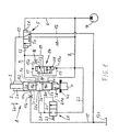
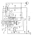
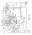
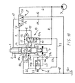
- the percussion generally designated 1 with automatic Hubumscnies has, in addition to the still to be described lines and drive and Control elements on a working cylinder 2, in which a percussion piston 3 is held in the longitudinal direction back and forth. This has in the interior of the working cylinder lying on two piston collars 3a and 3b, which are separated by a circumferential groove 3c.
- the percussion piston 3 passes into a piston tip 3d, which is opposite a tool in the form of a chisel 4; whose range of motion in the direction of the percussion piston 3 is limited by a stop 4a.
- the movement of the percussion piston 3 in the direction of the working stroke is indicated by an arrow 3e.
- the illustration in question shows the striking mechanism in a state when impact piston 3 strikes chisel 4. Normal operation is assumed, ie. the chisel does not penetrate into the material to be shredded and the percussion piston accordingly assumes the intended, normal service position.
- the control for the switching of the movement of the percussion piston 3 consists of a movable in a control valve 5 spool 5a, the smaller slide surface S1 via a reset line 6 constantly with the working pressure (system pressure) is applied; This is generated by an energy source in the form of a hydraulic pump 7. Also, the smaller piston area A1 is constantly acted upon by a pressure line 8, which is in communication with the return line 6, with the working pressure.
- the junction 8a of the pressure line is arranged with respect to the working cylinder 2 such that it lies in each case outside of the piston collar 3b and thus within the front cylinder chamber portion 2b.
- the larger slide surface S2 of the spool 5a is connected via a reversing line 9 with the interior of the working cylinder 2 in such a way that their junction 9a in the illustrated state via the circumferential groove 3c to a depressurized Return line 10 is connected.
- the junction 9a and the junction 10a of the return line are thus - seen in the longitudinal direction of the percussion piston 3 - in a distance opposite, which is smaller than the axial length of the circumferential groove 3c.
- the control valve 5 is connected on the one hand via a control line 11 to the pressure line 8 and on the other hand via a drain line 12 together with the tank 12a to the return line 10. Furthermore, the control valve 5 is connected via an alternating pressure line 13 with the rear cylinder chamber portion 2a in connection, via which the larger piston area A2 may optionally be acted upon by working pressure.
- the control valve can take two valve positions, namely the illustrated (right) scrubhub ein in which the larger piston area A2 via the alternating pressure line 13 and the discharge line 12 is relieved of pressure, and the (left) working stroke position in which the rear cylinder space portion 2a via the pressure line 8, the associated with this control line 11 and the alternating pressure line 13 is acted upon by the working pressure. This state has the consequence that the percussion piston 3 - executes a working stroke in the direction of arrow 3e, contrary to the restoring force emanating from the smaller piston surface A1.
- the impact mechanism 1 is further equipped with a pilot control in the form of a pilot valve 14, which can take either the illustrated (upper) blocking position or a (lower) open position.
- the position of the pilot valve can be influenced by two surfaces, namely on the smaller dimensioned Verstell materials V1 and the larger Verstell requirements V2.
- the latter is connected via a pilot line 15 with the interior of the working cylinder 2 in connection, the junction 15a - seen in the direction of the working stroke (arrow 3e) - behind the junction 9a of the reversing line 9.
- the pilot control line 15 in turn is connected to the pilot valve 14 on the output side via a pilot control branch line 15 b equipped with an orifice 16.
- the smaller adjustment surface V1 is connected via a pilot control return line 17a to the pressure line 8 and constantly applied to this with the working pressure; Accordingly, the pilot valve 14, under the action of the restoring force acting on the adjustment surface V1, tends to assume the open position (not shown).
- the pilot valve On the input side, the pilot valve is connected on the one hand via a short stroke line 18 with junction 18a to the interior of the working cylinder 2 and on the other hand via a pilot pressure line 17 to the pressure line 8.
- the junction 18a of the short-stroke line 18 is-again in the direction of the working stroke (arrow 3e) -disposed behind the junction 15a of the pilot control line 15.
- the pilot valve 14 on the one hand - as already mentioned - connected via the pilot control branch line 15b to the pilot control line 15 and on the other hand via an additional line 19 with the reversing line 9 for the control valve 5 in connection.
- the pilot pressure line 17 is connected to the pilot control line 15 via the pilot control branch line 15b and thereby generates an adjusting force effective in the direction of the blocking position, namely via the larger adjusting surface V2. Furthermore, in the illustrated blocking position, the short-stroke line 18 and the additional line 19 are blocked in the direction of the pilot valve 14.
- the (lower) open position of the pilot valve 14 is characterized in that the Kurzhub effet 18 is simultaneously with the pilot control branch line 15b and the additional line 19 in communication and that the pilot pressure line 17 is blocked.
- either the pressure conditions in the lines 15, 15b, 19 and 18 or only the pressure conditions in the lines 15, 15b and 19 can be adapted to one another. The latter is the case, if - as shown - the junction 18a of the short stroke is blocked by the piston collar 3b against the interior of the working cylinder 2.
- the striking mechanism works as follows: After switching the control valve 5 in the (left) working stroke position sets - after reaching the upper reversal point - the movement of the percussion piston in the direction of the working stroke (arrow 3e).
- the pilot valve 14 assumes the blocking position shown and is held by pressurization by means of the pilot pressure line 17 in this blocking position (since the working pressure is applied to both Verstellcite V1 and V2).
- the described embodiment thus makes it possible to react with each single stroke of the percussion piston on the properties or behavior of the material to be comminuted. If the tool penetrates into the material to be crushed, the percussion piston performs only a small stroke, so that the single impact energy is low. If the tool does not penetrate into the material to be shredded, a large stroke is carried out with correspondingly maximum single impact energy. Since - depending on the working conditions - in spite of the described automatic Hubumscnies clearances of the percussion piston 3 and thus unfavorable stress on the percussion mechanism can not be avoided, this is still equipped with an automatically switching Leerschlagtechnisch.
- the interior of the working cylinder 2 additionally has an idle connection 20a, which is preceded by a reversible securing element in the form of an automatically controlled 2/2-way valve 21 with the interposition of an idling line 20; whose input side is connected via an intermediate line 22 to the pressure line 8 in connection and is therefore constantly subjected to the working pressure.
- the 2/2-way valve is - against the action of a provision 23 in the form of a spring element - between two end positions - namely the (left) inoperative position and the (right) active position - switchable and has a position influencing its control surface 21a; This can be done via a to the
- the connection between the intermediate line 22 (and thus the pressure line 8) and the idle line 20 is interrupted, is located in the (right) active position of the outgoing of the pressure line 8 working pressure with the interposition of the dummy line 20 in the signal line 24 at so that the 2/2-way valve 21, under the action of the force acting from its control surface 21a Wirkouskraft maintains the once occupied active position.
- the idle connection 20a is arranged separately from the connection 18a of the short-stroke line 18. Accordingly, the idle protection can be effective regardless of the circumstances in the long-stroke or short-stroke operation, if the percussion piston 3 has crossed over the normal Aufschlag too by a predetermined distance to take a blanking position.
- the percussion piston assumes the normal Aufschlag too in the representation, the Leerschlag-confluence 20a is closed by the smaller piston surface A1 having the front piston collar 3b in the direction of the interior of the working cylinder 2. If the percussion piston in working stroke direction (arrow 3e) is extended so far that the Leerschlag-confluence 20a is no longer closed by the front piston collar 3b, the voltage applied to her working pressure with the interposition of the annular groove 3c and the control line 9 on the larger slide surface S2 of the spool 5a act, so that the controller 5 is held in the existing during the Arboitshubs (left) working stroke position.
- the return line 10 has a correspondingly sized outflow resistance, which is indicated by a throttle unit 10b.
- the controller 5 is prevented from switching from the working stroke to the (right) return stroke position under the action of the working pressure from the idling port 20a, whereby the striking piston 3 is stopped.
- the Leertschfeldfeld can be ineffectual switch in a simple manner, that the 2/2-way valve 21 is transferred to its (left) inoperative position, by switching off the outgoing of the pressure line 8 working pressure.
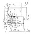
- Fig. 1 can the Leertschêt (2/2-way valve 21) also come in connection with differently designed percussive used, for example, in connection with the percussion designs according to Fig. 2 or 3
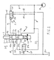
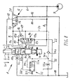
- the embodiment according to Fig. 2 differs thereby from the embodiment according to Fig. 1 in that no self-acting feedforward control in the form of a pilot control valve 14 is present. Accordingly, in the present embodiment, the lines 15, 15b, 17, 17a, 18 and 19 together with junctions 15a, 18a and the aperture 15b associated with the aperture 16 are missing. Also in this case takes the spool 5a of the control valve 5 - depending on the pressure conditions in the Um Taverntechnisch 9 - either the illustrated return stroke position (right) or the working stroke position (left).
- the control line 9 is applied after passing the piston collar 3b in the direction of the working stroke (arrow 3e) on the blank line 20 with working pressure, so that the controller 5 (as already based on Fig. 1 explained) in the during the working stroke recorded at work.
- the construction of a sufficiently high pressure in the control line 9 is thereby ensured that the return line 10 has a suitably sized discharge resistance (throttle unit 10b).
- control 5 is associated with a reversing valve 14A, which can be moved arbitrarily (expediently remotely operated) between two end positions, namely the illustrated blocking position and an open position.
- the reversing valve 14A is connected on the one hand via a short-stroke line 18 together with the mouth 18a to the interior of the working cylinder 2 and on the other hand via an additional line 19 to the reversing line 9.
- the reversing valve 14A exerts no influence on the position of the control slide 5a of the controller 5. If the reversing valve 14A assumes the (lower) open position, on the other hand-depending on the position of the percussion piston 3 within the working cylinder 2-between the interior thereof and the reversing line 9, a connection can be made, optionally an adjustment of the control slide 5a in the (left ) Workhub too has the consequence.
- the reversing line 9 is only then applied with a sufficiently high pressure, after the piston collar 3 b of the percussion piston 3 moved in the working stroke direction has released the junction 20 a of the idle line 20; Due to the then prevailing pressure conditions, the spool 5a can not switch to the (illustrated) return stroke, so that the hammer mechanism 1 is stopped.
- the 2/2-way valve 21 forming the securing element initially assumes the illustrated (left) inoperative position under the action of its return 23 when the percussion mechanism 1 is put into operation by being exposed to the working pressure and is therefore ineffective. Only delayed to start the percussion the 2/2-way valve 21 is thereby transferred to its operative position that the front Piston collar 3b in the course of the return stroke of the percussion piston 1, the Leerschlag-mouth 20a releases and thereby connects them via the front cylinder space portion 2b with the pressure line 8. After switching to the (right) operative position this is maintained as long as the lines 8, 22, 20 and 24 are acted upon by the working pressure.
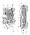
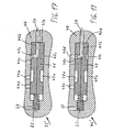
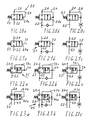
- FIG. 4 schematically illustrated 2/2-way valve 21 'has within a housing 25 a hollow cylinder 26, each with a plurality of transverse bores 26a and grooves 26b, wherein the hollow cylinder is fixed by means of a bolted to the housing threaded bolt 27 with respect to the housing 25 and sealed against the environment.
- the hollow cylinder 26 is connected via the transverse bores 26a and grooves 26b to the acted upon by the intermediate pressure intermediate line 22 and to a pressure-relieved leakage line 28; the latter can also be connected to the return line 10.
- a valve piston 29 is movably guided, which is supported on the right side of the serving as a provision, biased spring element 23 and under the action - in the illustrated inoperative position - rests with its control surface 21a on the housing 25.
- the valve piston 29 On the left side in the drawing, the valve piston 29 has a central bore 29a cooperating with the idle line 20 and transverse bores 29b connected thereto.
- the 2/2-way valve 21 ' according to Fig. 1 to 3 in that the control surface 21a is connected directly to the idle line 20 and thus the in Fig. 1 to 3 illustrated signal line 24 is not present.
- the valve piston 29 shifts to the right, as a result of the restoring force coming from the spring element 23, whereby a connection between the lines 20, 29b and 26a is established and 22 is produced; the 2/2-way valve 21 'thus takes its basis of the Fig. 1 to 3 explained active position.
- the 2/2-way valve 21 ' can be switched back into its inoperative position in a simple manner, that the present in the empty line 20 pressure level - as already explained before - is lowered by switching off the percussion.
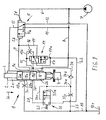
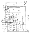
- Fig. 5 illustrated embodiment differs from that Fig. 1 in that the serving as a fuse element 2/2-way valve 21 is connected via a control surface 21 a acting on its signal line 30 to the alternating pressure line 13. This in turn communicates with the rear cylinder space portion 2a and acts on the larger piston area A2 with the working pressure as long as the control valve 5 occupies the not shown (left) working stroke position and thus a connection between the lines 13 and 8 is present.
- the present embodiment has the consequence that the 2/2-way valve 21 time-delayed for commissioning of the impact mechanism 1 is first transferred to its not shown (right) operative position as soon as the control valve 5 has taken his (left) working stroke position and the signal line 30th is also acted upon by the alternating pressure line 13 with the working pressure. Accordingly, the 2/2-way valve 21 moves under the action of acting on the control surface 21a Wirkouskraft in the illustration to the left, with the result that between the lines 22 and 20, a connection is made.
- the 2/2-way valve 21 will maintain its operative position substantially only as long as long as the working pressure is applied in the alternating pressure line 13.
- the function of the 2/2-way valve 21 as an emergency stop is not questioned, since this is at least always effective, when the percussion piston 3 is driven in the working stroke and thus could occur in itself lapses.
- appropriate structural design of the 2/2-way valve 21 can be taken to ensure that this once occupied active position - even with insufficient pressurization of the signal line 30 during the return stroke of the percussion piston 3 - as long as, until in the alternating pressure line 13 again the working pressure is applied and triggers the Wirkouskraft via the control surface 21a.
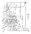
- FIG. 6 A particularly simple way of execution of the basis of the Fig. 5 explained 2/2-way valve 21 is in Fig. 6 shown.
- a valve piston 32 is movably guided in the longitudinal direction within a housing 31, which is supported on the left side on a likewise arranged in the housing 31 spring element 23.
- the area occupied by the spring element 23 is in turn held relieved of pressure by a leakage line 28.
- valve piston 32 rests against the housing 31 with its control surface 21a facing the signal line 30. This has spaced apart juxtaposed - two holes 31a and 31b, with the intermediate line 22 and with the blank line 20 (see, for example Fig. 1 ) keep in touch.
- the bore 31a is disposed relative to the valve piston 32 so as to communicate with the annular groove 32a in the illustrated inoperative position while the bore 31b is blocked by the valve piston.
- valve piston 32 moves against the return action of the spring member 23 to the left in the operative position with the result that via the annular groove 32 a connection between the holes 31 a and 31 b - and thus between the lines 22nd and 20 (cf Fig. 5 )-will be produced.
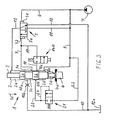
- the fuse element is designed as a 3/2-way valve 33 and connected via an acting on its control surface 33a signal line 34 to the previously described alternating pressure line 13.
- the 3/2-way valve 33 is the input side to the intermediate line 22 in connection, which in turn merges into the pressure line 8.
- the 3/2-way valve 33 is connected on the one hand to the blank line 20 and on the other hand via a line part 34 c to the signal line 34.
- the signal line 34 is in addition to the 3/2-way valve 33 in addition to a throttle line 35 in connection, which merges with the interposition of a throttle element 35a in the return line 10.
- the connection point 34a between the lines 34 and 35 is preceded by a spring-loaded check valve 34b, which blocks the signal line 34 in the direction of the alternating pressure line 13.
- connection between the lines 22 and 20 is interrupted and only the control surface 33 a is connected to the signal line 34.
- control surface 33 a is connected to the signal line 34.
- operative position of the 3/2-way valve 33 is both the empty line 20 and the signal line 34 via its line part 34c with the intermediate line 22 in connection.
- the 3/2-way valve 33 is transferred via the then acting on its control surface 33 a Wirk einskraft - against the restoring action of the spring element 23 - in the (right) operative position with the result that subsequently also the Lines 20, 34c are acted upon accordingly and thus the 3/2-way valve 33 its first occupied active position - regardless of subsequent changes of Pressure levels in the alternating pressure line 13 - maintains; the signal line 34 is thereby blocked by the check valve 34b in the direction of the alternating pressure line 13, while the existing pressure level is maintained via the throttle element 35a in the line part 34c and on the control surface 33a. If the striking mechanism 1 is stopped by switching off the working pressure, the line part 34c and the control surface 33a can be depressurized via the throttle element 35a, so that the 3/2-way valve 33 switches back to its illustrated inoperative position.
- the 3/2-way valve 33 in question is thus designed and connected so that it is transferred depending on the pressure level in the signal line 34 in its operative position and this then retains, as long as the percussion 1 is by maintaining the working pressure in the operating state.
- the Leertschêt is thereby delayed in time for commissioning of the percussion enabled by the fact that the alternating pressure line 13 is acted upon switching the control valve 5 in the (left) working stroke with the working pressure and thus the percussion piston 3 in the direction of the power stroke (arrow 3e) drives.
- the operation of the 3/2-way valve 33 can be made dependent on the fact that the signal line is connected to other Schlagwerk lines following the spring-loaded check valve 34b.
- the signal line 34 is connected to the reversing line 9, via which the position of the control valve 5 is influenced.
- the 3/2-way valve 33 switches to the (right) active position, if the reversing line 9 is acted upon by the working pressure and thus the control valve 5 is transferred to initiate the working stroke of the Schlaqkolbens 3 in its (left) working stroke position.
- the signal line 34 is connected to the Kurzhub für 18 following the spring-loaded check valve 34b.
- the 3/2-way valve 33 is transferred to its (right) operative position as soon as the working pressure is applied to the short-stroke line 18 for the first time.
- FIG. 10 shows an embodiment of the subject invention, in which the 3/2-way valve 33 associated signal line 34 is connected via an additional bore 34d with the interior of the working cylinder 2 in connection.
- the additional bore 34d is arranged such that it - as seen in the return stroke of the percussion piston 3 - opens before the blank-opening 20a of the blank line 20 in the interior.
- the line part 34c of the signal line 34 is in the direction of the additional bore 34d downstream of a spring-loaded check valve 34e, which blocks in the direction of the additional bore. Following the section of the signal line 34, via which the control surface 33a can be acted upon, the signal line 34 transitions into the previously described throttle line 35 at the connection point 34a.
- the check valve 34e serves to block the preceding sections of the signal line 34 against the interior of the working cylinder 2, if the 3/2-way valve 33 has been transferred to the (right) operative position and thus in the conduit part 34c and on the control surface 33a the working pressure is applied.
- the aforementioned position of the additional bore 34d has the consequence that the 3/2-way valve 33 already switches to the operative position before the front piston collar 3b, the blank-opening 20a of the idle line 20 releases.
- the subject invention can also be designed such that the fluidically connected to the control surface 33a of the 3/2-way valve 33 portion of the signal line 34 is connected to a signal source which the control surface after commissioning of the impact mechanism 1 either continuously or discontinuously per unit time or stepwise respectively supplies a limited control volume, under the action of which the 3/2-way valve 33 is transferred only delayed to the commissioning of the impact mechanism in the operative position.
- the signal line 34 via a equipped with a throttle element 36 branch 34f connected to the acted upon by the working pressure intermediate line 22.
- the junction 34a between the signal line 34 and the branch line 34f also communicates with a relief line 37 which is also connected to the intermediate line 22 and provided with a spring-loaded check valve 37a; the latter blocks the discharge line 37 in the direction of the signal line 34 and the branch line 34f.
- the signal line 34 is supplied under the action of the throttle element 36 per unit time, a limited control volume with the result that the control surface acting on the control surface 33a continuously increases control and the 3/2-way valve 33 gradually transferred to the (right) operative position , This is then maintained as long as the percussion mechanism 1 is in the operating state, ie is acted upon by the working pressure.
- the relief line 37 serves to relieve the signal line 34 after switching off the working pressure as soon as possible by the fact that the control surface 33a under the action of the spring element 23 outgoing restoring force fluid in the direction of the intermediate line 22 ausschiebt and the 3/2-way valve 33 thus again the can take shown inoperative position.
- the subject of the invention may also be designed such that the discharge line 37 together with the check valve 37a is omitted;
- the control surface 33a in a similar manner fluid in the direction of the branch line 34f and the intermediate line 22 push out, so that the 3/2-way valve 33 can switch back to its illustrated inoperative position.
- Fig. 12 corresponds functionally to those after Fig. 11 with the proviso that the connection point 34a between the control line 34 and the branch line 34f is connected to a throttle line 38, which is also equipped with a throttle element 38a and in turn opens into the return line 10.
- the throttle element 36 of the branch line 34f has a larger passage cross-section than the throttle element 38a of the throttle line 38.
- control surface 33a is supplied with a limited control volume via the signal line 34 per unit time; this corresponds to the difference between the introduced through the throttle element 36 and the discharged via the throttle element 38a volume.
- This embodiment also makes it possible, depending on the duty cycle of the percussion mechanism 1 in the signal line 34 to build up gradually after the throttle element 36, a control volume which continuously displaces the control surface 33a per unit time and thus the 3/2-way valve 33 - opposite the effect of the spring element 23 - finally switches to the (right) operative position; this is then maintained as long as long as in the intermediate line 22 of the striking mechanism acting on working pressure is applied.
- the Schlagtechnik 1 can - as in Fig. 13 shown - also be designed such that the flow-technically connected to the control surface 33a portion of the signal line 34 is connected with the interposition of a throttle element 39 to a percussion line in which, depending on the operating state of the percussion only temporarily applies the working pressure; Consequently, the control surface 33a is gradually displaced so long over several successive cycles of motion of the percussion piston 3 until finally the 3/2-way valve 33 - starting from the illustrated inoperative position - reaches the (right) operative position.
- the signal line is connected to the only temporarily acted upon by the working pressure alternating pressure line 13 and has, in addition to the throttle element 39, a spring-loaded check valve 40 which blocks in the direction of the alternating pressure line 13. Regardless of the position of the components 39 and 40 to each other is the check valve 40 - in the direction of the 3/2-way valve 33 - which already on the basis of Fig. 11 explained, in the intermediate line 22 opening discharge line 37 downstream.
- the junction between the lines 34 and 37 is again denoted by 34 a.
- control surface 33a is supplied in each case a limited control volume, as long as in the alternating pressure line 13th the working pressure is applied;
- the check valve 37a of the discharge line 37 assumes the blocking position under the action of the working pressure prevailing in the intermediate line 22. If the control surface 33a has been supplied a sufficient control volume in the course of several successive time cycles, the 3/2-way valve 33 finally switches to the (right) operative position, with the result that the empty line 20 and the signal line 34 also applied to the working pressure are and the check valve 40 blocks in the direction of the alternating pressure line 13. Accordingly, the 3/2-way valve 33 then remains in the active position once occupied, as long as the working pressure in the intermediate line 22 is applied. After switching off the working pressure, the 3/2-way valve 33 is relieved via the discharge line 37 with the result that the 3/2-way valve 33 switches back under the action of the spring element 23 in the illustrated (left) inoperative position.
- the last-described embodiment can - be changed to the effect that the signal line 34 - in accordance with otherwise unchanged configuration Fig. 8 - to the Um Kunststoff Kunststoff 9 or - based on Fig. 9 - Is connected to the Kurzhub für 18.
- These percussion lines are also only temporarily subjected to the working pressure and can be used in conjunction with the appropriately equipped lines 34 and 37 to the required for the displacement of the control surface 33 a and thus for the switching of the 3/2-way valve 33 control volume build up stepwise in the course of several successive movement cycles of the percussion piston 3.
- the subject invention may also be designed such that the signal line 34 is connected directly to the rear cylinder space portion 2a, so not with the interposition of the alternating pressure line 13th
- Fig. 14 shows a further variant of the subject invention, with which can be supplied to the control surface 33a stepwise in the course of several successive movement cycles required for the switching of the 3/2-way valve 33 volume.
- the signal line 34 connected to the idle line 20 is - as seen following the idle line 20 and in the direction of the junction 34a with the relief line 37 - likewise equipped with a throttle element 39 and a spring-loaded check valve 40. Accordingly, the control surface 33a of the 3/2-way valve 33 is supplied only a short time a limited control volume, if the front piston collar 3b, the Leerschlag-mouth 20a releases in the course of the return stroke of the percussion piston 3 and thereby applied via the front cylinder chamber portion 2b with the working pressure.
- the discharge line 37 is blocked via its check valve 37a in the direction of the connection point 34a and the signal line 34, as long as in the intermediate line 22, the working pressure prevails.
- the embodiment according to Fig. 15 differs from the previously described, the signal line 34 is separated from the Leerschlag-confluence 20 a with the interior of the working cylinder 2 in conjunction; its junction 34g is arranged with respect to the working cylinder 2 such that it - seen in the return stroke of the percussion piston 3 - between the junction 18a of the short-stroke line 18 and the junction 9a of the reversing line 9. Also in this case, the control volume acting on the control surface 33a is gradually increased as soon as the front piston collar 3b in the course of the return stroke of the percussion piston 3 respectively releases the confluence 34g exposing it to the working pressure prevailing there via the front cylinder space portion 2b.
- Pump 41 are constructed stepwise.
- the pump 41 is connected on the input side via a suction line 42 to the pressure-relieved discharge line 12 and the output side connected on the one hand to the discharge line 37 and on the other hand to the signal line 34.
- the pump 41 is connected via a drive line 43 with the reversing line 9 in connection. Accordingly, the pump 41 is only driven in each case, if the reversing line 9 is acted upon by the working pressure, and leads the control surface 33 a per cycle of the striking mechanism 1 each a constant volume. To avoid undesirable stress or an undesirable operating state, the pump 41 is internally equipped with a non-illustrated check valve, which prevents backflow against the conveyor.
- the pump 41 may be connected in the context of the invention via its drive line 43 to another percussion line, which is only temporarily acted upon by the working pressure.
- the drive line 43 of the pump 41 in particular also either with the alternating pressure line 13 (FIG. Fig. 7 ) or with the short-stroke line 18 ( Fig. 9 ) keep in touch.
- a metering valve which is controlled via a suitable Schlagtechnik line, in particular the Schlagtechnik lines 9, 13 or 18 and the control surface 33a at intervals in each case only a limited control volume supplies; the metering valve is - differently from the circuit of the pump 41-input connected to the intermediate line 22.
- Fig. 17 shows a variant of a serving as a fuse element two-position valve 33 '.
- This has a valve piston 45 movably guided in a housing 44 with a spring element 23 serving as a return and a leakage line 28 (cf. Fig. 6 ).
- Three bores 44a, 44h and 44c are arranged in the housing, each spaced apart from one another, the bores 44a and 44c communicating with the intermediate duct 22 and the bore 44b with the idle duct 20; Via the signal line 34, the control surface 33a on the spring element 23 opposite side of the valve piston 45 can be pressurized.
- the bore 44a communicates with an annular groove 45a in the valve piston 45 in connection.
- This is also provided with a central bore 45b extending from its control surface 33a equipped, which also merges into a (shorter) annular groove 45c in the valve piston 45.
- the center hole 45b represents the partial line 34c shown in the circuit diagrams.
- the control surface 33a is supported under the action of the spring element 23 in the direction of the signal line 34 on the housing 44, wherein the holes 44a to 44c are blocked by the valve piston 45 and its annular groove 45a. If acting on the control surface 33a of the voltage applied in the signal line 34 working pressure, the valve piston 45 moves within the housing 44 against the action of the spring member 23 to the left in the operative position; in this one hand, the holes 44a and 44b via the annular groove 45a and on the other hand, the control surface 33a and the bore 44c via the annular groove 45c and the central bore 45b connected to each other.
- the fuse element can - as out Fig. 18 visible - be designed as a 4/2-way valve 46.
- said fuse element On the input side, said fuse element is connected on the one hand to the intermediate line 22 and on the other hand to a signal line 47, which in turn communicates via its junction 47a with the interior of the working cylinder 2.
- the junction 47a is (as already indicated by the Fig. 15 explained) is arranged separately from the Leerschlag-confluence 20a of the blank line 20 and takes with respect to the working cylinder 2, a position between the opening 18a of the short-stroke line 18 and the junction 9a of the reversing line 9 a.
- the 4/2-way valve 46 is connected on the one hand to the already mentioned Leerschlagtechnisch and on the other hand to the line part 47b of the signal line 47, via which the control surface 46a of the 4/2-way valve can be acted upon by the pressure prevailing in the line part 47b pressure level.
- the conduit part 47b merges at a connection point 47c into the previously described relief line 37, which is connected to the intermediate line 22 and equipped with a spring-loaded check valve 37a which locks in the direction of the connection point 47c.
- the 4/2-way valve 46 takes under the action of its spring element 23 outgoing restoring force the inoperative position, in which on the one hand the connection between the lines 22 and 20 interrupted and on the other hand, a connection between the junction 47 a, the conduit part 47 b and the Control surface 46a is present.
- the lines 20 and 47b and the control surface 46a are acted upon via the intermediate line 22 with the working pressure while the connection between the junction 47a and the line part 47b is blocked.
- the signal line 47 is connected via its junction 47a, the front cylinder space section 2b and the intermediate line 22 to the pressure line 8 with the result that via the line part 47b also acts on the control surface 46a of the working pressure and the 4/2-way valve 46 - against the action of the spring element 23 - is transferred to the (right) operative position. This is then maintained as long as long as in the intermediate line 22, the working pressure is applied.
- the 4/2-way valve 46 can switch back to its illustrated inoperative position after the working pressure has been switched off; In this case, the line part 47b, together with the control surface 46a, is relieved via the check valve 37a in the direction of the intermediate line 22.
- the 4/2-way valve 46 can be used in the context of the invention also in cooperation with a signal line whose junction 47a occupies a different position or independently with respect to the working cylinder from the interior of the working cylinder 2 - is connected to a suitable Schlagtechnik line, in particular to the alternating pressure line 13, the Um Taverntechnisch 9 or the Kurzhub effet 18.
- a suitable Schlagtechnik line in particular to the alternating pressure line 13, the Um Taverntechnisch 9 or the Kurzhub effet 18.
- Fig. 19 - which refers to a variant of the 4/2-way valve - has the multi-position valve 46 'shown here in a housing 48 movably guided valve piston 49; this is supported on the left side of the previously mentioned spring element 23, which is held by the leakage line 28 depressurized.
- the bore 48a opens into a arranged on the valve piston 49 annular groove 49a; this is on the opposite side of the spring element 23 equipped with an outgoing from its control surface 46a a central bore 49b, which merges into another, angeodnete on the valve piston annular groove 49c.
- the control surface 46a may, as already mentioned, be acted upon by the bore 48d connected to the signal line 47 and be displaced continuously or discontinuously in the direction of the spring element 23.
- the Fig. 20a, b, c to 23a, b, c show different switching arrangements of serving as a fuse element two-position valves, which can be used in the context of the inventive solution idea.
- the Fig. 20b, c to 23b, c refer to embodiments that additionally allow relief of the portion of the signal line over which the respective control surface can be acted upon.
- the discharge takes place either by means of a discharge line, which is connected with the interposition of a spring-loaded check valve with the pressure line under working pressure, or via a throttle line, which is held relieved of pressure following a throttle element.
- Fig. 20a to c the security element - such as in Fig. 1 shown - designed as a 2/2-way valve and controlled by a signal line 24 which is connected to the idle line 20 and acts on this on the control surface 21a.
- Fig. 21a to c relate to embodiments using a 2/2-way valve 21, which - as in example in Fig. 5 illustrated-one of the blank line 20 independent signal line 30 have.
- the signal line 34 has an additional line part 34c and may be connected to different areas of the working cylinder or with different percussion lines.
- the Fig. 23a to c refer to switching arrangements with a in Fig. 18 shown 4/2-way valve 46 and a signal line 47 which acts temporarily with the interposition of a line part 47b on the control surface 46a of the 4/2-way valve.
- the two-position valves 21, 33 and 46 respectively - at least also connected to the working pressure leading and connected to the pressure line 8 intermediate line 22.
- Relief of the fuse element by means of a discharge line ( Figs. 20b, 21b, 22b and 23b ) is also in Fig. 13 shown.
- the throttle line is connected to the associated throttle element (as in Fig. 7 shown) connected to the pressure-relieved return line of the hammer mechanism.
- the advantage achieved by the invention is, in particular, that the percussion is automatically protected with relatively little technical effort against blank spaces, wherein the fuse element is designed such that the percussion can start first with ineffective switched Leerschlag thesis.
Landscapes
- Engineering & Computer Science (AREA)
- Automation & Control Theory (AREA)
- Physics & Mathematics (AREA)
- Fluid Mechanics (AREA)
- Mechanical Engineering (AREA)
- Percussive Tools And Related Accessories (AREA)
- Fluid-Pressure Circuits (AREA)
Applications Claiming Priority (2)
| Application Number | Priority Date | Filing Date | Title |
|---|---|---|---|
| DE10123202A DE10123202A1 (de) | 2001-05-12 | 2001-05-12 | Verfahren und Vorrichtung zur Absicherung eines fluidbetriebenen Schlagwerks gegen Leerschläge |
| DE10123202 | 2001-05-12 |
Publications (2)
| Publication Number | Publication Date |
|---|---|
| EP1256419A1 EP1256419A1 (de) | 2002-11-13 |
| EP1256419B1 true EP1256419B1 (de) | 2009-04-15 |
Family
ID=7684592
Family Applications (1)
| Application Number | Title | Priority Date | Filing Date |
|---|---|---|---|
| EP02009176A Expired - Lifetime EP1256419B1 (de) | 2001-05-12 | 2002-04-25 | Verfahren und Vorrichtung zur Absicherung eines fluidbetriebenen Schlagwerks gegen Leerschläge |
Country Status (5)
| Country | Link |
|---|---|
| US (1) | US6672403B2 (enExample) |
| EP (1) | EP1256419B1 (enExample) |
| JP (1) | JP4118594B2 (enExample) |
| DE (2) | DE10123202A1 (enExample) |
| ES (1) | ES2325765T3 (enExample) |
Families Citing this family (22)
| Publication number | Priority date | Publication date | Assignee | Title |
|---|---|---|---|---|
| DE102004035289A1 (de) * | 2004-07-21 | 2006-02-16 | Kennametal Widia Gmbh & Co.Kg | Werkzeug |
| DE102004035306A1 (de) * | 2004-07-21 | 2006-03-16 | Atlas Copco Construction Tools Gmbh | Druckmittelbetriebene Schlagvorrichtung insbesondere Hydraulikhammer |
| SE528745C2 (sv) * | 2005-06-22 | 2007-02-06 | Atlas Copco Rock Drills Ab | Ventilanordning för slagverk och slagverk för bergborrmaskin |
| DE102005028918A1 (de) * | 2005-06-22 | 2006-12-28 | Wacker Construction Equipment Ag | Bohr- und/oder Schlaghammer mit Leerlaufsteuerung |
| US7896102B2 (en) * | 2006-02-21 | 2011-03-01 | Festo Ag & Co. Kg | Pneumatic drive system |
| FI123634B (fi) * | 2007-10-05 | 2013-08-30 | Sandvik Mining & Constr Oy | Kallionrikkomislaite, suojaventtiili sekä menetelmä kallionrikkomislaitteen käyttämiseksi |
| EP2262618B1 (en) * | 2008-03-31 | 2016-06-08 | Construction Tools PC AB | Percussion tool |
| KR101058181B1 (ko) | 2009-05-04 | 2011-08-22 | 대모 엔지니어링 주식회사 | 브레이커용 밸브 시스템 |
| US8939227B2 (en) | 2010-12-23 | 2015-01-27 | Caterpillar Inc. | Pressure protection valve for hydraulic tool |
| FR2983760B1 (fr) * | 2011-12-09 | 2014-08-15 | Montabert Roger | Procede de commutation de la course de frappe d'un piston de frappe d’un appareil a percussions |
| ITBA20120019A1 (it) * | 2012-03-21 | 2013-09-22 | Tecna Group Srl | Demolitore per escavatori con circuito idraulico ottimizzato |
| DE102012012297A1 (de) * | 2012-03-30 | 2013-10-02 | Atlas Copco Construction Tools Gmbh | Ventil |
| FR3007154B1 (fr) * | 2013-06-12 | 2015-06-05 | Montabert Roger | Procede de commande de l’energie d’impact d’un piston de frappe d’un appareil a percussions |
| SE537608C2 (sv) * | 2013-11-01 | 2015-07-28 | Tools Pc Ab Const | Pneumatisk slaganordning och förfarande vid pneumatisk slaganordning |
| US9701003B2 (en) | 2014-05-23 | 2017-07-11 | Caterpillar Inc. | Hydraulic hammer having delayed automatic shutoff |
| US20160221171A1 (en) * | 2015-02-02 | 2016-08-04 | Caterpillar Inc. | Hydraulic hammer having dual valve acceleration control system |
| KR101550899B1 (ko) * | 2015-07-23 | 2015-09-08 | 대모 엔지니어링 주식회사 | 2단 자동 행정을 갖는 유압 브레이커 |
| JP7210452B2 (ja) * | 2017-07-24 | 2023-01-23 | 古河ロックドリル株式会社 | 液圧式打撃装置 |
| CN109458365B (zh) * | 2018-12-24 | 2024-02-02 | 江苏徐工工程机械研究院有限公司 | 工程机械液压系统以及工程机械 |
| JP7359584B2 (ja) * | 2019-07-23 | 2023-10-11 | 古河ロックドリル株式会社 | 液圧式打撃装置 |
| JP7390940B2 (ja) * | 2020-03-12 | 2023-12-04 | 古河ロックドリル株式会社 | 液圧式打撃装置 |
| JP7431067B2 (ja) * | 2020-03-13 | 2024-02-14 | 古河ロックドリル株式会社 | 液圧式打撃装置 |
Family Cites Families (12)
| Publication number | Priority date | Publication date | Assignee | Title |
|---|---|---|---|---|
| US4026193A (en) * | 1974-09-19 | 1977-05-31 | Raymond International Inc. | Hydraulically driven hammer system |
| US5064005A (en) * | 1990-04-30 | 1991-11-12 | Caterpillar Inc. | Impact hammer and control arrangement therefor |
| US5474138A (en) * | 1993-12-08 | 1995-12-12 | J & M Hydraulics, Inc. | Hydraulic control circuit for pile driver |
| DE4343589C1 (de) * | 1993-12-21 | 1995-04-27 | Klemm Guenter | Fluidbetätigter Schlaghammer |
| DE19529538A1 (de) * | 1995-08-11 | 1997-02-13 | Delmag Maschinenfabrik | Ramme |
| WO1998004387A1 (en) * | 1996-07-25 | 1998-02-05 | Komatsu Ltd. | Hydraulically operated breaker with lost-motion prevention device |
| JPH1080878A (ja) | 1996-09-05 | 1998-03-31 | Furukawa Co Ltd | 液圧式打撃装置 |
| DE19636659C2 (de) * | 1996-09-10 | 2000-11-23 | Krupp Berco Bautechnik Gmbh | Fluidbetriebenes Schlagwerk mit automatischer Hubumschaltung |
| DE19803449A1 (de) * | 1998-01-30 | 1999-08-05 | Krupp Berco Bautechnik Gmbh | Druckmittelbetriebene Schlagvorrichtung |
| DE19804078A1 (de) * | 1998-02-03 | 1999-08-05 | Krupp Berco Bautechnik Gmbh | Fluidbetriebenes Schlagwerk |
| DE10013270A1 (de) * | 2000-03-17 | 2001-09-20 | Krupp Berco Bautechnik Gmbh | Fluidbetriebenes Schlagwerk |
| US6491114B1 (en) * | 2000-10-03 | 2002-12-10 | Npk Construction Equipment, Inc. | Slow start control for a hydraulic hammer |
-
2001
- 2001-05-12 DE DE10123202A patent/DE10123202A1/de not_active Withdrawn
-
2002
- 2002-04-25 ES ES02009176T patent/ES2325765T3/es not_active Expired - Lifetime
- 2002-04-25 DE DE50213438T patent/DE50213438D1/de not_active Expired - Lifetime
- 2002-04-25 EP EP02009176A patent/EP1256419B1/de not_active Expired - Lifetime
- 2002-04-30 US US10/134,442 patent/US6672403B2/en not_active Expired - Lifetime
- 2002-05-13 JP JP2002137661A patent/JP4118594B2/ja not_active Expired - Fee Related
Also Published As
| Publication number | Publication date |
|---|---|
| JP2003025251A (ja) | 2003-01-29 |
| DE10123202A1 (de) | 2002-11-14 |
| US20020185285A1 (en) | 2002-12-12 |
| DE50213438D1 (de) | 2009-05-28 |
| US6672403B2 (en) | 2004-01-06 |
| JP4118594B2 (ja) | 2008-07-16 |
| EP1256419A1 (de) | 2002-11-13 |
| ES2325765T3 (es) | 2009-09-16 |
Similar Documents
| Publication | Publication Date | Title |
|---|---|---|
| EP1256419B1 (de) | Verfahren und Vorrichtung zur Absicherung eines fluidbetriebenen Schlagwerks gegen Leerschläge | |
| EP1776212B1 (de) | Druckmittelbetriebene schlagvorrichtung, insbesondere hydraulikhammer | |
| DE10327132B4 (de) | Hydraulikschaltung für eine Ausleger-Zylinder-Kombination, welche eine Umlauffunktion aufweist | |
| EP1136189B1 (de) | Fluidbetriebenes Schlagwerk | |
| EP0827813B1 (de) | Fluidbetriebenes Schlagwerk mit automatischer Hubumschaltung | |
| DE2512731C2 (enExample) | ||
| DE69222493T2 (de) | Hydraulischer Schlaghammer | |
| DE69227925T2 (de) | Hydraulische pfahlramme | |
| DE202014001328U1 (de) | Schnellkuppler | |
| EP0934804B1 (de) | Druckmittelbetriebene Schlagvorrichtung | |
| DE2923229C2 (de) | Hydraulische Bohrmaschine zum Schlag- und Drehschlagbohren | |
| DE102005022275A1 (de) | Hydraulische Steueranordnung | |
| DE2461633B1 (de) | Hydraulische schlagvorrichtung | |
| DE1295383B (de) | Sicherheitseinrichtung fuer das Steuersystem eines hydraulischen Motors mit zwei synchron zu betaetigenden Hauptventilen und einem Fuehlerventil | |
| EP0672506B1 (de) | Hydraulischer Schlaghammer | |
| DE10237407B4 (de) | Hydraulischer Schlaghammer mit Leerschlagabschaltung | |
| DE19652079C2 (de) | Fluidbetriebenes Schlagwerk | |
| EP0778110A2 (de) | Verfahren zur Beeinflussung des Betriebsverhaltens eines fluidbetriebenen Schlagwerks und zur Durchführung des Verfahrens geeignetes Schlagwerk | |
| DE4338288A1 (de) | Druckmittelbetriebene Presse, insbesondere hydraulische Ösenpresse, zum Lochen von Bahnen und Setzen vondas Loch randseitig verstärkenden Ösen | |
| EP1711662B1 (de) | Hydraulische steueranordnung | |
| DE2454940C3 (de) | Schlaggerät | |
| DE19804078A1 (de) | Fluidbetriebenes Schlagwerk | |
| DE2327705A1 (de) | Vorrichtung zur steuerung einer druckmittelbetaetigten presse | |
| DE2850056C2 (de) | Hydraulische Steuerschaltung für hydraulisch angetriebene Arbeitsmaschinen wie Pressen, Scheren o.dgl. | |
| DE3145401A1 (de) | Druckuebersetzte kraftzylindereinheit |
Legal Events
| Date | Code | Title | Description |
|---|---|---|---|
| PUAI | Public reference made under article 153(3) epc to a published international application that has entered the european phase |
Free format text: ORIGINAL CODE: 0009012 |
|
| AK | Designated contracting states |
Kind code of ref document: A1 Designated state(s): AT BE CH CY DE DK ES FI FR GB GR IE IT LI LU MC NL PT SE TR |
|
| AX | Request for extension of the european patent |
Free format text: AL;LT;LV;MK;RO;SI |
|
| RAP1 | Party data changed (applicant data changed or rights of an application transferred) |
Owner name: ATLAS COPCO CONSTRUCTION TOOLS GMBH |
|
| AKX | Designation fees paid | ||
| 17P | Request for examination filed |
Effective date: 20030701 |
|
| RBV | Designated contracting states (corrected) |
Designated state(s): DE ES FI FR GB IT |
|
| REG | Reference to a national code |
Ref country code: DE Ref legal event code: 8566 |
|
| GRAP | Despatch of communication of intention to grant a patent |
Free format text: ORIGINAL CODE: EPIDOSNIGR1 |
|
| GRAS | Grant fee paid |
Free format text: ORIGINAL CODE: EPIDOSNIGR3 |
|
| GRAA | (expected) grant |
Free format text: ORIGINAL CODE: 0009210 |
|
| AK | Designated contracting states |
Kind code of ref document: B1 Designated state(s): DE ES FI FR GB IT |
|
| REG | Reference to a national code |
Ref country code: GB Ref legal event code: FG4D Free format text: NOT ENGLISH |
|
| REF | Corresponds to: |
Ref document number: 50213438 Country of ref document: DE Date of ref document: 20090528 Kind code of ref document: P |
|
| REG | Reference to a national code |
Ref country code: ES Ref legal event code: FG2A Ref document number: 2325765 Country of ref document: ES Kind code of ref document: T3 |
|
| PLBE | No opposition filed within time limit |
Free format text: ORIGINAL CODE: 0009261 |
|
| STAA | Information on the status of an ep patent application or granted ep patent |
Free format text: STATUS: NO OPPOSITION FILED WITHIN TIME LIMIT |
|
| 26N | No opposition filed |
Effective date: 20100118 |
|
| REG | Reference to a national code |
Ref country code: FR Ref legal event code: PLFP Year of fee payment: 15 |
|
| REG | Reference to a national code |
Ref country code: FR Ref legal event code: PLFP Year of fee payment: 16 |
|
| REG | Reference to a national code |
Ref country code: FR Ref legal event code: PLFP Year of fee payment: 17 |
|
| PGFP | Annual fee paid to national office [announced via postgrant information from national office to epo] |
Ref country code: DE Payment date: 20210428 Year of fee payment: 20 Ref country code: FI Payment date: 20210428 Year of fee payment: 20 Ref country code: FR Payment date: 20210426 Year of fee payment: 20 Ref country code: IT Payment date: 20210421 Year of fee payment: 20 |
|
| PGFP | Annual fee paid to national office [announced via postgrant information from national office to epo] |
Ref country code: GB Payment date: 20210427 Year of fee payment: 20 Ref country code: ES Payment date: 20210504 Year of fee payment: 20 |
|
| REG | Reference to a national code |
Ref country code: DE Ref legal event code: R071 Ref document number: 50213438 Country of ref document: DE |
|
| REG | Reference to a national code |
Ref country code: FI Ref legal event code: MAE |
|
| REG | Reference to a national code |
Ref country code: GB Ref legal event code: PE20 Expiry date: 20220424 |
|
| PG25 | Lapsed in a contracting state [announced via postgrant information from national office to epo] |
Ref country code: GB Free format text: LAPSE BECAUSE OF EXPIRATION OF PROTECTION Effective date: 20220424 |
|
| REG | Reference to a national code |
Ref country code: ES Ref legal event code: FD2A Effective date: 20220901 |
|
| PG25 | Lapsed in a contracting state [announced via postgrant information from national office to epo] |
Ref country code: ES Free format text: LAPSE BECAUSE OF EXPIRATION OF PROTECTION Effective date: 20220426 |