EP1256368A2 - Verfahren zur Abdichtung eines Siliziumnitridfilters und Zusammensetzung zur Abdichtung - Google Patents
Verfahren zur Abdichtung eines Siliziumnitridfilters und Zusammensetzung zur Abdichtung Download PDFInfo
- Publication number
- EP1256368A2 EP1256368A2 EP02009377A EP02009377A EP1256368A2 EP 1256368 A2 EP1256368 A2 EP 1256368A2 EP 02009377 A EP02009377 A EP 02009377A EP 02009377 A EP02009377 A EP 02009377A EP 1256368 A2 EP1256368 A2 EP 1256368A2
- Authority
- EP
- European Patent Office
- Prior art keywords
- sealing
- silicon nitride
- composition
- filter
- nitride filter
- Prior art date
- Legal status (The legal status is an assumption and is not a legal conclusion. Google has not performed a legal analysis and makes no representation as to the accuracy of the status listed.)
- Withdrawn
Links
Images


Classifications
-
- B—PERFORMING OPERATIONS; TRANSPORTING
- B28—WORKING CEMENT, CLAY, OR STONE
- B28B—SHAPING CLAY OR OTHER CERAMIC COMPOSITIONS; SHAPING SLAG; SHAPING MIXTURES CONTAINING CEMENTITIOUS MATERIAL, e.g. PLASTER
- B28B11/00—Apparatus or processes for treating or working the shaped or preshaped articles
- B28B11/003—Apparatus or processes for treating or working the shaped or preshaped articles the shaping of preshaped articles, e.g. by bending
- B28B11/006—Making hollow articles or partly closed articles
-
- B—PERFORMING OPERATIONS; TRANSPORTING
- B01—PHYSICAL OR CHEMICAL PROCESSES OR APPARATUS IN GENERAL
- B01D—SEPARATION
- B01D39/00—Filtering material for liquid or gaseous fluids
- B01D39/14—Other self-supporting filtering material ; Other filtering material
- B01D39/20—Other self-supporting filtering material ; Other filtering material of inorganic material, e.g. asbestos paper, metallic filtering material of non-woven wires
- B01D39/2068—Other inorganic materials, e.g. ceramics
- B01D39/2072—Other inorganic materials, e.g. ceramics the material being particulate or granular
- B01D39/2075—Other inorganic materials, e.g. ceramics the material being particulate or granular sintered or bonded by inorganic agents
-
- B—PERFORMING OPERATIONS; TRANSPORTING
- B01—PHYSICAL OR CHEMICAL PROCESSES OR APPARATUS IN GENERAL
- B01D—SEPARATION
- B01D46/00—Filters or filtering processes specially modified for separating dispersed particles from gases or vapours
- B01D46/24—Particle separators, e.g. dust precipitators, using rigid hollow filter bodies
- B01D46/2403—Particle separators, e.g. dust precipitators, using rigid hollow filter bodies characterised by the physical shape or structure of the filtering element
- B01D46/2418—Honeycomb filters
-
- C—CHEMISTRY; METALLURGY
- C04—CEMENTS; CONCRETE; ARTIFICIAL STONE; CERAMICS; REFRACTORIES
- C04B—LIME, MAGNESIA; SLAG; CEMENTS; COMPOSITIONS THEREOF, e.g. MORTARS, CONCRETE OR LIKE BUILDING MATERIALS; ARTIFICIAL STONE; CERAMICS; REFRACTORIES; TREATMENT OF NATURAL STONE
- C04B35/00—Shaped ceramic products characterised by their composition; Ceramics compositions; Processing powders of inorganic compounds preparatory to the manufacturing of ceramic products
- C04B35/515—Shaped ceramic products characterised by their composition; Ceramics compositions; Processing powders of inorganic compounds preparatory to the manufacturing of ceramic products based on non-oxide ceramics
- C04B35/58—Shaped ceramic products characterised by their composition; Ceramics compositions; Processing powders of inorganic compounds preparatory to the manufacturing of ceramic products based on non-oxide ceramics based on borides, nitrides, i.e. nitrides, oxynitrides, carbonitrides or oxycarbonitrides or silicides
- C04B35/584—Shaped ceramic products characterised by their composition; Ceramics compositions; Processing powders of inorganic compounds preparatory to the manufacturing of ceramic products based on non-oxide ceramics based on borides, nitrides, i.e. nitrides, oxynitrides, carbonitrides or oxycarbonitrides or silicides based on silicon nitride
- C04B35/591—Shaped ceramic products characterised by their composition; Ceramics compositions; Processing powders of inorganic compounds preparatory to the manufacturing of ceramic products based on non-oxide ceramics based on borides, nitrides, i.e. nitrides, oxynitrides, carbonitrides or oxycarbonitrides or silicides based on silicon nitride obtained by reaction sintering
-
- C—CHEMISTRY; METALLURGY
- C04—CEMENTS; CONCRETE; ARTIFICIAL STONE; CERAMICS; REFRACTORIES
- C04B—LIME, MAGNESIA; SLAG; CEMENTS; COMPOSITIONS THEREOF, e.g. MORTARS, CONCRETE OR LIKE BUILDING MATERIALS; ARTIFICIAL STONE; CERAMICS; REFRACTORIES; TREATMENT OF NATURAL STONE
- C04B35/00—Shaped ceramic products characterised by their composition; Ceramics compositions; Processing powders of inorganic compounds preparatory to the manufacturing of ceramic products
- C04B35/622—Forming processes; Processing powders of inorganic compounds preparatory to the manufacturing of ceramic products
- C04B35/626—Preparing or treating the powders individually or as batches ; preparing or treating macroscopic reinforcing agents for ceramic products, e.g. fibres; mechanical aspects section B
- C04B35/63—Preparing or treating the powders individually or as batches ; preparing or treating macroscopic reinforcing agents for ceramic products, e.g. fibres; mechanical aspects section B using additives specially adapted for forming the products, e.g.. binder binders
- C04B35/632—Organic additives
- C04B35/634—Polymers
- C04B35/63404—Polymers obtained by reactions only involving carbon-to-carbon unsaturated bonds
- C04B35/63416—Polyvinylalcohols [PVA]; Polyvinylacetates
-
- F—MECHANICAL ENGINEERING; LIGHTING; HEATING; WEAPONS; BLASTING
- F01—MACHINES OR ENGINES IN GENERAL; ENGINE PLANTS IN GENERAL; STEAM ENGINES
- F01N—GAS-FLOW SILENCERS OR EXHAUST APPARATUS FOR MACHINES OR ENGINES IN GENERAL; GAS-FLOW SILENCERS OR EXHAUST APPARATUS FOR INTERNAL-COMBUSTION ENGINES
- F01N3/00—Exhaust or silencing apparatus having means for purifying, rendering innocuous, or otherwise treating exhaust
- F01N3/02—Exhaust or silencing apparatus having means for purifying, rendering innocuous, or otherwise treating exhaust for cooling, or for removing solid constituents of, exhaust
- F01N3/021—Exhaust or silencing apparatus having means for purifying, rendering innocuous, or otherwise treating exhaust for cooling, or for removing solid constituents of, exhaust by means of filters
- F01N3/022—Exhaust or silencing apparatus having means for purifying, rendering innocuous, or otherwise treating exhaust for cooling, or for removing solid constituents of, exhaust by means of filters characterised by specially adapted filtering structure, e.g. honeycomb, mesh or fibrous
- F01N3/0222—Exhaust or silencing apparatus having means for purifying, rendering innocuous, or otherwise treating exhaust for cooling, or for removing solid constituents of, exhaust by means of filters characterised by specially adapted filtering structure, e.g. honeycomb, mesh or fibrous the structure being monolithic, e.g. honeycombs
-
- B—PERFORMING OPERATIONS; TRANSPORTING
- B01—PHYSICAL OR CHEMICAL PROCESSES OR APPARATUS IN GENERAL
- B01D—SEPARATION
- B01D2271/00—Sealings for filters specially adapted for separating dispersed particles from gases or vapours
- B01D2271/02—Gaskets, sealings
- B01D2271/025—Making of sealings
-
- Y—GENERAL TAGGING OF NEW TECHNOLOGICAL DEVELOPMENTS; GENERAL TAGGING OF CROSS-SECTIONAL TECHNOLOGIES SPANNING OVER SEVERAL SECTIONS OF THE IPC; TECHNICAL SUBJECTS COVERED BY FORMER USPC CROSS-REFERENCE ART COLLECTIONS [XRACs] AND DIGESTS
- Y02—TECHNOLOGIES OR APPLICATIONS FOR MITIGATION OR ADAPTATION AGAINST CLIMATE CHANGE
- Y02T—CLIMATE CHANGE MITIGATION TECHNOLOGIES RELATED TO TRANSPORTATION
- Y02T10/00—Road transport of goods or passengers
- Y02T10/10—Internal combustion engine [ICE] based vehicles
- Y02T10/12—Improving ICE efficiencies
Definitions
- the present invention relates to a method for sealing a silicon nitride filter having a generally columnar outer shape and having a plurality of through-holes mutually parallel to one another, extending between the opposing end surfaces, with which excellent air-tightness and durability can be obtained, and which is particularly suitable for a silicon nitride filter for diesel particulates, and a sealing composition to be used therefor.
- a ceramic filter is widely used as e.g. a filter for removing diesel particulates discharged from a diesel engine, a support for an exhaust gas clarification catalyst or a dust-proof filter in a high temperature gas.
- a silicon nitride filter has attracted an attention as a filter for removing diesel particulates in view of its excellent heat resistance, corrosion resistance and thermal shock resistance.
- a silicon nitride filter having a generally columnar outer shape and having a plurality of through-holes mutually parallel to one another, extending between the opposing end surfaces, is formed usually by e.g. extrusion.
- one end of the plurality of through-holes mutually parallel to one another, extending between the opposing end surfaces, is sealed and the other end is left open when the filter is used.
- a honeycomb filter consisting of a prism, a cylinder or an elliptic cylinder having a plurality of through-holes parallel to one another in a length direction may be mentioned.
- the filter end surface is sealed in a checkered pattern so that one end surface of each through-hole is sealed and the other end surface is left open.
- JP-A-57-7215 proposes a method of covering the end surfaces of the honeycomb body with a film, punching the film at a part to be sealed with a pinholder in a checkered pattern, and injecting a body or paste of the same material as the filter from the holes for sealing.
- the material of the same material as the sealed filter may undergo sintering in the heat treatment process and firing shrinkage may take place, whereby the injected part may open, or e.g. cracks may form on the wall at the sealed part, thus decreasing air-tightness.
- a predetermined part may not accurately be sealed due to e.g. breakage of the film or position slippage, or leavings from the film when punched with a pinhole may remain.
- JP-A-5-85865 proposes, in order to overcome the problem by firing shrinkage, a method wherein the particle size proportion of ceramic particles in a sealing material is based on coarse grains.
- the particle size proportion is based on coarse grains, although the firing shrinkage may be reduced, sintering may not adequately proceed and the strength of the sealing material itself may be inadequate, and the sealing material may be peeled off from the filter.
- JP-A-8-243329 proposes as a sealing material for a honeycomb containing silicon carbide as the main component, a mixture comprising silicon carbide, carbon and a silicon compound. With this method, the silicon compound and carbon are reacted and sintered to form silicon carbide, whereby the firing shrinkage is reduced, and the strength is sufficient.
- the sealing material can be used as a sealing material only for a silicon carbide filter. Further, the treatment temperature is so high as from 1,700 to 2,300°C, and production is difficult.
- the present invention provides a method for sealing a silicon nitride filter having a generally columnar outer shape and a plurality of through-holes mutually parallel to one another, extending between the opposing end surfaces, which comprises selectively packing a composition containing metal silicon particles in the vicinity of the opening of the through-holes to be sealed, subjecting the silicon nitride filter to a heat treatment in a nitrogen atmosphere so that the metal silicon particles contained in the composition are nitrided and formed into silicon nitride for sealing.
- the silicon nitride filter (hereinafter referred to simply as a filter) is not particularly limited so long as it is a porous filter having a generally columnar outer shape and having a plurality of through-holes mutually parallel to one another, extending between the opposing end surfaces, and containing at least 50 mass% (hereinafter referred to simply as %) of silicon nitride.
- the number of the end surfaces of the filter (hereinafter referred to simply as end surfaces) is usually two in the case of e.g. a honeycomb filter.
- a composition containing metal silicon particles as the main component is selectively packed in the vicinity of the opening of the through-holes to be sealed on the end surfaces, and the silicon nitride filter is subjected to a heat treatment in a nitrogen atmosphere so that the composition is nitrided and formed into silicon nitride for sealing.
- the metal silicon particles contained in the composition are not particularly limited, but preferred are high purity ones which are formed into silicon nitride having a high purity by a nitriding reaction, whereby excellent properties such as heat resistance can be obtained.
- the metal silicon particles more preferably have an average particle diameter of from 1 to 150 ⁇ m. If the average particle diameter is less than 1 ⁇ m, the metal silicon particles are likely to oxidize in the air, and on the other hand, if the average particle diameter exceeds 150 ⁇ m, the particles tend to be too large, whereby spaces are likely to form between the sealing material and the filter wall surface in the inside of the through-holes.
- the amount of the metal silicon particles is less than 70% in the solid content of the composition, shrinkage is likely to occur, such being unfavorable. On the other hand, if it exceed 98%, nitriding is less likely to be accelerated, such being unfavorable.
- the composition preferably contains oxide particles in addition to the metal silicon particles, whereby nitriding of the metal silicon particles is accelerated, and further, mechanical strength of the nitrided composition (hereinafter referred to simply as a sealing material) improves. It is more preferred that the composition contains from 70 to 98% of the metal silicon particles and from 2 to 30% of the oxide particles as the solid content.
- the oxide particles are not particularly limited, but preferably consist of at least one member selected from the group consisting of alumina, iron oxide, yttria, spinel, magnesia and ytterbium oxide.
- the oxide particles consist of alumina or iron oxide
- nitriding of the metal silicon particles is accelerated, and the nitriding temperature is decreased, such being preferred.
- the oxide particles consist of alumina such an advantage can be obtained that a part of the oxide particles react with silicon nitride to form a solid solution, thus increasing oxidation resistance.
- the average particle diameter of the oxide particles is preferably from 1 to 20 ⁇ m, whereby the effect can be obtained with a small amount.
- the amount of the oxide particles is less than 2% in the solid content of the composition, the effect by its addition is hardly be obtained stably, such being unfavorable.
- it exceeds 30% the coefficient of thermal expansion of the sealing material after nitriding tends to increase, and the thermal shock resistance tends to decrease, such being unfavorable.
- the composition when the composition is packed in the vicinity of the opening of the through-holes, the composition preferably contains a binder for molding and a solvent, whereby packing is easily be carried out.
- the binder for molding is not particularly limited so long as it is an organic binder to be used for ceramic molding, however, the lower the amount of carbon remaining after thermal decomposition, the better.
- Such an organic binder may, for example, be polyvinyl alcohol, polyvinyl acetate or methyl cellulose.
- the amount of the binder for molding is preferably from 2 to 5% by outer percentage based on the solid content of the composition excluding the binder for molding.
- the solvent may be water or an organic solvent such as an alcohol.
- the amount of the solvent is preferably from 20 to 80% by outer percentage based on the solid content of the composition.
- the method of packing the composition may, for example, be a dipping method wherein the filter is immersed in the composition containing a solvent, or a method wherein the composition is injected to a part of the filter to be sealed.
- Advantages such as a high productivity can be obtained when the dipping method is employed, which can easily be carried out.
- the composition may selectively be packed directly in the vicinity of the opening of the through-holes to be sealed, however, it is preferred to first pack a masking material in the vicinity of the opening of through-holes other than the through-holes to be sealed, i.e. the through-holes to be left open, whereby the composition can be packed all at once in the part to be sealed by the dipping method.
- the vicinity of the opening is within from about 20 to about 30 mm from the end surface.
- a masking material is packed in the opening of through-holes to be left open on the end surfaces first, then the composition is packed in the opening of through-holes to be sealed on the end surfaces, then the masking material is removed, and the entire filter having the composition alone packed therein is subjected to a heat treatment in a nitrogen atmosphere.
- the heat treatment the metal silicon particles in the composition packed in the end surfaces of the silicon nitride filter is directly nitrided and formed into silicon nitride.
- the masking material is not particularly limited so long as it is easily be packed in the through-holes and easily be removed from the through-holes after the object is achieved, however, preferred is an organic substance having a small amount of carbon remaining after the thermal decomposition, whereby the nitriding reaction is likely to proceed smoothly without carbonization of the metal silicon in the composition.
- the masking material is preferably an organic polymer, particularly preferably a thermoplastic polymer, as it is easily be packed in the through-holes and can easily be removed by e.g. thermal decomposition.
- a masking material may, for example, be methyl cellulose, polyethylene glycol, polyethylene oxide or paraffin. It is particularly preferred to employ polyethylene glycol as the masking material, as one having a melting point within a range of from room temperature to 90°C is easily available, and the solidification phenomenon can be utilized for packing of the masking material.
- a method of packing the masking material a method wherein a liquid masking material is put in a packing apparatus having an injection port which can go into the through-holes, and the liquid masking material is packed in every through-hole in the filter, followed by drying, or a method wherein a liquid masking material is put in a similar packing apparatus, the liquid masking material is packed in every through-hole in the filter which is held at a temperature lower than the melting point of the masking material so that the masking material is solidified substantially simultaneously with the packing, may, for example, be mentioned.
- a removal method by heat dissolution or an extraction method with a solvent may, for example, be mentioned.
- the removal method by heat dissolution is preferred since operation is easy and the productivity is high.
- the temperature-raising rate is from 100 to 600°C/h
- the holding temperature is from 300 to 800°C
- the holding time is from 1 to 10 hours
- the atmosphere is not particularly limited, but preferred is an air atmosphere or a nitrogen atmosphere.
- the composition contains metal silicon particles, and the metal silicon particles are subjected to a heat treatment in an atmosphere of nitrogen (hereinafter sometimes referred to as nitriding) and formed into silicon nitride, whereby substantially no firing shrinkage occurs, and decrease in air-tightness due to the firing shrinkage can be avoided.
- nitriding an atmosphere of nitrogen
- the holding temperature in the heat treatment is preferably from 1,100 to 1,800°C. If the holding temperature is less than 1,100°C, the nitriding reaction may not adequately proceed, and the metal silicon may remain to deteriorate heat resistance, such being unfavorable. On the other hand, if the holding temperature exceeds 1,800°C, decomposition of silicon nitride formed by the nitriding may begin, mechanical strength may decrease, and leakage of e.g. particulates from the filter may occur.
- the holding time in the heat treatment is preferably from 1 to 24 hours, particularly preferably from 4 to 12 hours. If the holding time is less than 1 hour, there is the possibility that the nitriding reaction may not adequately proceed. On the other hand, if the holding time exceeds 24 hours, the nitriding reaction hardly proceeds any more, and the productivity tends to decrease. Even in a process of temperature raising, if the temperature is within the specified range, the time passed will be included in the holding time.
- the temperature raising rate may suitably be selected depending upon e.g. the size or the shape of the filter, or the number of the filter to be subjected to a heat treatment, but it is preferably from 50 to 600°C/h, whereby the nitriding ratio tends to be high.
- the nitrogen atmosphere is an atmosphere containing substantially solely nitrogen without containing oxygen, but it may contain another inert gas.
- the nitrogen partial pressure in the nitrogen atmosphere is preferably at least 50 kPa.
- FIG. 1 A cylindrical honeycomb filter 1 having a diameter of 15 cm and a length of 15 cm, obtained by extrusion, was used.
- the size of through-holes 11 is 1.8x1.8x150 mm.
- Fig. 1 a longitudinal section illustrating the honeycomb filter 1 in a length direction.
- an injector 2 (volume: 200 cm 3 ) having an injection port 3 (outer diameter: 1.5 mm, inner diameter: 1 mm) smaller than the through-holes 11 was used as a masking packing apparatus.
- polyethylene glycol having a molecular weight of 10,000 (melting point: about 60°C) as the masking material 4 is contained.
- a predetermined amount of the polyethylene glycol was packed by pressing a piston 5. This operation is carried out with respect to all the parts 7 to be masked formed in a checkered pattern.
- the entire injector 2 is held at 70°C so that the polyethylene glycol is not solidified but in a liquid state, and on the other hand, the honeycomb filter 1 is held at a temperature of at most 50°C so that the packed polyethylene glycol is solidified.
- the numerical reference 6 designates the vicinity of the opening of the through-holes.
- a composition 10 is packed in the vicinity 6 of the opening of the through-holes, and the composition 10 functions as a sealing material after nitriding.
- Fig. 2 is shown an outer appearance of the end surface 8 when the masking is completed.
- the masking material 4 is packed in a checkered pattern.
- a composition 10 in the form of a slurry is contained in a container 9 in a depth of about 50 mm.
- the composition 10 in the form of a slurry was prepared by adding 2% of polyvinyl alcohol and 50% of ethyl alcohol by outer percentage, to an inorganic mixture comprising 95% of metal silicon particles (purity 98%) having an average particle diameter of 10 ⁇ m and 5% of alumina particles having an average particle diameter of 3 mm, followed by thorough mixing.
- the honeycomb filter 1 having the masking material 4 packed therein was immersed in the composition 10 in the container 9 in a depth of 10 mm from the end surface for one minute. After the immersion, the honeycomb filter 1 was taken out from the container 9 and adequately dried. The outer appearance of the end surface 8 of the honeycomb filter after the packing of the composition 10 was completed is shown in Fig. 4. The composition 10 and the masking material 4 were packed in a checkered pattern respectively.
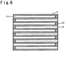
- the honeycomb filter 1 is put in a drying machine and heated in the air from room temperature to 150°C at a temperature-raising rate of 300°C/h, held at 150°C for one hour and then left to stand for cooling. After the honeycomb filter 1 was adequately cooled, it was taken out from the drying machine. In the obtained honeycomb filter 1, the composition 10 alone is packed in a checkered pattern on one end surface 8. The outer appearance of the end surface 8 of the honeycomb filter after the masking material is removed is shown in Fig. 5.
- the composition 10 is packed in the same manner so that the composition 10 is packed in one end surface of the through-hole 11 and the other end surface is left open. That is, the composition 10 is packed in the checkered pattern on both end surfaces of the filter so that the composition 10 is packed in one end surface of each through-hole 11 and the other end surface is left open to obtain a honeycomb filter 1.
- the longitudinal section of the honeycomb filter 1 is shown in Fig. 6.
- the honeycomb filter 1 having the composition 10 alone packed therein was put in a sintering furnace capable of controlling the atmosphere and heated so that the metal silicon particles contained in the composition 10 were nitrided and the composition 10 functioned as a sealing material.
- the temperature was raised under a nitrogen pressure of 1.1 MPa from room temperature to 500°C with a temperature-raising rate of 200°C/h, held at 500°C for 2 hours, and then raised from 500°C to 1,400°C at a temperature-raising rate of 300°C/h, and held at 1,400°C for 4 hours for nitriding.
- the nitriding ratio was 97% as calculated from the change in mass.
- an exhaust gas from a diesel engine was introduced to the honeycomb filter 1, and whether particulates were included in the exhaust gas after passed through the filter is confirmed by means of a smoke tester manufactured by Bacharach Company.
- the particulate concentration in the exhaust gas after passed through the filter was confirmed to be at level 1 among levels 1 to 10, the level 1 being lowest, and substantially no leakage through the sealing material was confirmed.
- Example 1 For comparison, to the same silicon nitride honeycomb filter as in Example 1, a film for masking, on which holes were preliminarily provided in a checkered pattern so that the sealing material passes therethrough, was attached, and the same sealing material as in Example 1 was packed by an injection method.
- a part of the film for masking broke in the process of injection, and it was observed that the sealing material was packed in a part other than the part to be sealed. Further, incomplete packing and variation in the amount of the packed sealing material were visually observed.
- a sealing method can be provided, with which secure air-tightness at the filter end surface can be obtained, with which durability can be obtained, and which can be carried out easily with a high productivity. Further, with this method, metal silicon particles are used as a sealing material to seal the filter by a nitriding reaction, whereby substantially no firing shrinkage occurs, no crack or the like forms on the wall of the filter at the end surface, and the filter is less damaged.
Landscapes
- Chemical & Material Sciences (AREA)
- Engineering & Computer Science (AREA)
- Ceramic Engineering (AREA)
- Chemical Kinetics & Catalysis (AREA)
- Inorganic Chemistry (AREA)
- Structural Engineering (AREA)
- Manufacturing & Machinery (AREA)
- Mechanical Engineering (AREA)
- Materials Engineering (AREA)
- Organic Chemistry (AREA)
- Geometry (AREA)
- Physics & Mathematics (AREA)
- Life Sciences & Earth Sciences (AREA)
- Geology (AREA)
- Combustion & Propulsion (AREA)
- General Engineering & Computer Science (AREA)
- Filtering Materials (AREA)
Applications Claiming Priority (2)
| Application Number | Priority Date | Filing Date | Title |
|---|---|---|---|
| JP2001141931 | 2001-05-11 | ||
| JP2001141931 | 2001-05-11 |
Publications (2)
| Publication Number | Publication Date |
|---|---|
| EP1256368A2 true EP1256368A2 (de) | 2002-11-13 |
| EP1256368A3 EP1256368A3 (de) | 2002-12-18 |
Family
ID=18988309
Family Applications (1)
| Application Number | Title | Priority Date | Filing Date |
|---|---|---|---|
| EP02009377A Withdrawn EP1256368A3 (de) | 2001-05-11 | 2002-05-06 | Verfahren zur Abdichtung eines Siliziumnitridfilters und Zusammensetzung zur Abdichtung |
Country Status (5)
| Country | Link |
|---|---|
| US (1) | US7118706B2 (de) |
| EP (1) | EP1256368A3 (de) |
| CN (1) | CN1229164C (de) |
| CZ (1) | CZ20021640A3 (de) |
| RU (1) | RU2002112421A (de) |
Families Citing this family (6)
| Publication number | Priority date | Publication date | Assignee | Title |
|---|---|---|---|---|
| EP1256368A3 (de) | 2001-05-11 | 2002-12-18 | Asahi Glass Company Ltd. | Verfahren zur Abdichtung eines Siliziumnitridfilters und Zusammensetzung zur Abdichtung |
| US6884055B2 (en) * | 2002-05-29 | 2005-04-26 | The Boeing Company | Potting compound injection apparatus and method of injecting potting compound into panel cells |
| EP1502904A1 (de) * | 2003-07-31 | 2005-02-02 | Asahi Glass Company, Limited | Methode zur Herstellung eines Wabenfilters aus Siliziumnitrid |
| JP2006160533A (ja) * | 2004-12-02 | 2006-06-22 | Asahi Glass Co Ltd | 窒化ケイ素質ハニカムフィルタの製造法 |
| WO2007037222A1 (ja) * | 2005-09-28 | 2007-04-05 | Ibiden Co., Ltd. | ハニカムフィルタ |
| WO2007096986A1 (ja) * | 2006-02-24 | 2007-08-30 | Ibiden Co., Ltd. | 端面加熱装置、ハニカム集合体の端面乾燥方法、及び、ハニカム構造体の製造方法 |
Family Cites Families (17)
| Publication number | Priority date | Publication date | Assignee | Title |
|---|---|---|---|---|
| US3819786A (en) * | 1969-09-29 | 1974-06-25 | Nat Res Dev | Production of silicon nitride material components |
| JPS577215A (en) * | 1980-06-16 | 1982-01-14 | Ngk Insulators Ltd | Preparation of ceramic honeycomb filter |
| JPS5895658A (ja) * | 1981-11-30 | 1983-06-07 | 株式会社東芝 | 窒化ケイ素焼結体の製造方法 |
| JPS60171269A (ja) * | 1984-02-16 | 1985-09-04 | 黒崎窯業株式会社 | 複雑形状の窒化珪素焼結体の製法 |
| DE3514284A1 (de) * | 1985-04-19 | 1986-10-23 | Elektroschmelzwerk Kempten GmbH, 8000 München | Verfahren zur herstellung von formkoerpern aus reaktionsgebundenem siliciumnitrid durch nitridierung unter hohem stickstoffgasdruck |
| JP3083884B2 (ja) | 1991-09-27 | 2000-09-04 | イビデン株式会社 | ハニカムフィルタの封止材料 |
| DE69510979T2 (de) * | 1994-03-30 | 1999-12-02 | Honda Giken Kogyo K.K., Tokio/Tokyo | Kompositpulver aus Siliciumnitrid und Siliciumcarbid |
| JP3461610B2 (ja) * | 1995-03-08 | 2003-10-27 | 電気化学工業株式会社 | 封止材料及びこれを用いたセラミックハニカム構造体並びにその製造方法 |
| JP3012167B2 (ja) * | 1995-04-12 | 2000-02-21 | 日本碍子株式会社 | 排ガス浄化フィルタおよびそれを用いた排ガス浄化装置 |
| US5846276A (en) * | 1995-07-05 | 1998-12-08 | Matsushita Electric Industrial Co., Ltd. | Exhaust gas filter |
| US5914187A (en) * | 1996-01-12 | 1999-06-22 | Ibiden Co., Ltd. | Ceramic structural body |
| ES2180668T3 (es) * | 1996-03-23 | 2003-02-16 | Heimbach Gmbh Thomas Josef | Cuerpo moldeado poroso apto para flujo pasante a su traves y procedimiento para su fabricacion. |
| JP3067740B2 (ja) * | 1997-08-20 | 2000-07-24 | 住友電気工業株式会社 | セラミックス製フィルターモジュール |
| JP3373502B2 (ja) * | 1999-12-24 | 2003-02-04 | 旭硝子株式会社 | 窒化ケイ素フィルタおよびその製造法 |
| JP2002173381A (ja) * | 2000-12-01 | 2002-06-21 | Denso Corp | セラミックハニカム成形体の目封止方法 |
| PL366538A1 (pl) * | 2001-04-23 | 2005-02-07 | Dow Global Technologies Inc. | Sposób wytwarzania monolitycznego filtra z przepływem ściennym |
| EP1256368A3 (de) | 2001-05-11 | 2002-12-18 | Asahi Glass Company Ltd. | Verfahren zur Abdichtung eines Siliziumnitridfilters und Zusammensetzung zur Abdichtung |
-
2002
- 2002-05-06 EP EP02009377A patent/EP1256368A3/de not_active Withdrawn
- 2002-05-08 RU RU2002112421/06A patent/RU2002112421A/ru not_active Application Discontinuation
- 2002-05-08 US US10/140,162 patent/US7118706B2/en not_active Expired - Fee Related
- 2002-05-10 CN CNB021193169A patent/CN1229164C/zh not_active Expired - Fee Related
- 2002-05-13 CZ CZ20021640A patent/CZ20021640A3/cs unknown
Also Published As
| Publication number | Publication date |
|---|---|
| CZ20021640A3 (cs) | 2003-11-12 |
| US20020185787A1 (en) | 2002-12-12 |
| RU2002112421A (ru) | 2003-11-27 |
| CN1390624A (zh) | 2003-01-15 |
| US7118706B2 (en) | 2006-10-10 |
| CN1229164C (zh) | 2005-11-30 |
| EP1256368A3 (de) | 2002-12-18 |
Similar Documents
| Publication | Publication Date | Title |
|---|---|---|
| EP1728775B1 (de) | Siliziumnitrid Filter und Verfahren zu dessen Herstellung | |
| US7951324B2 (en) | Method for manufacturing honeycomb structure | |
| EP1493724B1 (de) | Poröses material und herstellungsverfahren dafür | |
| EP1780187B1 (de) | Wabenstruktur | |
| EP1245262B1 (de) | Verfahren zur Herstellung eines Abgasreinigungsfilters | |
| JP2005534474A (ja) | ムライト・チタン酸アルミニウム製ディーゼル微粒子フィルタ | |
| CN1795037B (zh) | 密封的蜂窝结构体及其制造方法 | |
| EP1832565A1 (de) | Vorrichtung zur siliziumcarbidbrennung und verfahren zur herstellung poröser sililzumcarbidkörper | |
| EP1790407A1 (de) | Poröses wabenfilter | |
| KR20070008701A (ko) | 다공성 세라믹체 강도 증가 방법 및 그로부터 만들어지는세라믹체 | |
| JP2002154876A (ja) | ハニカム構造体及びその製造方法 | |
| CN108686440A (zh) | 蜂窝过滤器 | |
| US7118706B2 (en) | Method of sealing a silicon nitride filter | |
| EP1759754B1 (de) | Verfahren zur herstellung eines filters für abgasreinigungssystem | |
| EP2105181B1 (de) | Wabenstrukturkörper | |
| US6838026B2 (en) | Method for producing a silicon nitride filter | |
| EP1995226A1 (de) | Poröser gegenstand auf basis von siliciumcarbid und herstellungsverfahren dafür | |
| JP5341597B2 (ja) | 窒化ケイ素フィルターの製造方法及び窒化ケイ素フィルター | |
| JP2003047812A (ja) | 窒化ケイ素質フィルタの封止方法および封止用組成物 | |
| CN109415274B (zh) | 蜂窝结构体和蜂窝结构体的制造方法 | |
| EP2329874B1 (de) | Wabenfilter und Abgasreinigungsvorrichtung | |
| CN112437763A (zh) | 具有高强度表皮的陶瓷蜂窝体及其制造方法 | |
| CN112588042A (zh) | 一种烟气除尘脱硝用陶瓷过滤元件及其制备方法和应用 | |
| JP2005046764A (ja) | 窒化ケイ素質ハニカムフィルタ用封止材、それを用いた窒化ケイ素質ハニカムフィルタの封止法 | |
| CA2619598C (en) | Improved method for debindering ceramic honeycombs |
Legal Events
| Date | Code | Title | Description |
|---|---|---|---|
| PUAI | Public reference made under article 153(3) epc to a published international application that has entered the european phase |
Free format text: ORIGINAL CODE: 0009012 |
|
| PUAL | Search report despatched |
Free format text: ORIGINAL CODE: 0009013 |
|
| AK | Designated contracting states |
Kind code of ref document: A2 Designated state(s): AT BE CH CY DE DK ES FI FR GB GR IE IT LI LU MC NL PT SE TR |
|
| AX | Request for extension of the european patent |
Free format text: AL;LT;LV;MK;RO;SI |
|
| AK | Designated contracting states |
Kind code of ref document: A3 Designated state(s): AT BE CH CY DE DK ES FI FR GB GR IE IT LI LU MC NL PT SE TR |
|
| AX | Request for extension of the european patent |
Free format text: AL;LT;LV;MK;RO;SI |
|
| RIC1 | Information provided on ipc code assigned before grant |
Free format text: 7B 01D 46/24 A, 7B 01D 39/20 B, 7C 04B 35/591 B, 7F 01N 3/022 B |
|
| 17P | Request for examination filed |
Effective date: 20030327 |
|
| AKX | Designation fees paid |
Designated state(s): AT BE CH CY DE DK ES FI FR GB GR IE IT LI LU MC NL PT SE TR |
|
| 17Q | First examination report despatched |
Effective date: 20071016 |
|
| STAA | Information on the status of an ep patent application or granted ep patent |
Free format text: STATUS: THE APPLICATION IS DEEMED TO BE WITHDRAWN |
|
| 18D | Application deemed to be withdrawn |
Effective date: 20091201 |