EP1249590B1 - Motorgenerator - Google Patents
Motorgenerator Download PDFInfo
- Publication number
- EP1249590B1 EP1249590B1 EP02008407A EP02008407A EP1249590B1 EP 1249590 B1 EP1249590 B1 EP 1249590B1 EP 02008407 A EP02008407 A EP 02008407A EP 02008407 A EP02008407 A EP 02008407A EP 1249590 B1 EP1249590 B1 EP 1249590B1
- Authority
- EP
- European Patent Office
- Prior art keywords
- engine
- power generating
- generating body
- adapter
- generator
- Prior art date
- Legal status (The legal status is an assumption and is not a legal conclusion. Google has not performed a legal analysis and makes no representation as to the accuracy of the status listed.)
- Expired - Fee Related
Links
Images


Classifications
-
- F—MECHANICAL ENGINEERING; LIGHTING; HEATING; WEAPONS; BLASTING
- F02—COMBUSTION ENGINES; HOT-GAS OR COMBUSTION-PRODUCT ENGINE PLANTS
- F02B—INTERNAL-COMBUSTION PISTON ENGINES; COMBUSTION ENGINES IN GENERAL
- F02B75/00—Other engines
- F02B75/16—Engines characterised by number of cylinders, e.g. single-cylinder engines
-
- F—MECHANICAL ENGINEERING; LIGHTING; HEATING; WEAPONS; BLASTING
- F02—COMBUSTION ENGINES; HOT-GAS OR COMBUSTION-PRODUCT ENGINE PLANTS
- F02B—INTERNAL-COMBUSTION PISTON ENGINES; COMBUSTION ENGINES IN GENERAL
- F02B63/00—Adaptations of engines for driving pumps, hand-held tools or electric generators; Portable combinations of engines with engine-driven devices
- F02B63/04—Adaptations of engines for driving pumps, hand-held tools or electric generators; Portable combinations of engines with engine-driven devices for electric generators
- F02B63/044—Adaptations of engines for driving pumps, hand-held tools or electric generators; Portable combinations of engines with engine-driven devices for electric generators the engine-generator unit being placed on a frame or in an housing
- F02B2063/045—Frames for generator-engine sets
-
- F—MECHANICAL ENGINEERING; LIGHTING; HEATING; WEAPONS; BLASTING
- F02—COMBUSTION ENGINES; HOT-GAS OR COMBUSTION-PRODUCT ENGINE PLANTS
- F02B—INTERNAL-COMBUSTION PISTON ENGINES; COMBUSTION ENGINES IN GENERAL
- F02B63/00—Adaptations of engines for driving pumps, hand-held tools or electric generators; Portable combinations of engines with engine-driven devices
- F02B63/04—Adaptations of engines for driving pumps, hand-held tools or electric generators; Portable combinations of engines with engine-driven devices for electric generators
- F02B63/044—Adaptations of engines for driving pumps, hand-held tools or electric generators; Portable combinations of engines with engine-driven devices for electric generators the engine-generator unit being placed on a frame or in an housing
- F02B63/048—Portable engine-generator combinations
-
- F—MECHANICAL ENGINEERING; LIGHTING; HEATING; WEAPONS; BLASTING
- F05—INDEXING SCHEMES RELATING TO ENGINES OR PUMPS IN VARIOUS SUBCLASSES OF CLASSES F01-F04
- F05C—INDEXING SCHEME RELATING TO MATERIALS, MATERIAL PROPERTIES OR MATERIAL CHARACTERISTICS FOR MACHINES, ENGINES OR PUMPS OTHER THAN NON-POSITIVE-DISPLACEMENT MACHINES OR ENGINES
- F05C2201/00—Metals
- F05C2201/02—Light metals
- F05C2201/021—Aluminium
Definitions
- the present invention relates to an engine generator including an engine and a power generating body driven by the engine. More particularly, the present invention relates to an engine generator which allows a power generating body based on one control system to be replaced with another power generating body based on another control system.
- a rotor provided with a magnet having at least 20 poles is rotated at high speed, so that it is capable of generating higher electric power than that generated by the conventional engine generator of the AVR type.
- the electronic parts of the control unit are large in size, and the control unit per se is also large.
- the structures of the engine generators based on both the control systems are greatly different from each other. Accordingly, even in a design of only the control units of the engine generators, it is difficult to design them so as to satisfy common specifications. For this reason, it is a general practice of the engine generator design to employ either of the control systems for its control system. Accordingly, also in production and sales stages, a manufacturer is obliged to grasp the demands of both the control systems, and then to manufacture and purchase the related merchandize. Excessive stock or shortage of merchandize in stock is likely to occur, and it is difficult to secure an optimum stock.
- the engine generator may be categorized into two types depending on an interior structure thereof.
- a first type of the engine generator is structured such that, as disclose in Japanese Patent Unexamined Publication No. Hei. 8-223854 , one end part of a crank shaft of the engine is used as an output shaft thereof.
- the power generating body is provided on the output shaft, whereas a recoil starter is provided on the other end.
- a recoil starter is provided on the other end.
- component parts are disposed on both sides of the engine.
- the part layout is easy in this type, so that a structure of the device is relatively simple.
- a second type of the engine generator is structured such that one end part of the crank shaft is used as an output shaft thereof, and the power generating body and the recoil starter are mounted on the output shaft.
- This type of the engine generator is more complex in structure than the first type of the engine generator, but the whole device is made compact advantageously.
- the number of mounting parts is large. This necessitates use of a long dedicated crank shaft. This hinders the use of the general purpose engine for the engine generator. Even when the dedicated parts are used, the flywheel and the cooling fan are mounted on the tapered part of the crank shaft, and the power generating body is mounted at a position subsequent to them. For this reason, in the power generating body mounting part, it is impossible to secure a sufficient tapered shaft diameter.
- the present invention provides an engine generator in accordance with independent claim 1. Preferred embodiments of the invention are reflected in the dependent claims.
- an engine generator comprising:
- the adapter is connected to said flywheel, and said power generating body is detachably attached to said adapter to allow replacement of said power generating body, and the recoil device is disposed outside said fan cover and engages with a recoil ring mounted on said adapter.
- Fig. 1 is a front view showing an engine generator, which is an embodiment of the invention.
- Fig. 2 is a plan view showing the Fig. 1 engine generator, and
- Fig. 3 is a rear view of the same.
- An engine generator 1 of the embodiment is structured such that a generator unit 5 in which an engine 3 serving as a drive source and a power generating body 4 are integrally assembled onto a support frame 2 formed by bending a pipe into a rectangular frame, is elastically supported by a plurality of supporting pieces 6.
- the engine generator 1 employs an inverter type control system for the control system.
- An inverter unit 11 for controlling a generated voltage is mounted on the side (rear side in Fig. 3 ) of the inverter unit 11 (see Fig. 1 ).
- a control panel 7 is provided on the front side of the engine generator.
- the control panel 7 contains various switches, such as an engine switch and an auto throttle switch, and output terminals, such as an AC power source terminal and a DC power source terminal.
- a recoil knob 8a for driving a recoil starter 8 is provided on the lower side of the control panel 7. When the recoil knob is pulled, the engine 3 is turned on.
- a fuel tank 9 for storing fuel to be supplied to the engine 3 is provided above the generator unit 5.
- a fuel supply port is provided at the center part on the upper surface of the fuel tank 9.
- a fuel cap 10 is attached to the fuel supply port such that it may open and close the fuel supply port.
- Fig. 4 is a front view showing a generator unit 5 used in the Fig. 1 engine generator;
- Fig. 5 is a plan view of the same;
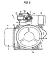
- Fig. 6 is a right side view showing the generator unit of Fig. 5 (as seen in the direction of an arrow X);
- Fig. 7 is a left side view showing the generator unit of Fig. 4 (as seen in the direction of an arrow Y);
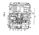
- Fig. 8 is a cross sectional view taken on line Z-Z in Fig. 5 .
- the inverter unit 11 is mounted on the side of the generator unit 5 as shown in Figs. 4 and 6 .
- the inverter unit 11 converts an electric power output from the power generating body 4 into an AC electric power at a predetermined frequency by controlling the output power.
- the inverter unit 11 is structured such that electronic circuit boards are mounted within a case 71 made of aluminum, and is directly fixed to a fan cover 53 made of aluminum.
- the engine 3 is an air-cooled single cylinder OHV gasoline engine.
- the engine 3 includes a crank case 31 and a cylinder 32 provided above the crank case 31.
- a head covert 33 is mounted on the cylinder 32.
- An ignition coil 37 integral with a plug cap is attached to the cylinder 32.
- a carburetor 12 is provided on the intake side of the engine 3. Air is introduced through an air cleaner 36 into the carburetor 12 where air is mixed with gasoline to form an air-fuel mixture, and the air-fuel mixture is fed to the engine 3.
- a muffler 14 is coupled to the exhaust side of the engine through an exhaust pipe 13. An exhaust gas from the engine 3 passes through the muffler 14 and is exhausted outside through an exhaust port 15, which is provided on the left side of the apparatus in Fig. 4 .
- a throttle valve 16 is provided on the carburetor 12, as shown in Fig. 6 .
- the throttle valve 16 is opened and closed by a carburetor throttle lever 17, which is provided on the upper part of the carburetor 12.
- One end of a governor rod 18a is connected to the carburetor throttle lever 17.
- the engine speed of the engine 3 is controlled to be constant while being not affected by a load variation, by a mechanical governor.
- a governor shaft 19 is rotatably mounted on the crank case 31.
- the base end of a governor lever 20 is connected to the governor shaft.
- a tension coil spring 22 coupled with a speed control lever 21 is hooked on the governor lever 20.
- the governor lever 20 is urged in the clockwise direction in Fig. 5 by the tension coil spring 22.
- one end of a governor rod 18b is coupled to the tip end of the governor lever 20.
- the other end of the governor rod 18b is coupled to a control lever 23.
- the control lever 23 is rotatably supported on a plate 25, which is mounted on the upper part of the generator unit 5.
- the other end of the governor rod 18a whose one end is coupled to the carburetor throttle lever 17 is coupled to the control lever 23. Accordingly, when the governor lever 20 is turned about the governor shaft 19, the governor rod 18b, the control lever 23 and the governor rod 18a are moved in an interlocking manner, and the carburetor throttle lever 17 is operated.
- the governor shaft 19 is engaged with a governor sleeve being axially slidably mounted on the shaft, which is driven to rotate by the crank shaft 34 of the engine 3.
- a rotary body is fastened to the shaft.
- a plurality of governor arms are rotatably mounted on the end face of the rotary body at positions arrayed radially from the center of the end face.
- Governor weights are integrally provided on those governor arms, whereby a mechanical governor mechanism is formed.
- crank shaft 34 assembled into a crank case 31 is disposed extending in the horizontal directions in Fig. 8 .
- one end of the crank shaft 34 functions as an output shaft of the engine 3.
- the flywheel 51, cooling fan 52, recoil starter (recoil device) 8 and power generating body 4 are disposed in this order on the output shaft.
- the flywheel 51 and the cooling fan 52 are mounted at positions subsequent to the engine 3.
- the recoil starter 8 and the power generating body 4 are disposed at positions located beyond the adapter 55 fastened to the flywheel 51.
- crank shaft 34 of the engine 3 is supported by a bearing 35 mounted on the crank case 31.
- the other end of the crank shaft 34 is also supported by a bearing, not shown, located on the opposite side to that, and is rotatable with respect to the crank case 31.
- One end 34a of the crank shaft is protruded out of the crank case 31, and the flywheel 51 for stabilizing the engine output of the engine 3, such as engine speed and torque, is mounted on the one end.
- the flywheel 51 includes a boss part 51a fastened to the crank shaft 34 with the aid of a key, and a disc part 51b radially expanding from the boss part 51a.
- a cooling fan 52 is mounted on the disc part 51b.
- the cooling fan 52 includes a disc part 52a, and a number of fan blades 52b integrally formed on the surface of the disc part 52a.
- the cooling fan 52 is covered with a fan cover 53 to be fastened to the engine 3.
- the fan cover 53 is made of aluminum, and includes a number of slits 54 serving as cooling air intake ports, which are formed on the side surface.
- the fan cover 53 functions as a duct for guiding air. As shown in Fig. 8 , with rotation of the cooling fan 52, air is introduced into the fan cover 53 through the slits 54, and fed and guided as cooling air to the engine 3.
- a recoil starter 8 is disposed at a position subsequent to the flywheel 51.
- a recoil ring 56 is mounted on a boss part 51a of the flywheel 51, through the adapter 55.
- a recoil holder 57 integral with the disc part 57a and the cylindrical part 57b, is disposed at a position subsequent to it.
- a recoil pulley 59 to be wound thereon with a recoil rope 58 is rotatably mounted on the outside of the cylindrical part 57b.
- An engaging pawl (not shown) is provided on the recoil pulley 59.
- the recoil knob 8a is pulled and the recoil pulley 59 is rotated by the recoil rope 58, the engaging pawl is brought into engagement with the recoil ring 56.
- the crank shaft 34 coupled therewith through the adapter 55, is rotated to start the operation of the engine 3.
- a rewind spring is provided on the recoil holder 57.
- a recoil rope 58 is rewound onto the recoil pulley 59 by a spring force thereof.
- a power generating body 4 is disposed subsequent to the recoil starter 8.
- the engine 3 the flywheel 51, the cooling fan 52 and the recoil starter 8 make up a engine unit (engine unit part) 110 for driving the power generating body.
- the power generating body 4 may be attached thereto, with the help of the adapter 55.
- the power generating body 4 which employs the inverter control system for the control system is attached to the engine generator. If required, a power generating body of the AVR type to be described later may be used instead.
- the power generating body 4 is of the inner rotor type, and contains an inner rotor 41 and a stator 42.
- the inner rotor 41 is formed with a rotor shaft 43 and a rotor disc 45.
- the rotor shaft 43 is fastened to the tip of the boss part 55a of the adapter 55 by a through bolt 60.
- a tapered part 55b is formed in the boss part 55a.
- the tapered part 55b is fit into a tapered hole 43a formed in the rotor shaft 43.
- the flywheel 51 is directly fastened on the crank shaft 34, as described above.
- An adapter 55 is mounted on the flywheel 51, and an engine 3 is fastened to the adapter 55.
- the rotor shaft 43 of the power generating body 4 is coupled to the crank shaft 34 with the aid of the adapter 55.
- the flywheel 51 and the power generating body 4 are coupled together by the adapter 55. Therefore, even if the recoil starter 8, the power generating body 4 and the like are disposed on the output shaft side, there is no need of using a long dedicated crank shaft.
- the parts may be laid out as shown in Fig. 8 without any alteration of an engine side, e.g., a crank shaft. Accordingly, a general purpose engine may be used without using any dedicated part, and the product cost may be reduced. Since the rotor shaft 43 is fastened by using the adapter 55, a sufficient large diameter of the tapered part is secured. Those may be coupled together at sufficient strength.
- the other end of the rotor shaft 43 is rotatably supported by a bearing 61 mounted on the rear cover 44 of the power generating body.
- the stator 42 is disposed outside the inner rotor 41. In this instance, the stator 42 is held between the fan cover 53 and the rear cover 44.
- a plurality of magnets are mounted on the outer peripheral surface of the inner rotor 41 in the circumferential direction.
- a core 62 which is formed of a lamination of a number of copper plates, is provided on the stator 42.
- the core 62 is wound by a coil 63. With rotation of the crank shaft 34, the magnets of the inner rotor 41 rotate inside the coil 63, whereby a electromotive force is generated in the coil 63, leading to power generation.
- a rear cover 44 is formed with a disc part 44a having a ventilation hole 64 formed therein and a cylindrical part 44b integral with the disc part.
- the rear cover 44 is fastened at the cylindrical part 44b to the fan cover 53.
- the stator 42 is held between it and the fan cover 53.
- air is introduced from the ventilation hole 64 into the rear cover 44, and flows to the engine 3 while cools the stator 42 and the like.
- Air also flows into the generator unit 5, through slits 54 formed on the side part of the fan cover 53.
- the air current joins the cooling air after it is introduced through the ventilation hole 64 and cools the stator 42 and the like, and guided by the fan cover 53 and blows against the periphery of the engine 3.
- one cooling fan 52 causes two cooling air currents, one flowing through the slits 54 and the other flowing through the ventilation hole 64, whereby the power generating body 4 and the engine 3 are both cooled.
- the cooling air made to blow against the engine 3 flows to the rear side of the engine 3 and cools the muffler 14.
- the cooling fan 52 is disposed between the engine 3 and the power generating body 4, as shown in Fig. 8 . With this structure, the power generating body 4 is little affected by engine exhaust heat. In this respect, the cooling effect of the power generating body 4 is facilitated.
- the power generating body 4 disposed subsequent to the adapter 55 is replaceable, viz., the power generating body based on one control system may be replaced with another power generating body based on another control system, which is different from the former.
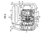
- Figs. 9 and 10 are explanatory diagrams useful in explaining engine generators each arranged so as to allow the replacement of the power generating body.
- Fig. 9 shows an engine generator 1inv attached with an inverter type power generating body.
- Fig. 10 shows an engine generator 1avr attached with an AVR type power generating body.
- the structure of the Fig. 9 engine generator, except the power generating body, is substantially the same as of the Fig. 10 engine generator.
- like reference numerals are used for designating like and equivalent portions.
- a power generating body 4 based on the inverter control system is attached to the engine unit 110.
- a length of the engine generator linv as viewed in the crank shaft 34 direction is slightly longer than that of the engine generator 1 already stated.
- the inverter unit 11 is disposed at the left side part of the generator unit 5 in the drawing. Other structure than this is substantially the same as of the already stated one.
- an AVR type power generating body 111 is attached to the engine unit 110.
- the power generating body 111 like the power generating body 4, is also of the inner rotor type, and contains an inner rotor 112 and a stator 113.
- the inner rotor 112 is formed with a rotor shaft 114 and a rotor disc 115.
- the rotor shaft 114 is fastened to the tip of the boss part 55a of the adapter 55 by a through bolt 116.
- a tapered hole 114a is formed also in the rotor shaft 114, and is to be fit to the tapered part 55b.
- the other end of the rotor shaft 114 is rotatably supported by a bearing 118 mounted on a generator rear cover 117.
- the stator 113 is disposed outside the inner rotor 112.
- the stator 113 is held between the fan cover 53 and the generator rear cover 117.
- Magnets (not shown) are mounted on the outer peripheral surface of the inner rotor 112 in the circumferential direction.
- a coil 120 is wound on a coil 119.
- the outside diameter of the stator 113 is selected to be equal to that of the stator 42.
- the entire length of the power generating body 111 is substantially equal to the corresponding one in the case where the power generating body 4 and the inverter unit 11 are both used.
- the power generating body 4 is attached to the engine unit 110. Since the stator 113 and the stator 42 are equal in outside diameter as described above, either of those stators may be attached to the fan cover 53. And, the stator 42 is mounted onto between the fan cover 53 and the rear cover 44, and the power generating body 4 is fastened to the adapter 55. Thereafter, the inverter unit 11 is attached to the structure, an engine generator 1inv is completed in structure, and here the replacing work of the power generating body ends.
- the generator unit 5 is divided into two sections, the engine unit 110 and the power generating body 4 (111), and those sections are interconnected by the adapter 55.
- the engine unit 110 contains the engine 3, and the flywheel 51 and the cooling fan 52, and further the recoil starter 8 by use of the adapter 55.
- the rotor shaft 43 (115) of the power generating body 4 (111) is fastened to the adapter 55, and the stator 42 (113) equalized in outside diameter is fastened to the fan cover 53 by use of the rear cover 44 (117).
- the power generating body 4 may be replaced with the power generating body 111 (4) by a simple replacing work, e.g., simple work of removing bolts.
- the Fig. 9 engine generator 1inv may be replaced with the Fig. 10 engine generator lavr.
- the engine generators of the AVR type are manufactured as the standard specification.
- the engine generators of the inverter type are stocked in shops and the like.
- the AVR type power generating body is changed to the inverter type one, viz., the product specifications are changed according to the customer's desire. Therefore, there is no need for the alternative manufacturing and purchasing, and the invention succeeds in eliminating the excessive stock or shortage of merchandize in stock.
- an adapter to which the power generating body is detachably attached for its replacement is provided between the drive unit part and the power generating body.
- This feature enables one to replace the power generating body with another power generating body by a simple replacing work. Accordingly, one can replace the power generating body with another power generating body, and change the product specifications to other ones.
- a power generating body based on a control system which is different from a control system of an existing power generating body is allowed to be attached to the drive unit part with the aid of the adapter. Therefore, in a specific example, one can replace a power generating body of the AVR type with another power generating body of the inverter type. Accordingly, there is no need for the alternative manufacturing and purchasing, and the invention succeeds in eliminating the excessive stock or shortage of merchandize in stock.
- a flywheel, a cooling fan, a recoil starter, and a power generating body are disposed in this order from the engine.
- the power generating body and the engine are both cooled by use of one cooling fan.
Landscapes
- Engineering & Computer Science (AREA)
- Chemical & Material Sciences (AREA)
- Combustion & Propulsion (AREA)
- Mechanical Engineering (AREA)
- General Engineering & Computer Science (AREA)
- Connection Of Motors, Electrical Generators, Mechanical Devices, And The Like (AREA)
Claims (4)
- Motorgenerator, welcher enthält:einen Motor;einen durch den Motor angetriebenen Energieerzeugungskörper;einen Adapter, welcher zwischen dem Motor und dem Energieerzeugungskörper angeordnet ist;ein Schwungrad, welches an einem Ende von einer Welle von dem Motor angeordnet ist, wobei ein Kühllüfter auf dem Schwungrad befestigt ist;eine Lüfterabdeckung, welche an dem Motor befestigt ist, um das Schwungrad und den Kühllüfter darin einzufassen; undeine Aufwickelvorrichtung, um den Motor zu starten;wobei der Adapter mit dem Schwungrad verbunden ist;wobei der Energieerzeugungskörper an dem Adapter entnehmbar angebracht ist, um einen Austausch des Energieerzeugungskörpers zu ermöglichen; undwobei die Aufwickelvorrichtung außerhalb der Lüfterabdeckung angeordnet ist und mit einem Aufwickelring, welcher an dem Adapter befestigt ist, einrückt.
- Motorgenerator nach Anspruch 1, bei welchem der Aufwickelring an dem Adapter verschraubt ist.
- Motorgenerator nach Anspruch 1, bei welchem der Adapter einen gemeinsamen Befestigungsabschnitt hat, an welchem eine Mehrzahl von Energieerzeugungskörpern einzeln befestigbar sind, wobei die Mehrzahl von Energieerzeugungskörpern Steuersysteme haben, welche zueinander unterschiedlich sind.
- Motorgenerator nach Anspruch 3, bei welchem die Steuersysteme von dem Energieerzeugungskörper einen automatischen Spannungsregeltyp und einen Invertertyp enthalten.
Applications Claiming Priority (4)
| Application Number | Priority Date | Filing Date | Title |
|---|---|---|---|
| JP2001115625A JP3983006B2 (ja) | 2001-04-13 | 2001-04-13 | エンジン発電機 |
| JP2001115621 | 2001-04-13 | ||
| JP2001115625 | 2001-04-13 | ||
| JP2001115621A JP3905324B2 (ja) | 2001-04-13 | 2001-04-13 | エンジン発電機 |
Publications (3)
| Publication Number | Publication Date |
|---|---|
| EP1249590A2 EP1249590A2 (de) | 2002-10-16 |
| EP1249590A3 EP1249590A3 (de) | 2003-07-02 |
| EP1249590B1 true EP1249590B1 (de) | 2008-09-03 |
Family
ID=26613579
Family Applications (1)
| Application Number | Title | Priority Date | Filing Date |
|---|---|---|---|
| EP02008407A Expired - Fee Related EP1249590B1 (de) | 2001-04-13 | 2002-04-12 | Motorgenerator |
Country Status (3)
| Country | Link |
|---|---|
| US (1) | US6825573B2 (de) |
| EP (1) | EP1249590B1 (de) |
| DE (1) | DE60228644D1 (de) |
Families Citing this family (16)
| Publication number | Priority date | Publication date | Assignee | Title |
|---|---|---|---|---|
| JP2004346873A (ja) * | 2003-05-23 | 2004-12-09 | Honda Motor Co Ltd | エンジン駆動作業機 |
| US7264069B2 (en) * | 2004-10-11 | 2007-09-04 | Briggs And Stratton Corporation | Vehicle or lawn and garden maintenance equipment having a generator, and power takeoff assembly for a vehicle or lawn and garden maintenance equipment |
| JP2006291927A (ja) * | 2005-04-14 | 2006-10-26 | Yamaha Motor Co Ltd | 船外型発電機 |
| US7239032B1 (en) * | 2005-11-18 | 2007-07-03 | Polaris Industries Inc. | Starter-generator |
| US9187083B2 (en) | 2009-09-16 | 2015-11-17 | Polaris Industries Inc. | System and method for charging an on-board battery of an electric vehicle |
| EP2308708B1 (de) | 2009-09-16 | 2016-08-17 | swissauto powersport llc | Elektrofahrzeug mit Reichweitenverlängerung |
| CA3138437A1 (en) | 2016-06-14 | 2017-12-21 | Polaris Industries Inc. | Hybrid utility vehicle |
| US11149630B2 (en) | 2018-05-07 | 2021-10-19 | Champion Power Equipment, Inc. | Oil drain system for a generator engine |
| US11492961B2 (en) | 2018-05-07 | 2022-11-08 | Champion Power Equipment, Inc. | Standby generator control and access panel |
| US11300034B2 (en) | 2018-05-17 | 2022-04-12 | Champion Power Equipment, Inc. | Standby generator air flow management system |
| US11177720B2 (en) | 2018-05-17 | 2021-11-16 | Champion Power Equipment, Inc. | Standby generator engine-fan-alternator configuration |
| US10907527B2 (en) | 2018-06-06 | 2021-02-02 | Champion Power Equipment, Inc. | Standby generator alternator adapter with engine cooling air intake |
| US11143099B2 (en) | 2018-06-15 | 2021-10-12 | Champion Power Equipment, Inc. | Backplate for engine-alternator coupling in standby generator |
| US11668212B2 (en) | 2018-06-20 | 2023-06-06 | Champion Power Equipment, Inc. | Double-sided oil cooler for use in a generator engine |
| US10780770B2 (en) | 2018-10-05 | 2020-09-22 | Polaris Industries Inc. | Hybrid utility vehicle |
| US11370266B2 (en) | 2019-05-16 | 2022-06-28 | Polaris Industries Inc. | Hybrid utility vehicle |
Family Cites Families (15)
| Publication number | Priority date | Publication date | Assignee | Title |
|---|---|---|---|---|
| JPS6356144A (ja) * | 1986-08-25 | 1988-03-10 | Kubota Ltd | エンジン発電機の冷却構造 |
| JPH02252970A (ja) * | 1989-03-27 | 1990-10-11 | Sawafuji Electric Co Ltd | スタータのロータおよびその製造方法 |
| DE4304630A1 (de) * | 1993-02-16 | 1994-08-18 | Prettl Rolf | Stromerzeuger für Einsatzzwecke wie Camping, Garten oder Boote |
| US5929611A (en) * | 1994-09-14 | 1999-07-27 | Coleman Powermate, Inc. | Light weight rotor and stator with multiple coil windings in thermal contact |
| JP3206633B2 (ja) | 1995-02-14 | 2001-09-10 | ヤマハ発動機株式会社 | エンジン発電機 |
| US5546901A (en) * | 1995-06-30 | 1996-08-20 | Briggs & Stratton Corporation | Engine housing for an engine-device assembly |
| US5965999A (en) * | 1997-03-20 | 1999-10-12 | Coleman Powermate, Inc. | Vertical generator assembly |
| US6084313A (en) | 1998-08-13 | 2000-07-04 | Coleman Powermate, Inc. | Generator system with vertically shafted engine |
| JP2000328956A (ja) * | 1999-05-20 | 2000-11-28 | Honda Motor Co Ltd | エンジン発電機 |
| JP3654567B2 (ja) * | 1999-05-21 | 2005-06-02 | 本田技研工業株式会社 | エンジン発電機 |
| JP3727488B2 (ja) * | 1999-05-21 | 2005-12-14 | 本田技研工業株式会社 | エンジン発電機 |
| JP3627587B2 (ja) * | 1999-09-06 | 2005-03-09 | スズキ株式会社 | 車両の推進装置 |
| JP3651575B2 (ja) * | 1999-09-06 | 2005-05-25 | スズキ株式会社 | 車両の推進装置 |
| US6624543B1 (en) * | 1999-09-23 | 2003-09-23 | Illinois Tool Works Inc. | Method and apparatus for centering a generator stator and rotor |
| JP3866480B2 (ja) * | 2000-04-14 | 2007-01-10 | 富士重工業株式会社 | エンジン発電機 |
-
2002
- 2002-04-12 US US10/121,083 patent/US6825573B2/en not_active Expired - Lifetime
- 2002-04-12 EP EP02008407A patent/EP1249590B1/de not_active Expired - Fee Related
- 2002-04-12 DE DE60228644T patent/DE60228644D1/de not_active Expired - Lifetime
Also Published As
| Publication number | Publication date |
|---|---|
| US6825573B2 (en) | 2004-11-30 |
| EP1249590A3 (de) | 2003-07-02 |
| DE60228644D1 (de) | 2008-10-16 |
| EP1249590A2 (de) | 2002-10-16 |
| US20020149203A1 (en) | 2002-10-17 |
Similar Documents
| Publication | Publication Date | Title |
|---|---|---|
| EP1249590B1 (de) | Motorgenerator | |
| US6661107B2 (en) | Engine generator | |
| US6525430B1 (en) | Portable engine generator having a fan cover with a control unit mounting portion | |
| EP1302637B1 (de) | Motorgenerator mit Lärmdämpfung | |
| EP1124046A2 (de) | Motor-Generator | |
| EP1146211B1 (de) | Motorgenerator | |
| EP1447541B1 (de) | Motorgenerator | |
| KR100537806B1 (ko) | 영구자석식 회전전동기 | |
| JP3983006B2 (ja) | エンジン発電機 | |
| JP2002309959A (ja) | エンジン発電機のエンジンコントロールスイッチ | |
| JP2001221047A (ja) | エンジン発電機 | |
| JP4097410B2 (ja) | エンジン発電機 | |
| JP3905324B2 (ja) | エンジン発電機 | |
| JP2004173343A (ja) | エンジン発電機 | |
| JP2002309956A (ja) | エンジン発電機 | |
| JP3926252B2 (ja) | エンジン発電機 | |
| JP2002309971A (ja) | エンジンのスロットルコントロール機構 | |
| KR100409257B1 (ko) | 영구 자석식 회전 전동기 및 그 구동 장치 | |
| JP2002309958A (ja) | 防音型発電機 | |
| JP2002309954A (ja) | エンジン発電機 | |
| KR100398342B1 (ko) | 차량용 교류 발전기 | |
| JP2002364358A (ja) | エンジン発電機 | |
| JP2002309920A (ja) | 汎用エンジン用マフラ | |
| JP2004169561A (ja) | エンジン発電機 | |
| JP2002180842A (ja) | 防音形エンジン発電機 |
Legal Events
| Date | Code | Title | Description |
|---|---|---|---|
| PUAI | Public reference made under article 153(3) epc to a published international application that has entered the european phase |
Free format text: ORIGINAL CODE: 0009012 |
|
| AK | Designated contracting states |
Kind code of ref document: A2 Designated state(s): AT BE CH CY DE DK ES FI FR GB GR IE IT LI LU MC NL PT SE TR |
|
| AX | Request for extension of the european patent |
Free format text: AL;LT;LV;MK;RO;SI |
|
| PUAL | Search report despatched |
Free format text: ORIGINAL CODE: 0009013 |
|
| AK | Designated contracting states |
Designated state(s): AT BE CH CY DE DK ES FI FR GB GR IE IT LI LU MC NL PT SE TR |
|
| AX | Request for extension of the european patent |
Extension state: AL LT LV MK RO SI |
|
| RIC1 | Information provided on ipc code assigned before grant |
Ipc: 7F 02B 75/16 B Ipc: 7F 02B 63/04 A |
|
| 17P | Request for examination filed |
Effective date: 20031023 |
|
| AKX | Designation fees paid |
Designated state(s): DE FR GB |
|
| 17Q | First examination report despatched |
Effective date: 20061106 |
|
| 17Q | First examination report despatched |
Effective date: 20061106 |
|
| GRAP | Despatch of communication of intention to grant a patent |
Free format text: ORIGINAL CODE: EPIDOSNIGR1 |
|
| GRAS | Grant fee paid |
Free format text: ORIGINAL CODE: EPIDOSNIGR3 |
|
| GRAA | (expected) grant |
Free format text: ORIGINAL CODE: 0009210 |
|
| AK | Designated contracting states |
Kind code of ref document: B1 Designated state(s): DE FR GB |
|
| REG | Reference to a national code |
Ref country code: GB Ref legal event code: FG4D |
|
| REF | Corresponds to: |
Ref document number: 60228644 Country of ref document: DE Date of ref document: 20081016 Kind code of ref document: P |
|
| PLBE | No opposition filed within time limit |
Free format text: ORIGINAL CODE: 0009261 |
|
| STAA | Information on the status of an ep patent application or granted ep patent |
Free format text: STATUS: NO OPPOSITION FILED WITHIN TIME LIMIT |
|
| 26N | No opposition filed |
Effective date: 20090604 |
|
| PGFP | Annual fee paid to national office [announced via postgrant information from national office to epo] |
Ref country code: GB Payment date: 20100325 Year of fee payment: 9 |
|
| PGFP | Annual fee paid to national office [announced via postgrant information from national office to epo] |
Ref country code: FR Payment date: 20100521 Year of fee payment: 9 |
|
| GBPC | Gb: european patent ceased through non-payment of renewal fee |
Effective date: 20110412 |
|
| REG | Reference to a national code |
Ref country code: FR Ref legal event code: ST Effective date: 20111230 |
|
| PG25 | Lapsed in a contracting state [announced via postgrant information from national office to epo] |
Ref country code: FR Free format text: LAPSE BECAUSE OF NON-PAYMENT OF DUE FEES Effective date: 20110502 |
|
| PG25 | Lapsed in a contracting state [announced via postgrant information from national office to epo] |
Ref country code: GB Free format text: LAPSE BECAUSE OF NON-PAYMENT OF DUE FEES Effective date: 20110412 |
|
| REG | Reference to a national code |
Ref country code: DE Ref legal event code: R082 Ref document number: 60228644 Country of ref document: DE Representative=s name: MEISSNER BOLTE PATENTANWAELTE RECHTSANWAELTE P, DE Ref country code: DE Ref legal event code: R081 Ref document number: 60228644 Country of ref document: DE Owner name: SUBARU CORPORATION, JP Free format text: FORMER OWNER: FUJI JUKOGYO K.K., TOKIO/TOKYO, JP |
|
| PGFP | Annual fee paid to national office [announced via postgrant information from national office to epo] |
Ref country code: DE Payment date: 20170404 Year of fee payment: 16 |
|
| REG | Reference to a national code |
Ref country code: DE Ref legal event code: R119 Ref document number: 60228644 Country of ref document: DE |
|
| PG25 | Lapsed in a contracting state [announced via postgrant information from national office to epo] |
Ref country code: DE Free format text: LAPSE BECAUSE OF NON-PAYMENT OF DUE FEES Effective date: 20181101 |