EP1249425A1 - Geteiltes Wälzlager für Antriebswelle einer Fahrtreppe oder eines Fahrsteiges - Google Patents
Geteiltes Wälzlager für Antriebswelle einer Fahrtreppe oder eines Fahrsteiges Download PDFInfo
- Publication number
- EP1249425A1 EP1249425A1 EP02007477A EP02007477A EP1249425A1 EP 1249425 A1 EP1249425 A1 EP 1249425A1 EP 02007477 A EP02007477 A EP 02007477A EP 02007477 A EP02007477 A EP 02007477A EP 1249425 A1 EP1249425 A1 EP 1249425A1
- Authority
- EP
- European Patent Office
- Prior art keywords
- escalator
- bearing
- axis
- moving walk
- transport chain
- Prior art date
- Legal status (The legal status is an assumption and is not a legal conclusion. Google has not performed a legal analysis and makes no representation as to the accuracy of the status listed.)
- Granted
Links
- 238000005096 rolling process Methods 0.000 claims abstract description 44
- 238000000605 extraction Methods 0.000 claims description 4
- 238000010276 construction Methods 0.000 description 4
- 230000008878 coupling Effects 0.000 description 3
- 238000010168 coupling process Methods 0.000 description 3
- 238000005859 coupling reaction Methods 0.000 description 3
- 230000007547 defect Effects 0.000 description 3
- 230000008859 change Effects 0.000 description 2
- 238000011161 development Methods 0.000 description 2
- 230000018109 developmental process Effects 0.000 description 2
- 238000009434 installation Methods 0.000 description 2
- 230000002950 deficient Effects 0.000 description 1
- 238000006073 displacement reaction Methods 0.000 description 1
- 238000005553 drilling Methods 0.000 description 1
- 238000000034 method Methods 0.000 description 1
- 230000000149 penetrating effect Effects 0.000 description 1
- 230000035515 penetration Effects 0.000 description 1
- 230000008569 process Effects 0.000 description 1
- 230000000717 retained effect Effects 0.000 description 1
- 230000007704 transition Effects 0.000 description 1
- XLYOFNOQVPJJNP-UHFFFAOYSA-N water Substances O XLYOFNOQVPJJNP-UHFFFAOYSA-N 0.000 description 1
Images





Classifications
-
- B—PERFORMING OPERATIONS; TRANSPORTING
- B66—HOISTING; LIFTING; HAULING
- B66B—ELEVATORS; ESCALATORS OR MOVING WALKWAYS
- B66B23/00—Component parts of escalators or moving walkways
- B66B23/02—Driving gear
- B66B23/026—Driving gear with a drive or carrying sprocket wheel located at end portions
-
- B—PERFORMING OPERATIONS; TRANSPORTING
- B66—HOISTING; LIFTING; HAULING
- B66B—ELEVATORS; ESCALATORS OR MOVING WALKWAYS
- B66B23/00—Component parts of escalators or moving walkways
- B66B23/02—Driving gear
Definitions
- the invention relates to an escalator or moving walk, containing at least one rolling bearing between one Axis or shaft and at least one other construction element is mounted.
- the expression escalator. also moving walks and the expression step also moving walk pallets lock in.
- the steps of a common escalator are on two water chains attached and together with these form an endless, All-round step belt, each over a pair of transport sprockets runs at both ends of the escalator, the a pair of transport sprockets belongs to the drive station and the step belt drives and deflects and the other pair of sprockets Is part of a step belt deflection station.
- the single ones Steps of the step band are with two front and two rear guide rollers on which the Steps mainly on the supporting structure of the escalator fixed guide and deflection skids depending on position defined location.
- Rolling bearings are used in escalators at various locations used, for example for the storage of the transport chain drive wheels or the transport chain deflection wheels.
- JP 06144762 describes an application of roller bearings in one Guide device known that the web of the rear Guide rollers of escalator steps in the area of the step belt deflection station certainly.
- the U-shaped deflection skids are not fixed to the supporting structure of the escalator attached, but horizontally slidable between them arranged the transport chain deflection wheels and via roller bearings coupled to the axis of the transport chain deflection wheels. This axis is transverse to the tensioning of the transport chains Slidable axis.
- the described embodiment has the disadvantage that in the event of a rolling bearing defect, extensive dismantling and Assembly work is necessary because the rolling bearings only remove by moving it to the end of the axis and again get applied. The demand for short break times to fix any kind of possible defects with this construction cannot be met.
- the present invention is based on the object an escalator or moving walk the disadvantage mentioned to avoid d. that is, the replacement of a defective rolling bearing enable in a significantly reduced time.
- the one according to the invention proves to be particularly expedient Solution for an escalator in which the step guidance device via roller bearings with one for tensioning the transport chains deflection axis displaceable transversely to its axial direction the transport chain deflection wheels is coupled, whereby realignment of the step guidance system retensioning of the transport chains is unnecessary.
- Escalator consists of each bearing housing of the step guidance device connecting with the mentioned deflection axis Rolling bearings made of two different flanges, oriented at right angles to the bearing axis End faces flanged together and screwed together are connected. There is always a first one Flange directly connected to the step guidance device, and a second flange is hollow cylindrical trained and takes up the entire rolling bearing. After this Loosen the screw connection between the two flanges Bearing housing can the hollow cylindrical flange in the axial direction be withdrawn from the rolling bearing so that the rolling bearing exposed for disassembly.
- a particularly simple axial fixation of the step guidance device connecting with the mentioned deflection axis Rolling bearings on the deflection axis of the transport chain deflection wheels is achieved in that the inner ring halves the roller bearings in recesses in this deflection axis are mounted.
- one according to the invention Escalator transport chain drive wheels over split Rolling bearings mounted on a fixed central axis. This ensures that in installation situations where the Escalator in the area of the transport chain drive wheels the rolling bearing is not accessible from the inside of the escalator forth towards the center of the axis from the Bearing housing pulled out and in the opposite direction can be reassembled.
- a particularly stable version of a transport chain drive wheel unit arises when the two transport chain drive wheels with each other by means of a hollow shaft are connected.
- the great torsional rigidity of one such a hollow shaft guarantees perfect synchronization of the transport chains and by the screw connection between the hollow shaft and transport chain drive wheels on large flange diameters problems with knocked out usual shaft-hub connections avoided.
- a particularly advantageous embodiment of the invention is that with the conveyor chain drive wheels connected hollow shaft in its cylinder wall with at least two groups of radially arranged threads Has set screws with the help of the hollow shaft and the transport chain drive wheels before removing the Rolling bearings supported on the fixed drive wheel axis becomes.
- a roller bearing change can thus be carried out without that the transport chains from the transport chain drive wheels removed or the latter through elaborate Measures must be fixed.
- the component that supports the bearing seat for the outer ring divided rolling bearing contains around this bearing seat parallel bores arranged, being between each of these Bores and the bearing seat a parallel, slot-shaped Channel is present.
- Appropriate pull-out tool used that at one end has a kind of nose that the deeper in the camp seat Engages behind the end face of the outer ring of the rolling bearing.
- the Extraction tool contains an axial thread and one cooperating pull-out screw, which can be used with your Support the end inside the bearing seat component. Go berserk this pull-out screw becomes an axial movement of the pull-out aid causes that with his nose Outer ring moved out of the bearing seat.
- a split roller bearing is to be understood as a roller bearing where the inner ring, the rolling element cage and the Outer ring are divided into two halves, so that all Components of the rolling bearing in the radial direction on a Axis or shaft applied and removed from this can be, with mostly the inner ring halves as well the outer ring halves connected by screws are.
- Fig. 1 are the main components of an escalator 1 shown schematically.
- an escalator support structure 2 is a continuous, endless step belt 3 integrated by a drive unit 5 via a transport chain drive wheel unit 4 is driven.
- a transport chain drive wheel unit 4 is driven.
- 6 the area of a step belt deflection station is designated.
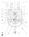
- FIG. 2 shows a longitudinal section through the escalator in Area of the non-driven step belt deflection station 6 with the step guiding device 17, and FIG. 3 shows the same Area as a section through the escalator along the Line III-III in Fig. 2.
- the two front guide rollers 8 With 7 are the steps of the step band referred to, the two front guide rollers 8 and have two rear guide rollers 9. Levels 7 are via extensions of the roller axles 10 of the front guide rollers 8 coupled to two rotating transport chains 11. One of the two can be seen in FIGS. 2 and 3 Conveyor chain idlers 12 on the common Deflection axis 13 are fixed.
- the deflection axis 13 is in Movable in the direction of arrow 14, so that after completion Assembly of the escalator, the transport chains 11 tensioned and later the chain elongation caused by the operation can be balanced.
- 15 is an adjusting spindle schematically indicated a tensioning device, which for Moving the movable axle bearing 16 of the above Deflection axis 13 is used.
- step guidance device 17 shown, which essentially consist of two plate-shaped Side plates 18 with the first mounted thereon Roller guide elements 19 for the front guide rollers 8 and to these laterally offset second roller guide elements 20 for the rear guide rollers 9 there.
- the two side plates 18 are between two transport chain deflection wheels 12 arranged and on one with the supporting structure 2 rigidly connected cross member 22, in the direction of Arrow 14 slidably supported, two vertical guides 23 ensure their vertical position.
- Any of these Side shields 18 have a semi-circular plate cutout 24 on and is in this area over a first Flange 26 of a bearing housing 25 and via a roller bearing 28 with the deflection axis 13 of the two transport chain deflection wheels 12 coupled. This will move the Deflection axis 13 for tensioning the transport chain 11 a relative displacement between the transport chain deflection wheels 12 and the roller guide members attached to the side plates 18 19, 20 avoided.
- Fig. 4 shows details of the mentioned roller bearing connection between each a side plate 18 and the deflection axis 13 of the Transport chain deflecting wheels.
- This roller bearing connection essentially comprises a bearing housing 25 consisting of a first flange 26 and a second, hollow cylindrical Flange 27, the front in the assembled state are flanged together by means of connecting screws 34, and a split roller bearing 28, each consisting of two half-shell-shaped Halves of an inner ring 29, an outer ring 30 and a rolling element cage 31 and from the in Rolling element cage 32. Construction details this split roller bearing 28 are not shown here, because it is a commercially available construction element is.
- the half-shell halves of one such roller bearings are in the radial direction on the deflection axis 13 mountable and removable from this. In the event of a bearing defect, this roller bearing can therefore be replaced without having to remove the deflection axis 13.
- Around to carry out such a bearing change becomes the second Flange 27 detached from the first flange 26 and axially from Inner ring of the rolling bearing 28 deducted, so that it is free is accessible.
- the A replacement bearing is installed in the reverse order.
- the two halves of the inner rings 29 of the two roller bearings 28 sit in a recess 33 of the deflection axis 13 and are thus axially fixed in an ideal manner.
- Fig. 5 shows a second application example for divided Rolling bearings in escalators.
- Split roller bearings serve here as Storage of a transport chain drive wheel unit 4, containing two torsionally rigid with each other via a hollow shaft 41 connected transport chain drive wheels 42 that drive the conveyor chains 11, which together with the Steps 7 form the step belt 3.
- the transport chain drive wheel unit 4 is over two divided roller bearings 43 on a non-rotating, at their ends in the supporting structure 2 of the escalator 1 fixed central axis 44 supported. 5 are in bearing seats 45 of the hubs 46 of the transport chain drive wheels 42 installed. Instead of in the hubs 46 of the conveyor chain drive wheels 42, these bearing seats could also be in the end flanges 47 of the hollow shaft 41 can be integrated.
- a split roller bearing 43 can be replaced, without the escalator 1 in the area of the transport chain drive wheel unit 4 must be accessible from the side and without the latter having to be dismantled or the transport chains 11 of the transport chain drive wheels 42 too are remove. There are only two or three stages 7 disassembled from the transport chains 11 to the area of Bearing points accessible from the inside of the escalator close.
- set screws 49 In the transition area between the middle part of the hollow shaft 41 and its bell-shaped extensions are radial arranged set screws 49 can be seen. With these set screws 49 the hollow shaft is replaced before a rolling bearing replacement 41 with the transport chain drive wheels 42 opposite the Central axis 44 supported so that during the bearing replacement perfect centering of the transport chain drive wheel unit 4 is retained.
- the hollow shaft 41 is in the vicinity of its two end flanges 47 expanded bell-shaped and with three reach openings 48 provided through which to remove and install the shared rolling bearing 43 required manipulations and the components of the rolling bearing 43 removed or Installation site to be added.
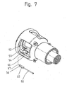
- Detail A shows a pulling aid 52 for pulling out the outer ring 53 of the shared rolling bearing 43. This detail is related with Fig. 7 described in more detail.
- Fig. 6 shows how the bearing cap 50 by removing the Bearing cap screws 51 is loosened so that it is on the Central axis shifted or, if the bearing cap 50. is designed in two parts, through the through openings 48 can be removed.
- Fig. 7 and detail A in Fig. 5, show how using pulling aids 52 the outer ring 53 of the split roller bearing 43 is pulled out of its bearing seat 45.
- the hub 46 of the transport chain drive wheel, not shown here 42 are around the bearing seat 45 therein 45 parallel bores 54 are arranged on the axis of this bearing seat. The peripheries of these holes. 54 intersect the Periphery of the bearing seat 45 so that between each bore 54 and the bearing seat 45 to the axis of the bearing seat 45 parallel slot exists.
- each bore 54 is before mounting the roller bearing 43 is essentially cylindrical Pull-out tool 52 used, which is an axial Contains internal thread, in which a pull-out screw is required 55 is introduced.
- the pull-out aid 52 points in parallel a flat 56 on its axis, which prevents that the cylindrical body in the area of the Bearing seat 45 protrudes, the flattening in Longitudinal direction extends only so far that at one end of the Extraction tool 52 the full cylinder diameter in Form of a kind of nose 57 is preserved.
- This nose 57 engages behind the lower end of the bearing seat 45 of the Outer ring 53 of the roller bearing 43.
- all pull-out screws 55 are first so far screwed in that with its front end at the bottom of the Bore holes 54 so that when turning the Extraction tool 52 pressed out of the holes 54 be and with their nose 57 the outer ring 53 and thus pull the entire rolling bearing 43 out of the bearing seat 45.
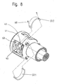
- FIG. 8 shows how the bearing seat 45 pulled out roller bearing 43 by removing the outer eye bolts 60 the outer ring 53 in two half shells 53.1 and 53.2, which is then divided through the access openings 48 removed from the area of the hollow shaft 41 become.
- Fig. 9 shows how after the disassembly of the outer ring 53 of divided into two rolling element cage halves 61.1 and 61.2 Rolling body cage 61 with its rolling bodies 62 through the Passage openings 48 are removed.
- Fig. 10 it can be seen how the last component of the dismantling, divided roller bearing 43 of which on the Central axis 44 seated inner ring 63 by loosening the Inner eye bolts 64 in two half shells 63.1 and 63.2 divided and through the access openings 48 from the area the hollow shaft 41 is removed.
Landscapes
- Escalators And Moving Walkways (AREA)
Abstract
Description
- Fig. 1
- zeigt eine generelle Anordnung einer Fahrtreppe.
- Fig. 2
- zeigt den Bereich der nicht angetriebenen Stufenband-Umlenkstation mit der Stufenführungseinrichtung und der verschiebbaren Umlenkachse als Längsschnitt durch die Fahrtreppe.
- Fig.3
- zeigt den Bereich der nicht angetriebenen Stufenband-Umlenkstation mit der Stufenführungseinrichtung, der verschiebbaren Umlenkachse und dem die Stufenführungseinrichtung mit der Umlenkachse koppelnden geteilten Wälzlager als Schnitt durch die Fahrtreppe entlang der Linie III-III in Fig. 2.
- Fig. 4
- zeigt die Wälzlageranordnung im Detail, die die Kopplung zwischen Führungseinrichtung und Umlenkachse der Transportketten-Umlenkräder bildet.
- Fig. 5
- zeigt die auf geteilten Wälzlagern gelagerte Transportketten-Antriebsräder-Einheit
- Fig. 6 bis Fig. 10
- zeigen Details zum Ablauf des Austausches eines geteilten Wälzlagers in der Transportketten-Antriebsräder-Einheit
- 1
- Fahrtreppe
- 2
- Tragkonstruktion
- 3
- Stufenband
- 4
- Transportketten-Antriebsrad
- 5
- Antriebseinheit
- 6
- Stufenband-Umlenkstation
- 7
- Stufe
- 8
- Vordere Führungsrolle
- 9
- Hintere Führungsrolle
- 10
- Rollenachse der vorderen Führungsrolle
- 11
- Transportkette
- 12
- Transportketten-Umlenkrad
- 13
- Umlenkachse
- 14
- Pfeil (Achsverschiebung)
- 15
- Verstellspindel zu Spannvorrichtung
- 16
- Verschiebbares Achslager
- 17
- Stufenführungseinrichtung
- 18
- Seitenschild
- 19
- erstes Rollenführungselement
- 20
- zweites Rollenführungselement
- 21
- -
- 22
- Querträger
- 23
- Vertikalführung
- 24
- Plattenausschnitt
- 25
- Lagergehäuse
- 26
- erster Flansch
- 27
- zweiter Flansch
- 28
- Geteiltes Wälzlager
- 29
- Innenring
- 30
- Aussenring
- 31
- Wälzkörperkäfig
- 32
- Wälzkörper
- 33
- Einstich
- 34
- Verbindungsschraube
- 35
- -
- 36
- -
- 37
- Hohlwelle
- 38
- Transportketten-Antriebsräder
- 39
- Geteiltes Wälzlager
- 40
- Zentralachse
- 41
- Lagersitz
- 42
- Nabe
- 43
- Endflansch
- 44
- Durchgreiföffnung
- 45
- Stellschrauben
- 46
- Lagerdeckel
- 47
- Lagerdeckel-Schrauben
- 48
- Auszieh-Hilfsmittel
- 49
- Aussenring 53.1, 53.2 Halbschalen des Aussenrings.
- 50
- Bohrung
- 51
- Ausziehschraube
- 52
- Anflachung
- 53
- Nase
- 54
- -
- 55
- -
- 56
- Aussenringschraube
- 57
- Wälzkörperkäfig 61.1, 61.2 Wälzkörperkäfig-Hälften
- 58
- Wälzkörper
- 59
- Innenring 63.1, 63.2 Halbschalen des Innenrings
- 60
- Innenringschraube
Claims (12)
- Fahrtreppe bzw. Fahrsteig, enthaltend mindestens ein Wälzlager (28; 43), das zwischen einer Achse oder Welle und mindestens einem weiteren Konstruktionselement montiert ist, dadurch gekennzeichnet, dass das Wälzlager (28; 43) ein geteiltes Wälzlager ist.
- Fahrtreppe bzw. Fahrsteig nach Anspruch 1, dadurch gekennzeichnet, dass diese bzw. dieser eine Stufenführungseinrichtung (17) zur Führung von Fahrtreppenstufen (7) bzw. Fahrsteigpaletten aufweist, die über mindestens ein zweigeteiltes Wälzlager (28) mit einer Achse (13) gekoppelt ist.
- Fahrtreppe bzw. Fahrsteig nach Anspruch 2, dadurch gekennzeichnet, dass die Achse (13) quer zu ihrer Achsrichtung verschiebbar ist.
- Fahrtreppe bzw. Fahrsteig nach Anspruch 2 oder 3, dadurch gekennzeichnet, dass das geteilte Wälzlager (28) auf der Achse (13) montiert ist und in einem Lagergehäuse (25) sitzt, das zwei unterschiedlich geformte Flansche (26, 27) umfasst, von denen der eine hohlzylinderförmig ausgebildet ist und das gesamte geteilte Wälzlager (28) aufnimmt.
- Fahrtreppe bzw. Fahrsteig nach Anspruch 4, dadurch gekennzeichnet, dass die Flansche (26, 27) an je einer Stirnfläche aneinandergeflanscht und miteinander verschraubt sind.
- Fahrtreppe bzw. Fahrsteig nach Anspruch 1 oder 2, dadurch gekennzeichnet, dass das geteilte Wälzlager (28) einen Innenring (29) aufweist, wobei der Innenring (29) in einem Einstich (33) in der Achse (13) montiert ist.
- Fahrtreppe bzw. Fahrsteig nach Anspruch 1, dadurch gekennzeichnet, dass diese bzw. dieser Transportketten-Antriebsräder (42) zum Antreiben eines Stufenbands (3) bzw. eines Palettenbands aufweist, dass diese bzw. dieser ein weiteres geteiltes Wälzlager (43) aufweist, wobei die Transportketten-Antriebsräder (42) über die geteilten Wälzlager (43) gelagert sind.
- Fahrtreppe bzw. Fahrsteig nach Anspruch 7, dadurch gekennzeichnet, dass die Transportketten-Antriebsräder (42) über die geteilten Wälzlager (43) auf der Achse (44) gelagert sind, wobei die Achse (44) feststehend ist.
- Fahrtreppe bzw. Fahrsteig nach Anspruch 7 oder 8, dadurch gekennzeichnet, dass die Transportketten-Antriebsräder (42) durch eine Hohlwelle (41) miteinander verbunden sind.
- Fahrtreppe bzw. Fahrsteig nach Anspruch 9, dadurch gekennzeichnet, dass die Hohlwelle (41) in ihren beiden Endbereichen radiale Durchgreiföffnungen (48) aufweist.
- Fahrtreppe bzw. Fahrsteig nach Anspruch 9 oder 10, dadurch gekennzeichnet, dass die Hohlwelle (41) mindestens zwei Gruppen von radial angeordneten Gewinden für Stellschrauben (49) aufweist.
- Fahrtreppe bzw. Fahrsteig nach Anspruch 9, dadurch gekennzeichnet, dass mindestens eines der geteilten Wälzlager (43) in einem Lagersitz (45) montiert ist, wobei das Wälzlager (43) einen Aussenring (53) aufweist, der im Lagersitz (45) festgehalten ist, und wobei um den Lagersitz (45) herum zu dessen Achse parallele Kanäle (54) angeordnet sind, welche Auszieh-Hilfsmittel (52) zum Herausziehen des Wälzlagers (43) aus seinem Lagersitz (45) enthalten, die eine Stirnseite des geteilten Wälzlagers (43) hintergreifen.
Priority Applications (1)
| Application Number | Priority Date | Filing Date | Title |
|---|---|---|---|
| EP20020007477 EP1249425B1 (de) | 2001-04-11 | 2002-04-02 | Geteiltes Wälzlager für Antriebswelle einer Fahrtreppe oder eines Fahrsteiges |
Applications Claiming Priority (3)
| Application Number | Priority Date | Filing Date | Title |
|---|---|---|---|
| EP01810361 | 2001-04-11 | ||
| EP01810361 | 2001-04-11 | ||
| EP20020007477 EP1249425B1 (de) | 2001-04-11 | 2002-04-02 | Geteiltes Wälzlager für Antriebswelle einer Fahrtreppe oder eines Fahrsteiges |
Publications (2)
| Publication Number | Publication Date |
|---|---|
| EP1249425A1 true EP1249425A1 (de) | 2002-10-16 |
| EP1249425B1 EP1249425B1 (de) | 2006-12-20 |
Family
ID=26077367
Family Applications (1)
| Application Number | Title | Priority Date | Filing Date |
|---|---|---|---|
| EP20020007477 Expired - Lifetime EP1249425B1 (de) | 2001-04-11 | 2002-04-02 | Geteiltes Wälzlager für Antriebswelle einer Fahrtreppe oder eines Fahrsteiges |
Country Status (1)
| Country | Link |
|---|---|
| EP (1) | EP1249425B1 (de) |
Cited By (1)
| Publication number | Priority date | Publication date | Assignee | Title |
|---|---|---|---|---|
| EP1616834A3 (de) * | 2004-07-12 | 2006-05-10 | Inventio Ag | Fahrtreppe bzw. Fahrsteig mit Wellenlagerung und Verfahren zur Montage, bzw. Demontage dieser Fahrtreppe |
Citations (2)
| Publication number | Priority date | Publication date | Assignee | Title |
|---|---|---|---|---|
| GB891660A (en) * | 1958-09-26 | 1962-03-14 | Westinghouse Electric Corp | Improvements in or relating to moving stairways |
| US4475777A (en) * | 1981-03-28 | 1984-10-09 | Fag Kugelfischer Georg Schafer & Co. | Split-ring roller bearing |
-
2002
- 2002-04-02 EP EP20020007477 patent/EP1249425B1/de not_active Expired - Lifetime
Patent Citations (2)
| Publication number | Priority date | Publication date | Assignee | Title |
|---|---|---|---|---|
| GB891660A (en) * | 1958-09-26 | 1962-03-14 | Westinghouse Electric Corp | Improvements in or relating to moving stairways |
| US4475777A (en) * | 1981-03-28 | 1984-10-09 | Fag Kugelfischer Georg Schafer & Co. | Split-ring roller bearing |
Cited By (2)
| Publication number | Priority date | Publication date | Assignee | Title |
|---|---|---|---|---|
| EP1616834A3 (de) * | 2004-07-12 | 2006-05-10 | Inventio Ag | Fahrtreppe bzw. Fahrsteig mit Wellenlagerung und Verfahren zur Montage, bzw. Demontage dieser Fahrtreppe |
| CN100450912C (zh) * | 2004-07-12 | 2009-01-14 | 因温特奥股份公司 | 具有轴座的自动扶梯或移动步道及其安装和拆卸方法 |
Also Published As
| Publication number | Publication date |
|---|---|
| EP1249425B1 (de) | 2006-12-20 |
Similar Documents
| Publication | Publication Date | Title |
|---|---|---|
| DE2556691C3 (de) | Fördervorrichtung, insbesondere zum Heben von Lasten | |
| EP0081813A1 (de) | Scheibensatz, insb. in Form eines Werkzeuges für Bodenbearbeitungsgeräte | |
| DE3705752C2 (de) | ||
| DE69402725T2 (de) | Treppenkette für Rolltreppe | |
| DE3522724A1 (de) | Foerderbandrolle mit mindestens einer spiralfoermigen bahn auf der zylindrischen oberflaeche | |
| DE2200523C3 (de) | Drahtseilverbinder | |
| EP0527345B1 (de) | Tragrolle für Förderanlagen, insbesondere Skidanlagen | |
| WO2006029598A1 (de) | Treibscheiben-schachtfördermaschine mit verbesserter kühlluftführung | |
| DE4000232A1 (de) | Kettentrommelverlagerung im maschinenrahmen eines kettenkratzfoerderers | |
| DE19633832C2 (de) | Seilzug mit vereinfachter Montage | |
| EP0563699B1 (de) | Plattenzylinder mit einer verstellbaren Spannschiene | |
| EP1249425B1 (de) | Geteiltes Wälzlager für Antriebswelle einer Fahrtreppe oder eines Fahrsteiges | |
| EP3887301A1 (de) | Verfahren zum montieren einer förderkette für ein palettenband eines fahrsteigs | |
| EP3325379B1 (de) | Antrieb für eine bandförderanlage, verfahren zum montieren eines antriebs an eine bandförderanlage sowie bandförderanlage | |
| DE3131465A1 (de) | "schuettgut-foerderer mit foerderergestell und foerdergurt" | |
| DE19507362C1 (de) | Teigwickelmaschine mit mindestens einer austauschbaren Walze | |
| DE102005053629A1 (de) | Wickelvorrichtung | |
| DE20119584U1 (de) | Tragrolle für eine Rollenbahn | |
| EP0038320B1 (de) | Treibrollengerüst für Stranggiessanlagen | |
| DE20003241U1 (de) | Rollenanordnung für einen Rollenförderer | |
| DE20209091U1 (de) | Rollenanordnung für einen Zwirnkopfrotor | |
| EP1066890A1 (de) | Anordnung zum Wechseln der einen Walzring haltenden Mutter | |
| DE2656773C2 (de) | Vorrichtung zum Verändern des Abstandes zweier einander gegenüberliegender Stütz- bzw. Führungsrollen einer Stranggießanlage | |
| DE7338366U (de) | Geteiltes Zylinderrollenlager | |
| EP0250696B1 (de) | Vorrichtung zur Zu- und/oder Abführung von Betriebsmedien zu bzw. von einem Konverter |
Legal Events
| Date | Code | Title | Description |
|---|---|---|---|
| PUAI | Public reference made under article 153(3) epc to a published international application that has entered the european phase |
Free format text: ORIGINAL CODE: 0009012 |
|
| AK | Designated contracting states |
Kind code of ref document: A1 Designated state(s): AT BE CH CY DE DK ES FI FR GB GR IE IT LI LU MC NL PT SE TR |
|
| AX | Request for extension of the european patent |
Free format text: AL;LT;LV;MK;RO;SI |
|
| 17P | Request for examination filed |
Effective date: 20030324 |
|
| AKX | Designation fees paid |
Designated state(s): AT CH DE FR GB LI |
|
| 17Q | First examination report despatched |
Effective date: 20031201 |
|
| GRAP | Despatch of communication of intention to grant a patent |
Free format text: ORIGINAL CODE: EPIDOSNIGR1 |
|
| GRAS | Grant fee paid |
Free format text: ORIGINAL CODE: EPIDOSNIGR3 |
|
| GRAA | (expected) grant |
Free format text: ORIGINAL CODE: 0009210 |
|
| AK | Designated contracting states |
Kind code of ref document: B1 Designated state(s): AT CH DE FR GB LI |
|
| REG | Reference to a national code |
Ref country code: GB Ref legal event code: FG4D Free format text: NOT ENGLISH |
|
| REG | Reference to a national code |
Ref country code: CH Ref legal event code: EP |
|
| REF | Corresponds to: |
Ref document number: 50208982 Country of ref document: DE Date of ref document: 20070201 Kind code of ref document: P |
|
| GBT | Gb: translation of ep patent filed (gb section 77(6)(a)/1977) |
Effective date: 20070305 |
|
| ET | Fr: translation filed | ||
| PLBE | No opposition filed within time limit |
Free format text: ORIGINAL CODE: 0009261 |
|
| STAA | Information on the status of an ep patent application or granted ep patent |
Free format text: STATUS: NO OPPOSITION FILED WITHIN TIME LIMIT |
|
| 26N | No opposition filed |
Effective date: 20070921 |
|
| PGFP | Annual fee paid to national office [announced via postgrant information from national office to epo] |
Ref country code: AT Payment date: 20080415 Year of fee payment: 7 |
|
| PGFP | Annual fee paid to national office [announced via postgrant information from national office to epo] |
Ref country code: CH Payment date: 20080714 Year of fee payment: 7 |
|
| REG | Reference to a national code |
Ref country code: CH Ref legal event code: PL |
|
| PG25 | Lapsed in a contracting state [announced via postgrant information from national office to epo] |
Ref country code: CH Free format text: LAPSE BECAUSE OF NON-PAYMENT OF DUE FEES Effective date: 20090430 Ref country code: LI Free format text: LAPSE BECAUSE OF NON-PAYMENT OF DUE FEES Effective date: 20090430 Ref country code: AT Free format text: LAPSE BECAUSE OF NON-PAYMENT OF DUE FEES Effective date: 20090402 |
|
| REG | Reference to a national code |
Ref country code: FR Ref legal event code: PLFP Year of fee payment: 15 |
|
| REG | Reference to a national code |
Ref country code: FR Ref legal event code: PLFP Year of fee payment: 16 |
|
| REG | Reference to a national code |
Ref country code: FR Ref legal event code: PLFP Year of fee payment: 17 |
|
| PGFP | Annual fee paid to national office [announced via postgrant information from national office to epo] |
Ref country code: DE Payment date: 20190418 Year of fee payment: 18 |
|
| PGFP | Annual fee paid to national office [announced via postgrant information from national office to epo] |
Ref country code: FR Payment date: 20190424 Year of fee payment: 18 |
|
| REG | Reference to a national code |
Ref country code: DE Ref legal event code: R119 Ref document number: 50208982 Country of ref document: DE |
|
| PG25 | Lapsed in a contracting state [announced via postgrant information from national office to epo] |
Ref country code: FR Free format text: LAPSE BECAUSE OF NON-PAYMENT OF DUE FEES Effective date: 20200430 Ref country code: DE Free format text: LAPSE BECAUSE OF NON-PAYMENT OF DUE FEES Effective date: 20201103 |
|
| PGFP | Annual fee paid to national office [announced via postgrant information from national office to epo] |
Ref country code: GB Payment date: 20210426 Year of fee payment: 20 |
|
| REG | Reference to a national code |
Ref country code: GB Ref legal event code: PE20 Expiry date: 20220401 |
|
| PG25 | Lapsed in a contracting state [announced via postgrant information from national office to epo] |
Ref country code: GB Free format text: LAPSE BECAUSE OF EXPIRATION OF PROTECTION Effective date: 20220401 |