EP1245717A2 - Dampfbügelvorrichtung - Google Patents
Dampfbügelvorrichtung Download PDFInfo
- Publication number
- EP1245717A2 EP1245717A2 EP02005821A EP02005821A EP1245717A2 EP 1245717 A2 EP1245717 A2 EP 1245717A2 EP 02005821 A EP02005821 A EP 02005821A EP 02005821 A EP02005821 A EP 02005821A EP 1245717 A2 EP1245717 A2 EP 1245717A2
- Authority
- EP
- European Patent Office
- Prior art keywords
- steam
- ironing
- ironing board
- board part
- particular according
- Prior art date
- Legal status (The legal status is an assumption and is not a legal conclusion. Google has not performed a legal analysis and makes no representation as to the accuracy of the status listed.)
- Withdrawn
Links
- 238000010409 ironing Methods 0.000 title claims abstract description 100
- XEEYBQQBJWHFJM-UHFFFAOYSA-N Iron Chemical group [Fe] XEEYBQQBJWHFJM-UHFFFAOYSA-N 0.000 claims abstract description 42
- 229910052742 iron Inorganic materials 0.000 claims abstract description 20
- 238000007664 blowing Methods 0.000 claims abstract description 17
- 239000002184 metal Substances 0.000 claims description 9
- 229910052751 metal Inorganic materials 0.000 claims description 9
- 238000007654 immersion Methods 0.000 claims description 8
- 125000006850 spacer group Chemical group 0.000 claims description 5
- 238000004804 winding Methods 0.000 claims description 4
- 230000001154 acute effect Effects 0.000 claims description 3
- 229920001296 polysiloxane Polymers 0.000 claims description 3
- 230000037431 insertion Effects 0.000 claims 1
- 238000003780 insertion Methods 0.000 claims 1
- 239000004753 textile Substances 0.000 description 3
- 238000001816 cooling Methods 0.000 description 1
- 238000005516 engineering process Methods 0.000 description 1
- 239000006261 foam material Substances 0.000 description 1
- 238000000034 method Methods 0.000 description 1
- 238000013021 overheating Methods 0.000 description 1
Images



Classifications
-
- D—TEXTILES; PAPER
- D06—TREATMENT OF TEXTILES OR THE LIKE; LAUNDERING; FLEXIBLE MATERIALS NOT OTHERWISE PROVIDED FOR
- D06F—LAUNDERING, DRYING, IRONING, PRESSING OR FOLDING TEXTILE ARTICLES
- D06F81/00—Ironing boards
- D06F81/08—Ironing boards incorporating heating, steaming, or forced ventilation means
Definitions
- the invention initially relates to a steam ironing device with an ironing board that is air or vapor permeable Has board surface, a steam generator and an air blowing device, one with the steam generator connected iron and a support frame.
- the ironing board part forms a technical unit which, in addition to the steam generator and the air blowing device, preferably also contains the electrical connections and the electrical or electronic control of the iron.
- the iron is connected to this removable technical unit via steam and electrical lines; is therefore part of the same.
- the entire technical unit formed by the ironing board part can be removed from the rest of the ironing board. Accordingly, the steam ironing device is divided into two, which proves to be space-saving when the device is stored.
- the invention further relates to a steam ironing device according to claim 1 or according to the features of the preamble of claim 1, here to increase the effectiveness is suggested that the Air blowing device formed by a fan is, with an impeller, wherein an axis of rotation of the impeller with an ironing board surface an acute angle includes.
- the Air blowing device formed by a fan is, with an impeller, wherein an axis of rotation of the impeller with an ironing board surface an acute angle includes.
- an arrangement is selected where the axis of rotation of the fan impeller is about at an angle of 30 to 60 ° to the ironing board surface is aligned, the ironing board surface is breathable is, for example.
- a storage chamber is designed for the iron, which preferably can be closed with a lid.
- the storage chamber has a metal floor, which more preferably by means of elastic spacers is supported. Spacers are preferred in this regard made of silicone.
- Iron preferably a receiving chamber of the ironing board part is assignable, is preferred if the Electrical and steam lines in the area of the receiving chamber are connected to the technical unit.
- the ironing board part it turns out to be advantageous in the ironing board part to provide a cable winder.
- the ironing board part one that forms part of the ironing board surface Has lid. The latter covers in the Operating position the storage chamber for the iron.
- the cable winding device is provided in the lid.
- the ironing board part has an immersion section into a receptacle dipped below the remaining ironing board. So can be provided that the ironing board part like a drawer inserted into a corresponding receptacle can be. It has proven to be particularly advantageous here when the immersion section becomes its free Is tapered towards the end, with which one Introductory help is given. To ensure operational security ensure, it is further suggested that the A slot on the remaining ironing board has, for example in the form that reboundable Lugs of the removable ironing board part in corresponding Enter the recesses in the receptacle. This Latching can only be released with emphasis on the will.
- the Fan from an air blowing operation to an air suction operation and vice versa is switchable.
- the air suction operation is used to suck in the textiles to be ironed the ironing board and for cooling the same after the finished Ironing process.
- For dampening difficult zones from textiles is switched to an air blowing mode, to create an air cushion under the one to be damped Creating textile.
- FIG. 1 shows a first embodiment of a steam ironing device 1 with a frame carrying an ironing board 2
- the board surface 4 of the connected to the frame 3 Ironing boards 2 is, as from the representations in the 3 to 7 schematically indicated, from an expanded metal manufactured and is therefore permeable to steam and air.
- This board surface 4 is spanned by a preferably laminated with a foam material Cover 5.
- the ironing board 2 On the underside, the ironing board 2 has, in the usual way Way tapered end opposite end one Recording 6, which is closed on the side and down, however upwards to the air and vapor permeable Board surface 4 is designed open.
- An ironing board part 7 can be inserted into this receptacle 6.
- This ironing board part forming a technical unit 7 has one to be inserted into the receptacle 6 Immersion section 8, which to its free End 9 is tapered.
- the axis of rotation x of the fan impeller with the board surface 4 an acute angle Includes alpha from 30 to 60 °.
- the fan 10 is in an air blowing mode an air suction mode and vice versa switchable.
- Air intake or air discharge is in the, the immersion section 8 receiving recording 6 a corresponding arranged air passage opening 12 is provided.
- This lid 17 is also part of the removable Ironing board part 7.
- a hot iron 15 in the storage chamber 16 has a metal base 18 on.
- the latter is by means of elastic spacers, preferably made of silicone.
- a fuse is provided, which is exceeded when it is exceeded a predetermined limit temperature in the Storage chamber 16 or on the metal floor 18 the Power supply to the iron 15 and optionally of the steam generator interrupts.
- Webs 20 are provided on the underside of the cover 17, to form a cable winding device 21 for the Steam and electric line 14 of the iron 15.
- the removable ironing board part 7 also takes up the whole Electrics or electronics. So is from the representations to recognize that this ironing board part 7 in Range of its free end switch or controller 22 and may have operation indicators.
- FIG. 10 to 13 is the steam ironing device according to the invention 1 shown in a second embodiment, where in Fig. 10 for better illustration of the ironing board part 7 used, the ironing cover omitted and the board surface, which also here is preferably an expanded metal grid, not shown is.
- the design of the device 1 according to FIGS. 10 to 13 essentially corresponds to that described first embodiment.
- the separate ironing board part 7 in the Holder 6 can be held in place.
- the receptacle 6 on the side assigned, two handles 25 are provided. The user can capture this on both sides of the ironing board part 7, wherein an actuation pivots the handle 25 for releasing the ironing board part 7.
- the latter is in the simplest way from the Pull out holder 6.
- the entire technology-containing ironing board part 7 of the remaining ironing board 2 removable.
- the latter is also wider than the usual ironing board in Can be used with a conventional iron.
Landscapes
- Engineering & Computer Science (AREA)
- Textile Engineering (AREA)
- Irons (AREA)
Abstract
Description
Das Bügeleisen ist hierbei, wie aus dem Stand der Technik bekannt, über Dampf- und Elektroleitungen mit dieser abnehmbaren Technikeinheit verbunden; ist somit Teil derselben. Zufolge der erfindungsgemäßen Ausgestaltung kann die gesamte, durch das Bügelbrett-Teil gebildete Technikeinheit von dem übrigen Bügelbrett entfernt werden. Demnach ist eine Zweiteilung der Dampfbügelvorrichtung gegeben, was sich als platzsparend bei einer Lagerung der Vorrichtung erweist.
- Fig. 1
- eine erfindungsgemäße Dampfbügelvorrichtung in Perspektive, eine erste Ausführungsform betreffend;
- Fig. 2
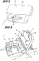
- eine perspektivische Ansicht eines freien Endabschnittes eines abnehmbaren Bügelbrett-Teils;
- Fig. 3
- eine perspektivische Draufsicht auf ein, das abnehmbare Bügelbrett-Teil aufweisende Ende der Dampfbügelvorrichtung, bei geöffneter Aufbewahrungskammer für ein Bügeleisen;
- Fig. 4
- eine der Fig. 3 entsprechende Darstellung, jedoch bei geschlossenem Deckel der Aufbewahrungskammer;
- Fig. 5
- eine der Fig. 4 entsprechende Darstellung, jedoch im Zuge einer Entnahme des abnehmbaren Bügelbrett-Teils von dem verbleibenden Bügelbrett;
- Fig. 6
- eine perspektivische Darstellung des abgenommenen Bügelbrett-Teils sowie des verbleibenden Bügelbretts;
- Fig. 7
- eine perspektivische Unteransicht des verbleibenden Bügelbretts mit einem Traggestell;
- Fig. 8
- eine schematische Längsschnittdarstellung durch das in dem Bügelbrett aufgenommene Bügelbrett-Teil;
- Fig. 9
- eine schematische Schnittdarstellung durch die Aufbewahrungskammer für das Bügeleisen;
- Fig. 10
- eine Dampfbügelvorrichtung in Perspektive unter Fortlassung eines Bügelbrettbezugs und nicht dargestellter Brettfläche, eine zweite Ausführungsform betreffend;
- Fig. 11
- das Bügelbrett-Teil der zweiten Ausführungsform in einer perspektivischen Einzeldarstellung bei geöffnetem Deckel und in der Aufnahmekammer eingesetztem Bügeleisen;
- Fig. 12
- eine weitere perspektivische Darstellung des Bügelbrett-Teils;
- Fig. 13
- eine partiell aufgebrochene Darstellung der Aufnahme der Dampfbügelvorrichtung bei eingesetztem Bügelbrett-Teil.
Claims (13)
- Dampfbügelvorrichtung (1) mit einem Bügelbrett (2), das eine luft- oder dampfdurchlässige Brettfläche (4) aufweist, einem Dampferzeuger und einer Luftblasvorrichtung (11), einem mit dem Dampferzeuger verbundenen Bügeleisen (15) und einem Traggestell (3), dadurch gekennzeichnet, dass der Dampferzeuger und die Luftblasvorrichtung (11) in einem abnehmbaren Bügelbrett-Teil (7) angeordnet sind.
- Dampfbügelvorrichtung nach Anspruch 1 oder nach den Merkmalen des Oberbegriffs des Anspruchs 1, dadurch gekennzeichnet, dass die Luftblasvorrichtung (11) durch einen Ventilator (10) gebildet ist, mit einem Laufrad, wobei eine Drehachse (x) des Laufrades mit einer Bügelbrettfläche (4) einen spitzen Winkel (Alpha) einschließt.
- Dampfbügelvorrichtung nach einem oder mehreren der vorhergehenden Ansprüche oder insbesondere danach, dadurch gekennzeichnet, dass in dem Bügelbrett-Teil (7) eine Aufbewahrungskammer (16) für das Bügeleisen (15) ausgebildet ist.
- Dampfbügelvorrichtung nach einem oder mehreren der vorhergehenden Ansprüche oder insbesondere danach, dadurch gekennzeichnet, dass die Aufbewahrungskammer (16) einen Metallboden (18) aufweist.
- Dampfbügelvorrichtung nach einem oder mehreren der vorhergehenden Ansprüche oder insbesondere danach, dadurch gekennzeichnet, dass der Metallboden (18) mittels elastischer Abstandhalter (19) abgestützt ist.
- Dampfbügelvorrichtung nach einem oder mehreren der vorhergehenden Ansprüche oder insbesondere danach, dadurch gekennzeichnet, dass die Abstandhalter (19) aus Silikon bestehen.
- Dampfbügelvorrichtung nach einem oder mehreren der vorhergehenden Ansprüche oder insbesondere danach, dadurch gekennzeichnet, dass in dem Bügelbrett-Teil (7) eine Kabelwickelvorrichtung (21) vorgesehen ist.
- Dampfbügelvorrichtung nach einem oder mehreren der vorhergehenden Ansprüche oder insbesondere danach, dadurch gekennzeichnet, dass das Bügelbrett-Teil (7) einen, einen Teil der Bügelbrettfläche bildenden Deckel (17) aufweist.
- Dampfbügelvorrichtung nach einem oder mehreren der vorhergehenden Ansprüche oder insbesondere danach, dadurch gekennzeichnet, dass die Kabelwickelvorrichtung (21) in dem Deckel (17) vorgesehen ist.
- Dampfbügelvorrichtung nach einem oder mehreren der vorhergehenden Ansprüche oder insbesondere danach, dadurch gekennzeichnet, dass das Bügelbrett-Teil (7) einen Eintauchabschnitt (8) aufweist, der in eine Aufnahme (6) unterhalb des verbleibenden Bügelbretts (2) eintaucht.
- Dampfbügelvorrichtung nach einem oder mehreren der vorhergehenden Ansprüche oder insbesondere danach, dadurch gekennzeichnet, dass der Eintauchabschnitt (8) zu seinem freien Ende hin sich verjüngend ausgebildet ist.
- Dampfbügelvorrichtung nach einem oder mehreren der vorhergehenden Ansprüche oder insbesondere danach, dadurch gekennzeichnet, dass die Aufnahme (6) an dem verbleibenden Bügelbrett (2) eine Einschubrast aufweist.
- Dampfbügelvorrichtung nach einem oder mehreren der vorhergehenden Ansprüche oder insbesondere danach, dadurch gekennzeichnet, dass der Ventilator (10) von einem Luftblasbetrieb in einen Luftsaugbetrieb und umgekehrt umschaltbar ist.
Applications Claiming Priority (4)
| Application Number | Priority Date | Filing Date | Title |
|---|---|---|---|
| DE10116106 | 2001-03-30 | ||
| DE10116106 | 2001-03-30 | ||
| DE10204745A DE10204745A1 (de) | 2001-03-30 | 2002-02-06 | Dampfbügelvorrichtung |
| DE10204745 | 2002-02-06 |
Publications (2)
| Publication Number | Publication Date |
|---|---|
| EP1245717A2 true EP1245717A2 (de) | 2002-10-02 |
| EP1245717A3 EP1245717A3 (de) | 2004-11-10 |
Family
ID=26008968
Family Applications (1)
| Application Number | Title | Priority Date | Filing Date |
|---|---|---|---|
| EP02005821A Withdrawn EP1245717A3 (de) | 2001-03-30 | 2002-03-14 | Dampfbügelvorrichtung |
Country Status (1)
| Country | Link |
|---|---|
| EP (1) | EP1245717A3 (de) |
Cited By (4)
| Publication number | Priority date | Publication date | Assignee | Title |
|---|---|---|---|---|
| DE10350296A1 (de) * | 2003-10-29 | 2005-06-02 | BSH Bosch und Siemens Hausgeräte GmbH | Trocken und Glättvorrichtung für Kleidungstücke |
| EP1541746A1 (de) * | 2003-12-10 | 2005-06-15 | Crown Technics Ltd. | Dampfbügel-Station |
| EP1705284A1 (de) | 2005-03-22 | 2006-09-27 | Hailo-Werk Rudolf Loh GmbH & Co. KG | Dampfbügeltisch mit Mittel zum Erzeugen einer Luftströmung |
| EP3415684A1 (de) * | 2017-06-12 | 2018-12-19 | Leifheit AG | Dampfbügeltisch |
Family Cites Families (6)
| Publication number | Priority date | Publication date | Assignee | Title |
|---|---|---|---|---|
| DE69113771T4 (de) * | 1990-12-26 | 1997-01-23 | Matsushita Electric Ind Co Ltd | Bügelvorrichtung. |
| DE9406964U1 (de) * | 1994-04-28 | 1994-10-13 | Brüske, geb. Krampitz, Gisela, 40593 Düsseldorf | Bügelvorrichtung |
| DE9411860U1 (de) * | 1994-07-22 | 1995-04-20 | Planeta Hausgeräte GmbH & Co Elektrotechnik KG, 87719 Mindelheim | Bügeltisch mit lösbar befestigtem Dampferzeuger |
| US5582374A (en) * | 1995-05-12 | 1996-12-10 | Fung; Chau C. | Horizontal rest for an iron |
| DE29815078U1 (de) * | 1998-08-21 | 1998-12-17 | Alfred Kärcher GmbH & Co, 71364 Winnenden | Bügeltisch |
| US6212332B1 (en) * | 1998-12-15 | 2001-04-03 | John C. K. Sham | Steam iron station |
-
2002
- 2002-03-14 EP EP02005821A patent/EP1245717A3/de not_active Withdrawn
Cited By (5)
| Publication number | Priority date | Publication date | Assignee | Title |
|---|---|---|---|---|
| DE10350296A1 (de) * | 2003-10-29 | 2005-06-02 | BSH Bosch und Siemens Hausgeräte GmbH | Trocken und Glättvorrichtung für Kleidungstücke |
| EP1541746A1 (de) * | 2003-12-10 | 2005-06-15 | Crown Technics Ltd. | Dampfbügel-Station |
| EP1705284A1 (de) | 2005-03-22 | 2006-09-27 | Hailo-Werk Rudolf Loh GmbH & Co. KG | Dampfbügeltisch mit Mittel zum Erzeugen einer Luftströmung |
| EP1726710A3 (de) * | 2005-03-22 | 2013-07-31 | Leifheit AG | Dampfbügeltisch mit Mitteln zum Erzeugen eines Luftstroms |
| EP3415684A1 (de) * | 2017-06-12 | 2018-12-19 | Leifheit AG | Dampfbügeltisch |
Also Published As
| Publication number | Publication date |
|---|---|
| EP1245717A3 (de) | 2004-11-10 |
Similar Documents
| Publication | Publication Date | Title |
|---|---|---|
| DE69805911T2 (de) | Erwärmungskocher | |
| DE10000569C2 (de) | Sicherheitsvorrichtung für einen Mikrowellenofen | |
| DE69828570T2 (de) | Luftzirkulationsstruktur für Mikrowellenofen | |
| DE102021212765A1 (de) | Haushaltsgargerät | |
| WO2009092649A2 (de) | Hausgerätekombination mit mindestens zwei hausgeräten sowie verfahren zu ihrem betrieb | |
| DE1808694A1 (de) | Geraeteschrank mit Belueftung | |
| DE102020210564B4 (de) | Dunstabzugsvorrichtung und Verfahren zum Entfernen eines Umluftfilters | |
| DE10204745A1 (de) | Dampfbügelvorrichtung | |
| DE2438814A1 (de) | Elektrohandbohrmaschine | |
| EP2459041B1 (de) | Staubsauger mit staubabscheideeinheit | |
| DE3922754A1 (de) | Geschirrspuelmaschine mit einer vorrichtung fuer definiertes oeffnen der tuer | |
| DE102008043362B4 (de) | Hausgerät mit versenkbarem Türgriff | |
| DE202009007297U1 (de) | Staubsauger | |
| DE102007001757A1 (de) | Nebenluftblende für Staubsauger | |
| WO2019081265A1 (de) | Kombinationsgerät mit dunstabzugsvorrichtung und kochfeld | |
| DE3340543A1 (de) | Haushaltgeraet mit einem bedienungsfeld | |
| BE1030368B1 (de) | Dunstabzug | |
| EP1726710A2 (de) | Dampfbügeltisch mit Mitteln zum Erzeugen eines Luftstroms | |
| DE102010063209A1 (de) | Backofentür | |
| DE102009035601A1 (de) | Staubsauger mit Verriegelungseinheit | |
| EP4001499B1 (de) | Filteranordnung für eine wäschebehandlungsmaschine und wäschebehandlungsmaschine | |
| AT105751B (de) | Anlaßschaltkasten für Elektromotoren. | |
| DE9318891U1 (de) | Schutzvorrichtung | |
| DE9208078U1 (de) | Bügelvorrichtung zum Kleider- und Wäschebügeln | |
| DE102024104653A1 (de) | System mit einem Haushaltsgerät sowie Verfahren zum Betrieb eines Systems |
Legal Events
| Date | Code | Title | Description |
|---|---|---|---|
| PUAI | Public reference made under article 153(3) epc to a published international application that has entered the european phase |
Free format text: ORIGINAL CODE: 0009012 |
|
| AK | Designated contracting states |
Kind code of ref document: A2 Designated state(s): AT BE CH CY DE DK ES FI FR GB GR IE IT LI LU MC NL PT SE TR |
|
| AX | Request for extension of the european patent |
Free format text: AL;LT;LV;MK;RO;SI |
|
| PUAL | Search report despatched |
Free format text: ORIGINAL CODE: 0009013 |
|
| AK | Designated contracting states |
Kind code of ref document: A3 Designated state(s): AT BE CH CY DE DK ES FI FR GB GR IE IT LI LU MC NL PT SE TR |
|
| AX | Request for extension of the european patent |
Extension state: AL LT LV MK RO SI |
|
| RIC1 | Information provided on ipc code assigned before grant |
Ipc: 7D 06F 75/12 B Ipc: 7D 06F 81/08 A |
|
| PUAF | Information related to the publication of a search report (a3 document) modified or deleted |
Free format text: ORIGINAL CODE: 0009199SEPU |
|
| D17D | Deferred search report published (deleted) | ||
| 17P | Request for examination filed |
Effective date: 20050506 |
|
| PUAL | Search report despatched |
Free format text: ORIGINAL CODE: 0009013 |
|
| AK | Designated contracting states |
Kind code of ref document: A3 Designated state(s): AT BE CH CY DE DK ES FI FR GB GR IE IT LI LU MC NL PT SE TR |
|
| AX | Request for extension of the european patent |
Extension state: AL LT LV MK RO SI |
|
| AKX | Designation fees paid |
Designated state(s): AT CH DE ES FR IT LI |
|
| 17Q | First examination report despatched |
Effective date: 20090331 |
|
| STAA | Information on the status of an ep patent application or granted ep patent |
Free format text: STATUS: THE APPLICATION IS DEEMED TO BE WITHDRAWN |
|
| 18D | Application deemed to be withdrawn |
Effective date: 20090811 |