EP1244488B1 - Katheter mit umspritzter nabe und verfahren zur herstellung - Google Patents
Katheter mit umspritzter nabe und verfahren zur herstellung Download PDFInfo
- Publication number
- EP1244488B1 EP1244488B1 EP00977237A EP00977237A EP1244488B1 EP 1244488 B1 EP1244488 B1 EP 1244488B1 EP 00977237 A EP00977237 A EP 00977237A EP 00977237 A EP00977237 A EP 00977237A EP 1244488 B1 EP1244488 B1 EP 1244488B1
- Authority
- EP
- European Patent Office
- Prior art keywords
- hub
- catheter
- sleeve
- polymeric
- shaft
- Prior art date
- Legal status (The legal status is an assumption and is not a legal conclusion. Google has not performed a legal analysis and makes no representation as to the accuracy of the status listed.)
- Expired - Lifetime
Links
Images

Classifications
-
- A—HUMAN NECESSITIES
- A61—MEDICAL OR VETERINARY SCIENCE; HYGIENE
- A61M—DEVICES FOR INTRODUCING MEDIA INTO, OR ONTO, THE BODY; DEVICES FOR TRANSDUCING BODY MEDIA OR FOR TAKING MEDIA FROM THE BODY; DEVICES FOR PRODUCING OR ENDING SLEEP OR STUPOR
- A61M25/00—Catheters; Hollow probes
- A61M25/0009—Making of catheters or other medical or surgical tubes
- A61M25/0014—Connecting a tube to a hub
-
- A—HUMAN NECESSITIES
- A61—MEDICAL OR VETERINARY SCIENCE; HYGIENE
- A61M—DEVICES FOR INTRODUCING MEDIA INTO, OR ONTO, THE BODY; DEVICES FOR TRANSDUCING BODY MEDIA OR FOR TAKING MEDIA FROM THE BODY; DEVICES FOR PRODUCING OR ENDING SLEEP OR STUPOR
- A61M25/00—Catheters; Hollow probes
- A61M25/0009—Making of catheters or other medical or surgical tubes
-
- B—PERFORMING OPERATIONS; TRANSPORTING
- B29—WORKING OF PLASTICS; WORKING OF SUBSTANCES IN A PLASTIC STATE IN GENERAL
- B29C—SHAPING OR JOINING OF PLASTICS; SHAPING OF MATERIAL IN A PLASTIC STATE, NOT OTHERWISE PROVIDED FOR; AFTER-TREATMENT OF THE SHAPED PRODUCTS, e.g. REPAIRING
- B29C45/00—Injection moulding, i.e. forcing the required volume of moulding material through a nozzle into a closed mould; Apparatus therefor
- B29C45/14—Injection moulding, i.e. forcing the required volume of moulding material through a nozzle into a closed mould; Apparatus therefor incorporating preformed parts or layers, e.g. injection moulding around inserts or for coating articles
- B29C45/14598—Coating tubular articles
-
- B—PERFORMING OPERATIONS; TRANSPORTING
- B29—WORKING OF PLASTICS; WORKING OF SUBSTANCES IN A PLASTIC STATE IN GENERAL
- B29L—INDEXING SCHEME ASSOCIATED WITH SUBCLASS B29C, RELATING TO PARTICULAR ARTICLES
- B29L2031/00—Other particular articles
- B29L2031/753—Medical equipment; Accessories therefor
- B29L2031/7542—Catheters
-
- Y—GENERAL TAGGING OF NEW TECHNOLOGICAL DEVELOPMENTS; GENERAL TAGGING OF CROSS-SECTIONAL TECHNOLOGIES SPANNING OVER SEVERAL SECTIONS OF THE IPC; TECHNICAL SUBJECTS COVERED BY FORMER USPC CROSS-REFERENCE ART COLLECTIONS [XRACs] AND DIGESTS
- Y10—TECHNICAL SUBJECTS COVERED BY FORMER USPC
- Y10S—TECHNICAL SUBJECTS COVERED BY FORMER USPC CROSS-REFERENCE ART COLLECTIONS [XRACs] AND DIGESTS
- Y10S128/00—Surgery
- Y10S128/06—Intravenous injection support
-
- Y—GENERAL TAGGING OF NEW TECHNOLOGICAL DEVELOPMENTS; GENERAL TAGGING OF CROSS-SECTIONAL TECHNOLOGIES SPANNING OVER SEVERAL SECTIONS OF THE IPC; TECHNICAL SUBJECTS COVERED BY FORMER USPC CROSS-REFERENCE ART COLLECTIONS [XRACs] AND DIGESTS
- Y10—TECHNICAL SUBJECTS COVERED BY FORMER USPC
- Y10S—TECHNICAL SUBJECTS COVERED BY FORMER USPC CROSS-REFERENCE ART COLLECTIONS [XRACs] AND DIGESTS
- Y10S128/00—Surgery
- Y10S128/26—Cannula supporters
Definitions
- the present invention relates to guide, diagnostic, and therapeutic catheters for use in medical procedures.
- the present invention relates to an improved therapeutic micro-catheter proximal hub and method of manufacture, wherein the hub is molded around the catheter shaft over a shielding sleeve which prevents damage to the catheter shaft while assuring adequate bonding of the hub to the shaft.
- the present invention relates to the field of catheterization of lumens within the human body, particularly lumens in the cerebral, peripheral, and heart vasculature.
- the invention has application to the manufacture and construction of guide, diagnostic, and drug delivery catheters, as well as balloon catheters.
- Many medical procedures include the insertion of a catheter into a lumen of a living body.
- guide catheters and diagnostic catheters are well known for use in catheterization procedures in the vascular system, such as angiography, angioplasty, and other diagnostic or interventional procedures, such as interventional radiology.
- intravascular catheters One useful therapeutic application of intravascular catheters is the treatment of intracranial aneurysms in the brain. Approximately 25,000 intracranial aneurysms rupture each year in North America. An aneurysm which is likely to rupture, or one which has already ruptured, may be treated by delivering an embolic device or agent to the interior of the aneurysm. The embolic device or agent encourages the formation of a thrombus inside the aneurysm. The formation of a thrombus reduces the probability that an aneurysm will rupture. The formation of a thrombus also reduces the probability that a previously ruptured aneurysm will re-bleed.
- Thrombus agents which may be used include liquid thrombus agents such as cyanocrylate, and granulated thrombus agents such as polyvinyl alcohol or alcohol.
- An additional type of thrombus agent which is frequently used is a tiny coil. Any of the thrombus agents described above may be delivered using an intravascular catheter.
- the catheter tip When treating an aneurysm with the aid of an intravascular catheter, the catheter tip is typically positioned proximate the aneurysm site.
- the thrombus agent is then urged through the lumen of the intravascular catheter and introduced into the aneurysm. Shortly after the thrombus agent is placed in the aneurysm, a thrombus forms in the aneurysm and is shortly thereafter complemented with a collagenous material which significantly lessens the potential for aneurysm rupture.
- the lumen of the catheter provides a path for delivering embolic devices to an aneurysm. To this end, it is desirable that the pathway through the catheter have a low friction surface.
- diagnostic catheters are used for procedures including dye delivery, arterial flushing or arterial pressure monitoring. Diagnostic catheters are also used during cardiac catheterization for diagnosis of coronary artery disease, for defining vessel anatomy, for isolating lesions, and for identifying adjacent cardiac branches which may impinge on a lesion and affect ventricular function.
- the distal end of the diagnostic catheter is inserted percutaneously into the vascular system of the patient and pushed distally up and over the aortic arch.
- a proximal end of the catheter protrudes outside of the patient's body and may be used for implementation of diagnostic procedures, such as dye delivery, flushing, and arterial pressure monitoring.
- Angioplasty procedures have gained wide acceptance as an efficient and effective method for treating certain types of vascular diseases.
- angioplasty is widely used for stenoses in the coronary arteries, although it is also used for the treatment of stenoses in other parts of the vascular system.
- the most widely used form of angioplasty makes use of a dilatation balloon catheter to treat a stenosis and thereby reestablish an acceptable blood flow through the artery.
- the dilatation catheter includes an elongated tubular shaft and an inflatable balloon carried at a distal end of the shaft. In operation, the catheter is inserted through a guide catheter which has been previously introduced into a patient's vascular system from a location remote from the heart (e.g., femoral artery).
- the proximal end of the guide catheter remains outside the patient while the distal end of the guide catheter is positioned at the coronary artery ostium.
- a dilatation catheter is introduced into the proximal end of the guiding catheter and advanced to the distal end of the guide catheter. Then, by using fluoroscopy, the physician guides the dilatation catheter the remaining distance through the vascular system until the balloon is positioned across the stenosis.
- the catheter commonly includes a hub and/or manifold at its proximal end, which permits the catheter to be more easily handled, and which may incorporate a luer fitting or other connection device which may be attached to an appliance conveying a fluid media or substance which is to be delivered to the distal end of the catheter.
- hubs are adhesively bonded to the catheter shaft, while in other known designs, hubs are injection or insert molded onto the catheter shafts. With the insert molding process, the injected molten plastic hub material, because of its high temperature, may be capable of damaging the shaft of the catheter by melting or otherwise deforming it. This may compromise the integrity of the lumen walls in the affected region which may lead to collapse by kinking or other deformation that reduces the lumen diameter.
- the catheter shaft was afforded protection from the high temperatures of the injected hub material by protective layers placed over the catheter shafts.
- the catheter shaft might be protected by multiple layers of polymeric films over the catheter shaft in the region of hub attachment.
- these multiple protective layers require separate lamination of each layer to the shaft and to each other. Accordingly, these prior methods of securing hubs to catheter shafts had a number of drawbacks.
- the preparation of the catheter shaft prior to hub molding increased the complexity of catheter manufacture, and the increased preparatory steps afforded increased chances for error, quality variations, and rejected products and waste, in addition to increased time and cost of manufacture.
- US 3,720,210 discloses an indwelling catheter device comprising an elongated, flexible tube section of a first material having a through passage way and an enlarged integral flange adjacent one end thereof.
- the enlarged integral flange comprises a portion of the flexible tube section which first extends outwardly from and then is reversely bent relative to the remainder of the flexible tube section, a tubular collar member mounted over the elongated flexible tube section and in fluid-tight relation thereto adjacent the enlarged integral flange, and a molded hub element of a second material not easily bonded to the tube section material completely surrounding the tubular collar member and the enlarged integral flange of the elongated flexible tube section in interlocked and bonded relationship thereto.
- the hub element has an opening extending from one end thereof which communicates with the passage way of the elongated flexible tube section for the conveyance of fluids therethrough.
- FR-A-2.092.970 discloses a similar construction.
- the present invention is defined by the features of the claims and generally pertains to a process for the production of intralumenal catheters with an insert molded hub, that does not require extensive preparation of the catheter shaft prior to molding.
- One embodiment of the present invention provides for a tubular sleeve of material that is compatible with the hub molding media.
- the tubular sleeve shields the catheter shaft from heat generated during the injection molding process, but transfers enough heat for bonding the sleeve to the catheter shaft.
- the compatible material of the tubular sleeve thermally bonds with the shaft on the sleeve's inner diameter, and bonds with the hub molding media on the sleeve's outer diameter during the single injection molding step.
- the present invention overcomes disadvantages of previously existing methods for securing the hub to the catheter shaft, and accomplishes hub molding with fewer errors in manufacture.
- the present invention therefore increases the reliability of the production process, in addition to making the hub to catheter shaft transition seamless, i.e., without weld lines, and therefore more securely affixed to the catheter shaft and less prone to failure or bursting.
- fewer additional materials are introduced into production of the catheter.
- One embodiment of the present invention is a catheter with a flexible, elongate tubular shaft.
- This shaft has a lumen therethrough, and has a proximal and a distal end.
- the catheter shaft may be of any length required to reach the site of therapeutic or diagnostic activity within the patient vasculature, and may also incorporate various therapeutic or diagnostic devices or means at the distal end of the catheter shaft, including an expandable balloon, for example.
- a hub with an inner lumen is attached to the proximal end of the shaft.
- a thin polymeric sleeve covers the proximal end of the catheter shaft, and may extend slightly beyond the proximal end of the catheter shaft.
- This polymeric sleeve is preferably heat fused to the catheter shaft, and is covered over most of its length by the molded hub of the catheter. Generally, the tubular sleeve must extend over any part of the catheter shaft that will be contacted by the hot melt injection during hub molding.
- the hub injectate material is a polymer such as polyamide, nylon, polyether block amide (PEBA), or mixtures and copolymers thereof.
- PEBA polyether block amide
- a preferred commercially available suitable material is Grilamid® TR55LX produced by EMS-Chemie Holding AG/American Grilon, Inc. of Sumter, South Carolina.
- the protective sleeve placed over the catheter shaft is made from the identical material.
- any compatible material for the sleeve will support the subject invention.
- a compatible material it is meant that the sleeve material will form a thermal bond to the shaft, and will also bond to the hot injectate during the molding process.
- the injectate provides sufficient heat to form the sleeve bond to the shaft by conduction therethrough.
- the sleeve and injectate material are both clear or optically clear to form a unitary clear hub.
- the catheter shaft is made with an inner layer of a fluoropolymer or thermoplastic, and an outer layer of a thermoplastic such as a polyether block amide (PEBA)
- the polymeric sleeve will have a wall thickness within a range of approximately 127 ⁇ m to 508 ⁇ m (0.005 inches to 0.020 inches), while the injectate hub hot media will be heated and injected at a temperature of approximately 232°C to 288°C (450° F to 550° F).
- the hot media is preferably cooled by conduction via a recirculating coolant.
- the parameters must be regulated so as to ensure an effective heat bond between the inner diameter of the polymeric sleeve and the outer wall of the catheter shaft, but without permitting excessive heat to be conveyed to the catheter shaft so as to permit damage to the shaft.
- Another embodiment of the present invention incorporates a flexible strain relief sheathing, surrounding the catheter shaft distal to the area of the hub, but in close proximity to the hub, to prevent crimping and to help prevent a degree of bending that may damage the shaft in the area where it meets the hub.
- the strain relief is flexible, but not as flexible as the shaft in the area distal to the hub.
- the flexible strain relief becomes more difficult to flex as it is flexed, and becomes very difficult to flex as it approaches a degree of flexion wherein the shaft surrounded by the strain relief is near its limit of flexion, i.e., at a point where it is in danger of kinking or folding.
- the flexible strain relief is added to the hub after molding and curing of the hub is complete.
- the strain relief may be made from a polymeric material different than that from which the hub is made.
- an integral strain relief that is molded as part of, or as an extension of, the hub itself may be utilized.
- An integrated hub and strain relief is disclosed in commonly assigned pending U.S. Patent Application Serial No. 08/971,456, filed November 17, 1997 , entitled “Integral Hub and Strain Relief,” the disclosure of which is hereby incorporated by reference.
- the polymeric sleeve placed around the catheter shaft will naturally be longer, because the material that is to adhere to the catheter shaft, i.e., the hub and strain relief integrated structure, is longer than the hub structure alone. Because the strain relief, when injection molded, will be at a temperature that may damage the catheter shaft, the polymeric sleeve must be extended to protect the catheter shaft from this additional molded member. When the strain relief member is integrated with the hub, the polymeric sleeve is used to adhere the integral molded hub and strain relief structure to the catheter shaft, in the same way that the sleeve is used to bond the hub to the shaft in the embodiments of the invention previously discussed.
- the present invention further includes a method for manufacturing the hub, and the attendant attachment of the sleeve and hub to the catheter shaft.
- a method for manufacturing the hub, and the attendant attachment of the sleeve and hub to the catheter shaft With this method, the proximal end of the catheter shaft is placed over a pin in a molding core. Thereafter, a polymeric tubular sleeve is placed over the catheter shaft, and is slid down the catheter shaft to the proximal end.
- the polymeric sleeve may extend just beyond the proximal tip of the catheter shaft, or may be flush with the proximal tip.
- the distal end of the polymeric sleeve may be flush with the distal end of the catheter hub as defined by the mold, or, in a preferred embodiment, may extend slightly distally of the distal end of the catheter hub.
- the polymeric material of the catheter hub is injected into the molding core or cavity in which the catheter shaft has been placed.
- the heat of the molten hub material imparts sufficient heat to the polymeric sleeve to fuse the polymeric sleeve to the catheter shaft, and to fuse the polymeric sleeve with the hub itself into one unified member; however, the polymeric sleeve is sufficiently thick so that the heat from the molten hub material does not melt or otherwise deform or damage the catheter shaft.
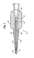
- Figure 1 depicts a proximal portion of a catheter 101 of the subject invention, showing the hub 102, the catheter shaft 103, and the polymeric sleeve 104.
- the polymeric sleeve 104 is shown as a distinct separate member. Insert molding of the hub 102 over the sleeve will, however, reduce or eliminate the distinctiveness of this element, especially when the same polymer is used for the sleeve 104 and hub 102.
- Figure 1 shows the separate elements so that the function of the sleeve 104 as a heat shield for the shaft may be better understood.
- the hub lumen 105 is in fluid communication with the catheter shaft lumen 106, with an intermediate lumen 107 of the polymeric sleeve, if the polymeric sleeve extends past the proximal end of the catheter shaft 103, as is depicted.
- the distal end of the catheter shaft is not depicted, but may be an infusion catheter, a balloon angioplasty catheter, or other diagnostic or therapeutic catheter.
- a strain relief member 108 is used to prevent kinking and bending of catheter shaft 103. This strain relief may be press fit onto the catheter hub after molding, and is held in place by the radial depression 109 in the hub.
- the strain relief member 108 may be integrated with the catheter hub 102 to form an integrated hub and strain relief member.
- the polymeric sleeve 104 would preferably extend to a further distal point at least to the distal end 110 of the strain relief member 108.
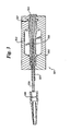
- Figure 2 is a detailed view of the catheter hub 102 of Figure 1, showing the fusion of the catheter hub and polymeric sleeve resulting from injection molding of the catheter hub 102.
- Figure 2 shows generally a hub assembly 201 according to one embodiment of the subject invention. While the subject invention is depicted in Figure 1 with the polymeric sleeve 104 and the catheter hub 102 as separate structures, after the molding process, a preferred embodiment results in a fusion of the two structures into a single unified structure 202, fused to the catheter shaft 203. In a preferred embodiment, the fusion or unification of the two structures; the polymeric sleeve 104 and the catheter hub 102 is so complete so as to have no discernable seam or weld line.
- the polymeric sleeve 104 is separate and distinct from the catheter hub 102, in the finished article, these would appear as a single structure made from a uniform material.
- the polymeric sleeve 104 was separate from the catheter hub 102, as might be seen for an instant following injection of the molten hub material.
- the polymeric sleeve 104 in Figure 1 will quickly fuse to the catheter hub 102, to form an integrated hub and sleeve structure 202.
- the polymeric sleeve 104 surrounds the catheter shaft 103, and may extend distally of the distal end of the catheter hub 102, an artifact of the sleeve 104 is seen as the distal extension 204 of the integrated hub and sleeve structure 202.
- a flexible strain relief member 205 may be placed over the hub extension 204, to form a transitional flexibility between the relatively rigid hub 202 and the relatively flexible unsupported catheter shaft 203.
- This flexible strain relief 205 may be press fit onto the catheter hub and held in place by a ridge 206 which radially encircles the hub 202.
- the flexible strain relief 205 may be formed as an integral structure with the hub 202.
- the polymeric sleeve, seen in Figure 2 as hub extension 204 is preferably lengthened to extend to a point at least as distal as the distal end 206 of the strain relief member 205.
- Figure 3 depicts an injection molding apparatus suitable for use in one embodiment of the subject invention disclosing a method of producing catheters with molded hubs unified with a polymeric sleeve, which is fused to a catheter shaft.
- the injection molding device with a catheter shaft 303 and sleeve assembly 305 inserted therein, is depicted generally at 301.
- the mold is depicted at 302, while the catheter shaft of the catheter being produced by the subject method is depicted at 303.
- the catheter being produced is disposed with its lumen over a holding pin or mandrel 304.
- a polymeric protective sleeve 305 is slid down around the catheter shaft 303, down to the proximal end 306 of the catheter shaft 303, proximate to the molding pin 304.
- the polymeric sleeve may extend proximally to the proximal end 306 of catheter shaft 303, as depicted.
- a suitable molten or otherwise liquid or uncured polymeric substance is injected into the injection mold 302, through injection port 307.
- the catheter shaft 303 may be removed from the holding pin 304.
- the resulting catheter hub formed by injection mold 302 is adhered or fused to polymeric sleeve 305 to form a combined unified structure similar to that depicted in Figure 2.
- the heat of the molten polymeric material, or other aspect of the polymeric material that keeps the molding media liquid or uncured, also serves to make the polymeric sleeve 305 adhere or bond to the catheter shaft 303 by heat bonding of sleeve 305 to the shaft, or by otherwise bringing the polymeric sleeve to an uncured state in which bonding with the catheter shaft 303 is effected.
- the temperature of the molten polymeric material being injected into the molding chamber should be between approximately 232°C and 288°C (450° F and 550° F).
- the melting or uncuring of the polymeric sleeve 305 should effect bonding between the hub structure and the polymeric sleeve to the extent that they form a unified assembly, as discussed previously.
- Both the hub structure material and sleeve material are preferably clear or optically clear.
- Separate strain relief member 308 is depicted in Figure 3, and may be press fit onto the hub formed by mold 302.
- the present invention may be used to manufacture any catheter including a shaft and hub assembly disposed on the proximal end thereof.
- the shafts can include monolithic polymeric shafts or multi-layer shafts which may or may not incorporate a braided reinforcement structure.
- the present invention is particularly useful when used in conjunction with catheter shafts having relatively small diameters and thin tube walls. These features are preferred in catheters which are utilized to reach small vessel lumens because the lumen diameter is optimized to be as large as possible throughout the length of the catheter. As such, the thin wall of the shaft is more susceptible to damage from the molten material during the injection molding process. It is believed that the present invention can be utilized with any combination of polymeric materials which lead to a satisfactory bond strength between the hub, the sleeve, and the outside surface of the catheter shaft. In preferred embodiments, the sleeve and hub material are the same.
- the thickness of the tube wall of the sleeve must be selected in conjunction with several parameters in order for adequate bonds to be formed in the process of the present invention.
- the sleeve thickness must be selected in combination with selecting the temperature of the molten injection material so that there is sufficient heat to cause the inside diameter of the sleeve to bond to the outside diameter of the shaft.
- the sleeve must be thick enough to prevent too much heat to be conducted from the molten polymer to the shaft so that there is damage to the shaft, itself. Experimentation with operating conditions is believed required for each catheter design.
- the shaft sleeve has a wall thickness of about 12.7 ⁇ m to about 508 ⁇ m (about 0.0005 inches to about 0.020 inches), and the injectate has a temperature of about 232°C to about 288°C (about 450° F to about 550° F).
- these parameters are selected in conjunction with a preferred Grilamid® sleeve and hub material, adequate bonds are formed while preventing any damage to the catheter shaft.
- the preceding description of the invention is directed to an infusion catheter, it will be appreciated by those skilled in the art that the invention may be used on other interventional catheters with lumenal or vascular interoperative devices having a hub or manifold, such as atherectomy devices, ultrasonic imaging and therapeutic catheters, laser catheters, stent delivery catheters, and perfusion catheters.
Landscapes
- Health & Medical Sciences (AREA)
- Life Sciences & Earth Sciences (AREA)
- Engineering & Computer Science (AREA)
- Biomedical Technology (AREA)
- Hematology (AREA)
- Biophysics (AREA)
- Pulmonology (AREA)
- Anesthesiology (AREA)
- Veterinary Medicine (AREA)
- Heart & Thoracic Surgery (AREA)
- Public Health (AREA)
- Animal Behavior & Ethology (AREA)
- General Health & Medical Sciences (AREA)
- Mechanical Engineering (AREA)
- Manufacturing & Machinery (AREA)
- Media Introduction/Drainage Providing Device (AREA)
- Injection Moulding Of Plastics Or The Like (AREA)
- Materials For Medical Uses (AREA)
Claims (18)
- Katheteranordnung (101) mit:einem länglichen flexiblen röhrenförmigen Schaft (103; 203) mit einem proximalen Ende und einem distalen Ende, wobei eine Radialwand ein Lumen (106) bildet, das sich zwischen dem proximalen Ende und dem distalen Ende längs erstreckt;einer röhrenförmigen Polymerhülse (104; 204; 305), die auf dem röhrenförmigen Schaft (103; 203; 303) so plaziert ist, daß sie mindestens einen proximalen Abschnitt der Außenfläche der Radialwand des röhrenförmigen Schafts (103; 203; 303) abdeckt, wobei die röhrenförmige Polymerhülse ein proximales Ende, das sich über das proximale Ende des röhrenförmigen Schafts hinaus proximal erstreckt, und ein distales Ende hat, wobei eine Radialwand ein Lumen (107) bildet, das sich zwischen dem proximalen Ende und dem distalen Ende längs erstreckt, wobei die Hülse (104; 204; 305) am distalen und proximalen Ende offen ist, wobei die Hülse (104; 204; 305) mit dem Katheterschaft (103; 203; 303) verschmolzen ist; undeiner Nabe (102) aus einem Polymermaterial, die über der Polymerhülse (104; 204; 305) am proximalen Ende des röhrenförmigen Schafts (103; 203; 303) geformt und mit ihr verschmolzen ist, wobei die Nabe (102) ein Lumen (105) bildet, wobei das Nabenlumen (105) eine Innenwand aufweist, wobei die Nabe (102) um den Katheterschaft (103; 203; 303) angeordnet ist und mindestens einen Teil der Polymerhülse (104; 204; 305) so abdeckt, daß sich das distale Ende der Polymerhülse distal von der Nabe erstreckt.
- Katheter nach Anspruch 1, wobei die Polymerhülse (104; 204; 305) nur einen proximalen Abschnitt der Außenradialwand des röhrenförmigen Schafts (103; 203; 303) abdeckt.
- Katheter nach Anspruch 1, wobei die Polymernabe (102) auf den proximalen Abschnitt des röhrenförmigen Katheterschafts (103; 203; 303) über der Polymerhülse (104; 204; 305) spritzgegossen ist.
- Katheter nach Anspruch 1, wobei die geformte Nabe (102) und die Polymerhülse (104; 204; 305) aus dem gleichen Polymermaterial hergestellt sind.
- Katheter nach Anspruch 4, wobei sowohl das Material der Polymerhülse (104; 204; 305) als auch das der Nabe (102) klar sind.
- Katheter nach Anspruch 4, wobei die Polymerhülse (104; 204; 305) mit dem röhrenförmigen Schaft (103; 203; 303) in mindestens einem proximalen Abschnitt durch Wärme verschmolzen ist.
- Katheter nach Anspruch 3, wobei das Material, aus dem die Nabe (102) hergestellt ist, auf eine Temperatur zwischen 232 °C und 288 °C (450 °F und 550 °F) vor dem Einspritzen in die Naben-Form erwärmt wird.
- Katheter nach Anspruch 7, wobei die geformte Nabe (102) und die Polymerhülse (104; 204; 305) aus einem Material hergestellt sind, das aus der Gruppe ausgewählt ist, die aus Nylon, Polyamid, Polyetherblockamid sowie deren Mischungen oder Copolymeren besteht.
- Katheter nach Anspruch 1, wobei die Polymerhülse (104; 204; 305) und die Nabe (102) zu einer vereinigten Struktur miteinander verschmolzen wurden.
- Katheter nach Anspruch 1, wobei die Polymerschutzhülse eine Radialwanddicke von etwa 127 µm bis 508 µm (0,005 Inch bis 0,020 Inch) hat.
- Katheter nach Anspruch 1, wobei ein flexibles Zugentlastungsteil (108; 205) über dem distalen Teilstück der geformten Nabe (102) angeordnet ist und den Katheterschaft (103; 203; 303) nahe der Nabe (102) und distal dazu umgibt.
- Verfahren zur Bildung einer Anordnung (201) aus einem Katheterschaft (203; 303) und einer Nabe, wobei der Katheterschaft (203; 303) einen länglichen flexiblen röhrenförmigen Schaft (103) hat, der röhrenförmige Schaft ein proximales Ende und ein distales Ende hat, wobei eine Radialwand ein Lumen (106) bildet, das sich zwischen dem proximalen Ende und dem distalen Ende des Schafts (203; 303) längs erstreckt, mit den Schritten:Bereitstellen einer Form (302), die einen Nabenbildenden Hohlraum mit einem sich darin erstreckenden Kernstift (304) hat;Anordnen eines proximalen Abschnitts (306) des Schafts (203; 303) über dem Kernstift (304);Vorschieben einer kurzen röhrenförmigen Polymerhülse (104; 204; 305) über dem Katheterschaft (203; 303) zum proximalen Ende des Katheterschafts (203; 303), so daß sich die röhrenförmige Hülse (104; 204; 305) mindestens bis zum proximalen Ende des Katheterschafts (203; 303) erstreckt und so daß sich die röhrenförmige Hülse (104; 204; 305) zum distalen Ende des Katheterschafts (203; 303) mindestens bis zu einem Punkt erstreckt, bis zu dem sich das distale Ende der Nabe (102) des Katheters erstrecken wird; undEinspritzen eines Polymermaterials in den Formhohlraum über der kurzen röhrenförmigen Polymerhülse (104; 204; 305), wobei Wärme aus dem eingespritzten Polymermaterial bewirkt, daß sich die kurze röhrenförmige Polymerhülse (104; 204; 305) mit dem Schaft (203; 303) und mit dem eingespritzten Material verbindet.
- Verfahren zur Bildung einer Katheterschaft-Naben-Anordnung nach Anspruch 12, wobei die Polymerhülse (104; 204; 305) und die Nabe (102) aus einem Material hergestellt sind, das aus der Gruppe ausgewählt ist, die aus Nylon, Polyamid, Polyetherblockamid sowie deren Mischungen oder Copolymeren besteht.
- Verfahren zur Bildung einer Katheterschaft-Naben-Anordnung nach Anspruch 12, wobei die über dem Katheterschaft (203; 303) plazierte Polymerhülse (104; 204; 305) eine Wanddicke von etwa 127 µm bis 508 µm (0,005 Inch bis 0,020 Inch) hat.
- Verfahren zur Bildung einer Katheterschaft-Naben-Anordnung nach Anspruch 12, wobei das Polymermaterial, aus dem die Nabe (102) gebildet wird, auf eine Temperatur von etwa 232 °C bis 288 °C (450 °F bis 550 °F) erwärmt wird.
- Verfahren zur Bildung einer Katheterschaft-Naben-Anordnung nach Anspruch 12, ferner mit dem Schritt des Abkühlens der Nabe (102) auf eine Temperatur unter 66 °C (150 °F) nach Einspritzabschluß.
- Verfahren zum Anbringen eines Katheterschafts an einer Katheternabe nach Anspruch 12, ferner mit dem zusätzlichen Schritt des Aufpressens eines Polymer-Zugentlastungsteils (108; 205) über einem distalen Abschnitt der Nabe (102) und auf den Katheterschaft (203; 303).
- Verfahren zum Anbringen eines Katheterschafts an einer Katheternabe nach Anspruch 12, wobei die kurze röhrenförmige Polymerhülse (104; 204; 305) und das eingespritzte Polymermaterial klar sind.
Applications Claiming Priority (3)
| Application Number | Priority Date | Filing Date | Title |
|---|---|---|---|
| US09/472,265 US6575959B1 (en) | 1999-12-27 | 1999-12-27 | Catheter incorporating an insert molded hub and method of manufacturing |
| US472265 | 1999-12-27 | ||
| PCT/US2000/031420 WO2001047592A1 (en) | 1999-12-27 | 2000-11-15 | Catheter incorporating an insert molded hub and method of manufacture |
Publications (2)
| Publication Number | Publication Date |
|---|---|
| EP1244488A1 EP1244488A1 (de) | 2002-10-02 |
| EP1244488B1 true EP1244488B1 (de) | 2007-06-27 |
Family
ID=23874797
Family Applications (1)
| Application Number | Title | Priority Date | Filing Date |
|---|---|---|---|
| EP00977237A Expired - Lifetime EP1244488B1 (de) | 1999-12-27 | 2000-11-15 | Katheter mit umspritzter nabe und verfahren zur herstellung |
Country Status (7)
| Country | Link |
|---|---|
| US (1) | US6575959B1 (de) |
| EP (1) | EP1244488B1 (de) |
| JP (1) | JP2003520634A (de) |
| AT (1) | ATE365572T1 (de) |
| CA (1) | CA2395357A1 (de) |
| DE (1) | DE60035368T2 (de) |
| WO (1) | WO2001047592A1 (de) |
Families Citing this family (97)
| Publication number | Priority date | Publication date | Assignee | Title |
|---|---|---|---|---|
| US20040097996A1 (en) | 1999-10-05 | 2004-05-20 | Omnisonics Medical Technologies, Inc. | Apparatus and method of removing occlusions using an ultrasonic medical device operating in a transverse mode |
| US6524251B2 (en) | 1999-10-05 | 2003-02-25 | Omnisonics Medical Technologies, Inc. | Ultrasonic device for tissue ablation and sheath for use therewith |
| US6551337B1 (en) | 1999-10-05 | 2003-04-22 | Omnisonics Medical Technologies, Inc. | Ultrasonic medical device operating in a transverse mode |
| US7214220B2 (en) * | 2001-09-21 | 2007-05-08 | Boston Scientific Scimed, Inc. | Intravascular device with carrier tube engagement member |
| US7625365B2 (en) * | 2001-09-21 | 2009-12-01 | Boston Scientific Scimed, Inc. | Intravascular device and carrier tube with interference fit member |
| US9017308B2 (en) * | 2002-05-21 | 2015-04-28 | Boston Scientific Scimed, Inc. | Insert molded hub and strain relief |
| US7452354B2 (en) * | 2002-06-26 | 2008-11-18 | Inset Technologies Incorporated | Implantable pump connector for catheter attachment |
| US20040155457A1 (en) * | 2003-02-12 | 2004-08-12 | Maersk Medical A/S | Connecting element comprising a first body and a method for injection moulding a connecting element |
| WO2004071568A1 (en) * | 2003-02-12 | 2004-08-26 | Unomedical A/S | A medical connector and a method of injection moulding such a connector |
| WO2004105850A1 (en) * | 2003-05-28 | 2004-12-09 | C.R. Bard, Inc. | High pressure catheter and methods for manufacturing the same |
| US20050033237A1 (en) * | 2003-08-08 | 2005-02-10 | James Fentress | Catheter assemblies and injection molding processes and equipment for making the same |
| US7407498B2 (en) * | 2003-09-02 | 2008-08-05 | Boston Scientific Scimed, Inc. | Construction of medical components using gas assisted microcellular foaming |
| WO2005025661A2 (en) * | 2003-09-11 | 2005-03-24 | Cook Incorporated | Catheter having an overmolded hub |
| US7972350B2 (en) * | 2004-01-29 | 2011-07-05 | Boston Scientific Scimed, Inc. | Catheter tip |
| US7794414B2 (en) | 2004-02-09 | 2010-09-14 | Emigrant Bank, N.A. | Apparatus and method for an ultrasonic medical device operating in torsional and transverse modes |
| US20050234499A1 (en) * | 2004-04-19 | 2005-10-20 | Scimed Life Systems, Inc. | Multi-lumen balloon catheter including manifold |
| US7662144B2 (en) | 2004-06-22 | 2010-02-16 | Boston Scientific Scimed, Inc. | Catheter shaft with improved manifold bond |
| WO2006032051A2 (en) | 2004-09-14 | 2006-03-23 | Edwards Lifesciences Ag | Device and method for treatment of heart valve regurgitation |
| KR101122334B1 (ko) * | 2004-11-05 | 2012-03-28 | 감브로 룬디아 아베 | 혈관 접근용 카테터 및 그 제조 방법 |
| US20060142733A1 (en) * | 2004-12-23 | 2006-06-29 | Andrew Forsberg | Catheter tip and method of attaching a catheter tip to a catheter shaft |
| US7931619B2 (en) | 2005-01-04 | 2011-04-26 | C. R. Bard, Inc. | Power injection catheters |
| US9408964B2 (en) * | 2005-01-04 | 2016-08-09 | C. R. Bard, Inc. | Power injection catheters and method of injecting |
| JP4797718B2 (ja) * | 2006-03-14 | 2011-10-19 | 株式会社カネカ | 異種材料を一体化した栓 |
| US20080097296A1 (en) * | 2006-08-16 | 2008-04-24 | Boston Scientific Scimed, Inc. | Removable hub assembly for medical device |
| DE102007023129A1 (de) * | 2007-05-16 | 2008-11-20 | Raumedic Ag | Verfahren zur Herstellung eines Kunststoffprodukts mit einer Kunststoff-Hartkomponente und einer Kunststoff-Weichkomponente sowie nach dem Verfahren hergestelltes Kunststoffprodukt |
| US10232140B2 (en) * | 2007-12-18 | 2019-03-19 | Becton, Dickinson And Company | Anti-occlusion catheter adapter |
| US20090276040A1 (en) | 2008-05-01 | 2009-11-05 | Edwards Lifesciences Corporation | Device and method for replacing mitral valve |
| US20090306606A1 (en) * | 2008-06-10 | 2009-12-10 | Angiodynamics, Inc | Catheter hub assembly with vascular access port |
| FR2934030B1 (fr) * | 2008-07-18 | 2010-09-17 | Commissariat Energie Atomique | Raccord fluidique male polyvalent pour dispositif de raccordement, et un tel dispositif l'incorporant |
| CN102438546B (zh) | 2008-11-21 | 2015-07-15 | 经皮心血管解决方案公司 | 人工心脏瓣膜 |
| US8414644B2 (en) | 2009-04-15 | 2013-04-09 | Cardiaq Valve Technologies, Inc. | Vascular implant and delivery system |
| CA2760461C (en) | 2009-04-29 | 2014-10-07 | The Cleveland Clinic Foundation | Apparatus and method for replacing a diseased cardiac valve |
| US20110028939A1 (en) * | 2009-07-31 | 2011-02-03 | Surgimark, Inc. | Tip end assembly |
| US8652203B2 (en) | 2010-09-23 | 2014-02-18 | Cardiaq Valve Technologies, Inc. | Replacement heart valves, delivery devices and methods |
| US8449599B2 (en) | 2009-12-04 | 2013-05-28 | Edwards Lifesciences Corporation | Prosthetic valve for replacing mitral valve |
| WO2012141760A1 (en) * | 2011-02-09 | 2012-10-18 | Becton, Dickinson & Company | One-piece molded catheter and method of manufacture |
| US12502276B2 (en) | 2011-05-16 | 2025-12-23 | Edwards Lifesciences Corporation | Inversion delivery device and method for a prosthesis |
| US9402975B2 (en) | 2011-08-31 | 2016-08-02 | Becton, Dickinson And Company | Systems and methods to increase rigidity and snag-resistance of catheter tip |
| WO2013059204A1 (en) | 2011-10-21 | 2013-04-25 | Boston Scientific Scimed, Inc. | Locking catheter hub |
| US9707339B2 (en) | 2012-03-28 | 2017-07-18 | Angiodynamics, Inc. | High flow rate dual reservoir port system |
| US9713704B2 (en) | 2012-03-29 | 2017-07-25 | Bradley D. Chartrand | Port reservoir cleaning system and method |
| US20130296691A1 (en) * | 2012-05-04 | 2013-11-07 | Ascension Technology Corporation | Magnetically tracked surgical needle assembly |
| ITPD20120283A1 (it) * | 2012-09-27 | 2014-03-28 | Acotec Scient Co Ltd | Struttura di catetere con guaina protettiva e relativo metodo di realizzazione |
| US9919129B2 (en) * | 2012-12-18 | 2018-03-20 | Alcyone Lifesciences, Inc. | Systems and methods for reducing or preventing backflow in a delivery system |
| US9439763B2 (en) | 2013-02-04 | 2016-09-13 | Edwards Lifesciences Corporation | Prosthetic valve for replacing mitral valve |
| US9750928B2 (en) | 2013-02-13 | 2017-09-05 | Becton, Dickinson And Company | Blood control IV catheter with stationary septum activator |
| US20140277427A1 (en) | 2013-03-14 | 2014-09-18 | Cardiaq Valve Technologies, Inc. | Prosthesis for atraumatically grasping intralumenal tissue and methods of delivery |
| JP6221300B2 (ja) * | 2013-03-28 | 2017-11-01 | 住友ベークライト株式会社 | カテーテルおよびカテーテル操作部 |
| JP6568334B2 (ja) * | 2013-03-28 | 2019-08-28 | 住友ベークライト株式会社 | カテーテルおよびカテーテル操作部 |
| US9844383B2 (en) | 2013-05-08 | 2017-12-19 | Embolx, Inc. | Devices and methods for low pressure tumor embolization |
| JP6401781B2 (ja) | 2013-05-08 | 2018-10-10 | エンボルクス, インク.Embolx, Inc. | 一体型流量調整による経血管的腫瘍塞栓形成の装置及び方法 |
| US10098734B2 (en) * | 2013-12-05 | 2018-10-16 | Edwards Lifesciences Corporation | Prosthetic heart valve and delivery apparatus |
| US10166321B2 (en) | 2014-01-09 | 2019-01-01 | Angiodynamics, Inc. | High-flow port and infusion needle systems |
| US10004599B2 (en) | 2014-02-21 | 2018-06-26 | Edwards Lifesciences Cardiaq Llc | Prosthesis, delivery device and methods of use |
| US9789279B2 (en) | 2014-04-23 | 2017-10-17 | Becton, Dickinson And Company | Antimicrobial obturator for use with vascular access devices |
| US10376686B2 (en) | 2014-04-23 | 2019-08-13 | Becton, Dickinson And Company | Antimicrobial caps for medical connectors |
| US9532870B2 (en) | 2014-06-06 | 2017-01-03 | Edwards Lifesciences Corporation | Prosthetic valve for replacing a mitral valve |
| US10232088B2 (en) | 2014-07-08 | 2019-03-19 | Becton, Dickinson And Company | Antimicrobial coating forming kink resistant feature on a vascular access device |
| US10195026B2 (en) | 2014-07-22 | 2019-02-05 | Edwards Lifesciences Corporation | Mitral valve anchoring |
| US10058424B2 (en) | 2014-08-21 | 2018-08-28 | Edwards Lifesciences Corporation | Dual-flange prosthetic valve frame |
| US10751183B2 (en) | 2014-09-28 | 2020-08-25 | Edwards Lifesciences Corporation | Apparatuses for treating cardiac dysfunction |
| CN106999281B (zh) | 2014-11-26 | 2020-05-05 | 爱德华兹生命科学公司 | 经导管人工心脏瓣膜和递送系统 |
| US10751064B2 (en) | 2015-03-20 | 2020-08-25 | Edwards Lifescience Corporation | Systems and methods for delivering an implantable device |
| US10064718B2 (en) | 2015-04-16 | 2018-09-04 | Edwards Lifesciences Corporation | Low-profile prosthetic heart valve for replacing a mitral valve |
| US10010417B2 (en) | 2015-04-16 | 2018-07-03 | Edwards Lifesciences Corporation | Low-profile prosthetic heart valve for replacing a mitral valve |
| US10493244B2 (en) | 2015-10-28 | 2019-12-03 | Becton, Dickinson And Company | Extension tubing strain relief |
| US10639455B2 (en) | 2015-10-28 | 2020-05-05 | Becton, Dickinson And Company | Closed IV access device with paddle grip needle hub and flash chamber |
| US10470876B2 (en) | 2015-11-10 | 2019-11-12 | Edwards Lifesciences Corporation | Transcatheter heart valve for replacing natural mitral valve |
| US10376364B2 (en) | 2015-11-10 | 2019-08-13 | Edwards Lifesciences Corporation | Implant delivery capsule |
| US12569653B2 (en) | 2016-02-16 | 2026-03-10 | Embolx, Inc. | Balloon catheters and methods of manufacture and use |
| US12268824B2 (en) | 2018-07-27 | 2025-04-08 | Embolx, Inc. | Shaped catheter tip for tracking over a guidewire through turns in the vasculature |
| US11464948B2 (en) | 2016-02-16 | 2022-10-11 | Embolx, Inc. | Balloon catheters and methods of manufacture and use |
| US9550046B1 (en) | 2016-02-16 | 2017-01-24 | Embolx, Inc. | Balloon catheter and methods of fabrication and use |
| US10350382B1 (en) | 2018-06-08 | 2019-07-16 | Embolx, Inc. | High torque catheter and methods of manufacture |
| US10350062B2 (en) | 2016-07-21 | 2019-07-16 | Edwards Lifesciences Corporation | Replacement heart valve prosthesis |
| US10758348B2 (en) | 2016-11-02 | 2020-09-01 | Edwards Lifesciences Corporation | Supra and sub-annular mitral valve delivery system |
| ES2847161T3 (es) * | 2017-01-31 | 2021-08-02 | Schierholz Joerg Michael | Boquilla de catéter de plástico que contiene fenoxifenol policlorado (PCPP) distribuido de modo dispersomolecular |
| US10813757B2 (en) | 2017-07-06 | 2020-10-27 | Edwards Lifesciences Corporation | Steerable rail delivery system |
| CN117481869A (zh) | 2018-01-25 | 2024-02-02 | 爱德华兹生命科学公司 | 在部署后用于辅助置换瓣膜重新捕获和重新定位的递送系统 |
| CN110171101B (zh) | 2018-02-20 | 2023-04-28 | 泰尔茂株式会社 | 导管的制造方法及由该制造方法制造的导管 |
| CN110834417A (zh) * | 2018-08-17 | 2020-02-25 | 伊森医药科技(上海)有限公司 | 一种一体成型留置针导管及其制作工艺 |
| US10390982B1 (en) | 2018-11-13 | 2019-08-27 | Icad Endovascular Llc | Systems and methods for delivery retrievable stents |
| US12090072B2 (en) | 2018-11-13 | 2024-09-17 | Icad Endovascular Llc | Systems and methods for delivery retrievable stents |
| WO2020163031A1 (en) | 2019-02-04 | 2020-08-13 | Edwards Lifesciences Corporation | Guide wire apparatuses and methods |
| JP7381601B2 (ja) | 2019-04-12 | 2023-11-15 | エドワーズ ライフサイエンシーズ コーポレイション | マルチパートフレーム及び関連するレジリエントブリッジ特徴部を備えた弁 |
| EP3958792B1 (de) | 2019-04-23 | 2024-02-14 | Edwards Lifesciences Corporation | Motorisiertes implantatfreisetzungssystem |
| JP2020189008A (ja) * | 2019-05-24 | 2020-11-26 | 国立大学法人東北大学 | 対流強化薬剤送達法用カテーテル |
| WO2020255736A1 (ja) * | 2019-06-19 | 2020-12-24 | 株式会社カネカ | カテーテル、及びカテーテルの製造方法 |
| US20210031021A1 (en) * | 2019-07-30 | 2021-02-04 | Synecco Limited | Medical tube |
| WO2021025992A1 (en) | 2019-08-07 | 2021-02-11 | Hollister Incorporated | Urinary catheter drainage members and catheters having the same |
| WO2021035042A1 (en) | 2019-08-20 | 2021-02-25 | Embolx, Inc. | Catheters and methods of manufacture and use |
| EP4039314A4 (de) * | 2019-10-01 | 2023-08-23 | Japan Lifeline Co., Ltd. | Katheter |
| US10821264B1 (en) | 2019-12-10 | 2020-11-03 | Inneuroco, Inc. | Mixed coil catheter and process for making same |
| WO2022132569A1 (en) | 2020-12-18 | 2022-06-23 | Edwards Lifesciences Corporation | Storage jar assembly for aprosthetic heart valve |
| US12453842B2 (en) | 2021-07-02 | 2025-10-28 | Embolx, Inc. | Catheters adapted for agent delivery |
| CA3234869A1 (en) | 2021-10-27 | 2023-05-04 | Edwards Lifesciences Corporation | System and method for crimping and loading a prosthetic heart valve |
| JPWO2024209835A1 (de) * | 2023-04-05 | 2024-10-10 |
Family Cites Families (100)
| Publication number | Priority date | Publication date | Assignee | Title |
|---|---|---|---|---|
| US2185741A (en) | 1938-07-05 | 1940-01-02 | Lloyd F Sorg | Hose attachment |
| US3042045A (en) | 1958-07-02 | 1962-07-03 | David S Sheridan | Medico-surgical tubes having integral connectors formed in their ends |
| BE620748A (de) | 1961-07-29 | |||
| US3318335A (en) | 1963-10-15 | 1967-05-09 | Chester M Heller | Torsional pipe coupling |
| US3470869A (en) | 1965-07-09 | 1969-10-07 | Cleveland Clinic Foundation | Apparatus for gastro-intestinal barium air contrast spraying |
| US3725522A (en) | 1969-09-23 | 1973-04-03 | D Sheridan | Method of manufacture of balloon-type catheters |
| FR2092970A6 (de) * | 1970-04-28 | 1972-01-28 | Durand Herve | |
| US3861972A (en) | 1970-08-24 | 1975-01-21 | Johnson & Johnson | Intravenous catheter |
| US3720210A (en) * | 1971-03-03 | 1973-03-13 | Baxter Laboratories Inc | Indwelling catheter device |
| US3752510A (en) | 1971-10-07 | 1973-08-14 | Sherwood Medical Ind Inc | Structure for connecting a flexible tube to a syringe |
| US3873391A (en) | 1972-07-19 | 1975-03-25 | Johns Manville | Method of fabricating a plastic pipe fitting |
| US3989571A (en) | 1973-04-23 | 1976-11-02 | American Hospital Supply Corporation | Method of making a smooth tipped endotracheal tube |
| US3865666A (en) | 1973-05-08 | 1975-02-11 | Int Paper Co | Method of making a catheter |
| US4210478A (en) | 1973-05-08 | 1980-07-01 | International Paper Company | Method of making a catheter |
| US3950052A (en) | 1974-03-15 | 1976-04-13 | Clairol Incorporated | Swivelling electrical connection |
| US3914002A (en) | 1974-04-17 | 1975-10-21 | Sherwood Medical Ind Inc | Conductive tubing and method of making same |
| US3959429A (en) | 1975-02-03 | 1976-05-25 | International Paper Company | Method of making a retention catheter and molding a tip thereon |
| US4085185A (en) | 1975-04-03 | 1978-04-18 | Adair Edwin Lloyd | Method of sealing concentric tube ends to make sealed dual-wall tube |
| US3985601A (en) | 1975-05-05 | 1976-10-12 | Quantum, Inc. | Method for producing a balloon type catheter having a smooth continuous outer surface |
| GB1552129A (en) | 1975-07-16 | 1979-09-05 | Warne Surgical Products Ltd | Manufacture of surgical catheters and tubes |
| US4171943A (en) | 1976-11-18 | 1979-10-23 | Teleflex Incorporated | Apparatus for forming a catheter |
| US4191185A (en) | 1977-09-06 | 1980-03-04 | Johnson & Johnson | Catheter assembly |
| US4198983A (en) | 1978-04-28 | 1980-04-22 | Baxter Travenol Laboratories, Inc. | Catheter made of a thermoplastic material having improved softness and low friction |
| US4154244A (en) | 1977-11-21 | 1979-05-15 | Baxter Travenol Laboratories, Inc. | Balloon-type catheter |
| US4284459A (en) | 1978-07-03 | 1981-08-18 | The Kendall Company | Method for making a molded catheter |
| US4207900A (en) | 1978-07-03 | 1980-06-17 | The Kendall Company | Insert molded catheter and method |
| US4655762A (en) | 1980-06-09 | 1987-04-07 | Rogers Phillip P | Ambulatory dialysis system and connector |
| US4328056A (en) | 1980-07-09 | 1982-05-04 | Sherwood Medical Industries Inc. | Method of making a cuffed tube |
| US4354495A (en) | 1980-10-30 | 1982-10-19 | Sherwood Medical Industries Inc. | Method of connecting plastic tube to a plastic part |
| US4602808A (en) | 1982-06-28 | 1986-07-29 | Dana Corporation | Protective routing sleeve for hose assembly |
| US4511163A (en) | 1982-07-14 | 1985-04-16 | Mead Johnson & Company | Adaptable tip tubing connector |
| US4557781A (en) | 1983-02-25 | 1985-12-10 | Eaton Corporation | Elastomeric member and method of manufacture therefor |
| US4489961A (en) | 1983-04-18 | 1984-12-25 | The Singer Company | Terminal for flexible tube |
| US4596563A (en) | 1983-06-09 | 1986-06-24 | Cordis Corporation | Thin-walled multi-layered catheter having a fuseless tip |
| US4531943A (en) | 1983-08-08 | 1985-07-30 | Angiomedics Corporation | Catheter with soft deformable tip |
| US4509877A (en) | 1983-11-09 | 1985-04-09 | Sobin Sidney S | Tapered torque strain relief coupling |
| US4959067A (en) | 1983-11-21 | 1990-09-25 | Joseph J. Berke | Manual surgical separator structure and method |
| JPS60126170A (ja) | 1983-12-14 | 1985-07-05 | テルモ株式会社 | カテ−テルとその製造方法 |
| US4753765A (en) | 1984-03-08 | 1988-06-28 | Cordis Corporation | Method of making a catheter having a fuseless tip |
| US4592749A (en) * | 1984-06-22 | 1986-06-03 | Gish Biomedical, Inc. | Catheter system |
| US4737219A (en) | 1985-02-12 | 1988-04-12 | Becton, Dickinson And Company | Method for bonding polyurethane balloons to multilumen catheters |
| US4806182A (en) | 1985-10-15 | 1989-02-21 | Schneider-Shiley (U.S.A.) Inc. | Method of bonding a hub to a Teflon-lined catheter body |
| GB2187670B (en) | 1986-02-11 | 1989-11-01 | Inmed Corp | Manufacture of catheters |
| US4802947A (en) * | 1986-07-16 | 1989-02-07 | Becton Dickinson And Company | Apparatus for attaching a catheter to a hub |
| US4886506A (en) | 1986-12-23 | 1989-12-12 | Baxter Travenol Laboratories, Inc. | Soft tip catheter |
| US4874373A (en) | 1987-03-03 | 1989-10-17 | Luther Ronald B | Dip formed catheter and assembly |
| US4826480A (en) | 1987-04-29 | 1989-05-02 | Pacesetter Infusion, Ltd. | Omentum diffusion catheter |
| US4863441A (en) | 1987-07-17 | 1989-09-05 | Minnesota Mining And Manufacturing Company | Venous return catheter |
| US4863442A (en) | 1987-08-14 | 1989-09-05 | C. R. Bard, Inc. | Soft tip catheter |
| US4778550A (en) | 1987-11-09 | 1988-10-18 | Chrysler Motors Corporation | Method for developing a point of one end of an extruded plastic vehicle molding |
| US4838269A (en) * | 1988-03-24 | 1989-06-13 | Scimed Life Systems, Inc. | Manifold for angioplasty balloon catheter |
| US4960412A (en) | 1988-04-15 | 1990-10-02 | Universal Medical Instrument Corp. | Catheter introducing system |
| US4875481A (en) * | 1988-07-01 | 1989-10-24 | Cordis Corporation | Catheter with coiled wire attachment |
| US4950257A (en) | 1988-09-15 | 1990-08-21 | Mallinckrodt, Inc. | Catheter introducer with flexible tip |
| US5129887A (en) | 1988-12-07 | 1992-07-14 | Scimed Life Systems, Inc. | Adjustable manifold for dilatation catheter |
| US5035686A (en) | 1989-01-27 | 1991-07-30 | C. R. Bard, Inc. | Catheter exchange system with detachable luer fitting |
| US5312356A (en) | 1989-05-22 | 1994-05-17 | Target Therapeutics | Catheter with low-friction distal segment |
| US5248305A (en) | 1989-08-04 | 1993-09-28 | Cordis Corporation | Extruded tubing and catheters having helical liquid crystal fibrils |
| US5143409A (en) | 1989-08-30 | 1992-09-01 | Titeflex Corporation | Stress relief device |
| US5226898A (en) | 1989-08-30 | 1993-07-13 | The Kendall Company | Catheter adapter with strain relief |
| NL8902307A (nl) * | 1989-09-14 | 1991-04-02 | Cordis Europ | Catheter. |
| US5041095A (en) | 1989-12-22 | 1991-08-20 | Cordis Corporation | Hemostasis valve |
| NL9000054A (nl) | 1990-01-09 | 1991-08-01 | Cordis Europ | Werkwijze voor het vervaardigen van een catheter. |
| US5586977A (en) | 1990-01-26 | 1996-12-24 | C.R. Bard, Inc. | Quick disconnect fitting for coupling interchangeable probe tip to laparoscopic instrument |
| US5139032A (en) * | 1990-04-18 | 1992-08-18 | Cordis Corporation | Fixed balloon on a guidewire extension wire system and kit |
| US5125913A (en) | 1990-05-11 | 1992-06-30 | Fbk International Corporation | Soft-tipped catheters |
| US5279596A (en) | 1990-07-27 | 1994-01-18 | Cordis Corporation | Intravascular catheter with kink resistant tip |
| US5181750A (en) | 1990-08-09 | 1993-01-26 | Avon Plastics, Inc. | Garden hose and couplings |
| US5085645A (en) | 1990-08-15 | 1992-02-04 | Becton, Dickinson And Company | Apparatus and method for a catheter adapter with valve |
| US5395332A (en) | 1990-08-28 | 1995-03-07 | Scimed Life Systems, Inc. | Intravascualr catheter with distal tip guide wire lumen |
| US5160559A (en) | 1990-10-31 | 1992-11-03 | Scimed Life Systems, Inc. | Method for forming a guide catheter tip bond |
| US5330449A (en) | 1991-01-17 | 1994-07-19 | Sherwood Medical Company | Catheter strain relief device |
| US5254107A (en) | 1991-03-06 | 1993-10-19 | Cordis Corporation | Catheter having extended braid reinforced transitional tip |
| US5190529A (en) | 1991-05-20 | 1993-03-02 | The Kendall Company | Advancement sleeve and adapter for a catheter |
| US5221270A (en) | 1991-06-28 | 1993-06-22 | Cook Incorporated | Soft tip guiding catheter |
| US5240537A (en) | 1991-07-01 | 1993-08-31 | Namic U.S.A. Corporation | Method for manufacturing a soft tip catheter |
| US5125903A (en) | 1991-08-01 | 1992-06-30 | Medtronic, Inc. | Hemostasis valve |
| US5201723A (en) | 1991-08-27 | 1993-04-13 | Cordis Corporation | Inclined side holes in the distal end of a catheter |
| US5217555A (en) | 1991-12-09 | 1993-06-08 | Lockheed Corporation | Process for making hollow tubular structural members with integral end attachment fittings |
| US5318032A (en) | 1992-02-05 | 1994-06-07 | Devices For Vascular Intervention | Guiding catheter having soft tip |
| US5380301A (en) * | 1992-07-10 | 1995-01-10 | Sherwood Medical Company | Catheter/hub strain relief and method of manufacture thereof |
| US5330444A (en) | 1992-09-15 | 1994-07-19 | Intertherapy, Inc. | Catheter tip with a low friction lining and method of use |
| US5376077A (en) | 1992-12-04 | 1994-12-27 | Interventional Technologies, Inc. | Introducer sheath with seal protector |
| FR2701214B1 (fr) | 1993-02-08 | 1998-07-31 | Nippon Zeon Co | Cathéter et procédé de fabrication de celui-ci. |
| US5358493A (en) * | 1993-02-18 | 1994-10-25 | Scimed Life Systems, Inc. | Vascular access catheter and methods for manufacture thereof |
| CA2132890C (en) | 1993-09-30 | 1999-04-06 | Timothy J. Erskine | Peristaltic interlumenar device advancer |
| US5569218A (en) | 1994-02-14 | 1996-10-29 | Scimed Life Systems, Inc. | Elastic guide catheter transition element |
| US5403292A (en) | 1994-05-18 | 1995-04-04 | Schneider (Usa) Inc. | Thin wall catheter having enhanced torqueability characteristics |
| US5531701A (en) | 1994-06-06 | 1996-07-02 | Luther Medical Products, Inc. | Over-the-needle catheter |
| US5466230A (en) | 1994-06-09 | 1995-11-14 | Cordis Corporation | Catheter sheath introducer with strain relief |
| US5558652A (en) | 1994-10-06 | 1996-09-24 | B. Braun Medical, Inc. | Introducer with radiopaque marked tip and method of manufacture therefor |
| US5545151A (en) | 1994-11-22 | 1996-08-13 | Schneider (Usa) Inc | Catheter having hydrophobic properties |
| US5558635A (en) | 1994-12-06 | 1996-09-24 | Medtronic, Inc. | Exchangeable guide system |
| US6273404B1 (en) | 1995-06-05 | 2001-08-14 | Scimed Life Systems, Inc. | Method of making monolithic hub and strain relief |
| US5762637A (en) | 1996-08-27 | 1998-06-09 | Scimed Life Systems, Inc. | Insert molded catheter tip |
| US5772642A (en) | 1997-02-19 | 1998-06-30 | Medtronic, Inc. | Closed end catheter |
| US6074379A (en) | 1998-03-06 | 2000-06-13 | Sherwood Services Ag | Catheter strain relief device |
| US6033388A (en) * | 1998-04-10 | 2000-03-07 | Medtronic Ave, Inc. | Catheter introducer with thin walled sheath |
| US6332874B1 (en) * | 1998-08-28 | 2001-12-25 | C.R. Bard, Inc. | Coupling and stabilization system for proximal end of catheter |
| US6228073B1 (en) | 1998-12-15 | 2001-05-08 | Medtronic, Inc. | Angiography luer hub having wings proximal to the plurality of grips and strain relief |
-
1999
- 1999-12-27 US US09/472,265 patent/US6575959B1/en not_active Expired - Lifetime
-
2000
- 2000-11-15 AT AT00977237T patent/ATE365572T1/de not_active IP Right Cessation
- 2000-11-15 EP EP00977237A patent/EP1244488B1/de not_active Expired - Lifetime
- 2000-11-15 CA CA002395357A patent/CA2395357A1/en not_active Abandoned
- 2000-11-15 DE DE60035368T patent/DE60035368T2/de not_active Expired - Lifetime
- 2000-11-15 WO PCT/US2000/031420 patent/WO2001047592A1/en not_active Ceased
- 2000-11-15 JP JP2001548178A patent/JP2003520634A/ja active Pending
Non-Patent Citations (1)
| Title |
|---|
| None * |
Also Published As
| Publication number | Publication date |
|---|---|
| US6575959B1 (en) | 2003-06-10 |
| JP2003520634A (ja) | 2003-07-08 |
| ATE365572T1 (de) | 2007-07-15 |
| EP1244488A1 (de) | 2002-10-02 |
| DE60035368T2 (de) | 2008-02-28 |
| WO2001047592A1 (en) | 2001-07-05 |
| CA2395357A1 (en) | 2001-07-05 |
| DE60035368D1 (de) | 2007-08-09 |
Similar Documents
| Publication | Publication Date | Title |
|---|---|---|
| EP1244488B1 (de) | Katheter mit umspritzter nabe und verfahren zur herstellung | |
| US9017308B2 (en) | Insert molded hub and strain relief | |
| US5176637A (en) | Catheter equipped with a dilation element | |
| US4863442A (en) | Soft tip catheter | |
| US6245053B1 (en) | Soft tip guiding catheter and method of fabrication | |
| US8382935B2 (en) | Rapid exchange balloon catheter having a reinforced inner tubular member | |
| US5876426A (en) | System and method of providing a blood-free interface for intravascular light delivery | |
| EP2148715B1 (de) | Katheter mit bindbarer mehrschichtiger weicher spitze | |
| US10589073B2 (en) | Rapid exchange catheters having a sealed guidewire lumen and methods of making the same | |
| US5531721A (en) | Multiple member intravascular guide catheter | |
| US20030060757A1 (en) | Polymer jacket with adhesive inner layer | |
| EP0452901B1 (de) | Ein mit einem Dilatationselement versehener Katheter | |
| WO1998008562A1 (en) | Insert molded catheter tip | |
| EP0758258A1 (de) | Verbessertes verfahren zur befestigung einer weichen spitze für dünnwandige katheter | |
| WO1996025970A1 (en) | Reinforced monorail balloon catheter | |
| JP5473443B2 (ja) | カテーテル | |
| JP2011010787A (ja) | カテーテル | |
| JP7565367B2 (ja) | カテーテル |
Legal Events
| Date | Code | Title | Description |
|---|---|---|---|
| PUAI | Public reference made under article 153(3) epc to a published international application that has entered the european phase |
Free format text: ORIGINAL CODE: 0009012 |
|
| 17P | Request for examination filed |
Effective date: 20020723 |
|
| AK | Designated contracting states |
Kind code of ref document: A1 Designated state(s): AT BE CH CY DE DK ES FI FR GB GR IE IT LI LU MC NL PT SE TR |
|
| AX | Request for extension of the european patent |
Free format text: AL;LT;LV;MK;RO;SI |
|
| GRAP | Despatch of communication of intention to grant a patent |
Free format text: ORIGINAL CODE: EPIDOSNIGR1 |
|
| GRAS | Grant fee paid |
Free format text: ORIGINAL CODE: EPIDOSNIGR3 |
|
| GRAA | (expected) grant |
Free format text: ORIGINAL CODE: 0009210 |
|
| AK | Designated contracting states |
Kind code of ref document: B1 Designated state(s): AT BE CH CY DE DK ES FI FR GB GR IE IT LI LU MC NL PT SE TR |
|
| REG | Reference to a national code |
Ref country code: GB Ref legal event code: FG4D |
|
| REG | Reference to a national code |
Ref country code: CH Ref legal event code: EP |
|
| REG | Reference to a national code |
Ref country code: IE Ref legal event code: FG4D |
|
| REF | Corresponds to: |
Ref document number: 60035368 Country of ref document: DE Date of ref document: 20070809 Kind code of ref document: P |
|
| PG25 | Lapsed in a contracting state [announced via postgrant information from national office to epo] |
Ref country code: SE Free format text: LAPSE BECAUSE OF FAILURE TO SUBMIT A TRANSLATION OF THE DESCRIPTION OR TO PAY THE FEE WITHIN THE PRESCRIBED TIME-LIMIT Effective date: 20070927 |
|
| PG25 | Lapsed in a contracting state [announced via postgrant information from national office to epo] |
Ref country code: AT Free format text: LAPSE BECAUSE OF FAILURE TO SUBMIT A TRANSLATION OF THE DESCRIPTION OR TO PAY THE FEE WITHIN THE PRESCRIBED TIME-LIMIT Effective date: 20070627 |
|
| NLV1 | Nl: lapsed or annulled due to failure to fulfill the requirements of art. 29p and 29m of the patents act | ||
| REG | Reference to a national code |
Ref country code: CH Ref legal event code: PL |
|
| PG25 | Lapsed in a contracting state [announced via postgrant information from national office to epo] |
Ref country code: BE Free format text: LAPSE BECAUSE OF FAILURE TO SUBMIT A TRANSLATION OF THE DESCRIPTION OR TO PAY THE FEE WITHIN THE PRESCRIBED TIME-LIMIT Effective date: 20070627 |
|
| PG25 | Lapsed in a contracting state [announced via postgrant information from national office to epo] |
Ref country code: NL Free format text: LAPSE BECAUSE OF FAILURE TO SUBMIT A TRANSLATION OF THE DESCRIPTION OR TO PAY THE FEE WITHIN THE PRESCRIBED TIME-LIMIT Effective date: 20070627 Ref country code: ES Free format text: LAPSE BECAUSE OF FAILURE TO SUBMIT A TRANSLATION OF THE DESCRIPTION OR TO PAY THE FEE WITHIN THE PRESCRIBED TIME-LIMIT Effective date: 20071008 Ref country code: PT Free format text: LAPSE BECAUSE OF FAILURE TO SUBMIT A TRANSLATION OF THE DESCRIPTION OR TO PAY THE FEE WITHIN THE PRESCRIBED TIME-LIMIT Effective date: 20071127 |
|
| EN | Fr: translation not filed | ||
| PG25 | Lapsed in a contracting state [announced via postgrant information from national office to epo] |
Ref country code: CH Free format text: LAPSE BECAUSE OF FAILURE TO SUBMIT A TRANSLATION OF THE DESCRIPTION OR TO PAY THE FEE WITHIN THE PRESCRIBED TIME-LIMIT Effective date: 20070627 Ref country code: LI Free format text: LAPSE BECAUSE OF FAILURE TO SUBMIT A TRANSLATION OF THE DESCRIPTION OR TO PAY THE FEE WITHIN THE PRESCRIBED TIME-LIMIT Effective date: 20070627 |
|
| PG25 | Lapsed in a contracting state [announced via postgrant information from national office to epo] |
Ref country code: IT Free format text: LAPSE BECAUSE OF FAILURE TO SUBMIT A TRANSLATION OF THE DESCRIPTION OR TO PAY THE FEE WITHIN THE PRESCRIBED TIME-LIMIT Effective date: 20070627 Ref country code: GR Free format text: LAPSE BECAUSE OF FAILURE TO SUBMIT A TRANSLATION OF THE DESCRIPTION OR TO PAY THE FEE WITHIN THE PRESCRIBED TIME-LIMIT Effective date: 20070928 Ref country code: DK Free format text: LAPSE BECAUSE OF FAILURE TO SUBMIT A TRANSLATION OF THE DESCRIPTION OR TO PAY THE FEE WITHIN THE PRESCRIBED TIME-LIMIT Effective date: 20070627 |
|
| PLBE | No opposition filed within time limit |
Free format text: ORIGINAL CODE: 0009261 |
|
| STAA | Information on the status of an ep patent application or granted ep patent |
Free format text: STATUS: NO OPPOSITION FILED WITHIN TIME LIMIT |
|
| 26N | No opposition filed |
Effective date: 20080328 |
|
| PG25 | Lapsed in a contracting state [announced via postgrant information from national office to epo] |
Ref country code: MC Free format text: LAPSE BECAUSE OF NON-PAYMENT OF DUE FEES Effective date: 20071130 |
|
| GBPC | Gb: european patent ceased through non-payment of renewal fee |
Effective date: 20071115 |
|
| PG25 | Lapsed in a contracting state [announced via postgrant information from national office to epo] |
Ref country code: FR Free format text: LAPSE BECAUSE OF FAILURE TO SUBMIT A TRANSLATION OF THE DESCRIPTION OR TO PAY THE FEE WITHIN THE PRESCRIBED TIME-LIMIT Effective date: 20080222 |
|
| PG25 | Lapsed in a contracting state [announced via postgrant information from national office to epo] |
Ref country code: GB Free format text: LAPSE BECAUSE OF NON-PAYMENT OF DUE FEES Effective date: 20071115 |
|
| PG25 | Lapsed in a contracting state [announced via postgrant information from national office to epo] |
Ref country code: FI Free format text: LAPSE BECAUSE OF FAILURE TO SUBMIT A TRANSLATION OF THE DESCRIPTION OR TO PAY THE FEE WITHIN THE PRESCRIBED TIME-LIMIT Effective date: 20070627 |
|
| PG25 | Lapsed in a contracting state [announced via postgrant information from national office to epo] |
Ref country code: CY Free format text: LAPSE BECAUSE OF FAILURE TO SUBMIT A TRANSLATION OF THE DESCRIPTION OR TO PAY THE FEE WITHIN THE PRESCRIBED TIME-LIMIT Effective date: 20070627 |
|
| PG25 | Lapsed in a contracting state [announced via postgrant information from national office to epo] |
Ref country code: LU Free format text: LAPSE BECAUSE OF NON-PAYMENT OF DUE FEES Effective date: 20071115 |
|
| PG25 | Lapsed in a contracting state [announced via postgrant information from national office to epo] |
Ref country code: TR Free format text: LAPSE BECAUSE OF FAILURE TO SUBMIT A TRANSLATION OF THE DESCRIPTION OR TO PAY THE FEE WITHIN THE PRESCRIBED TIME-LIMIT Effective date: 20070627 |
|
| REG | Reference to a national code |
Ref country code: DE Ref legal event code: R082 Ref document number: 60035368 Country of ref document: DE Representative=s name: VOSSIUS & PARTNER, DE Effective date: 20121129 Ref country code: DE Ref legal event code: R081 Ref document number: 60035368 Country of ref document: DE Owner name: STRYKER NV OPERATIONS LTD., IE Free format text: FORMER OWNER: BOSTON SCIENTIFIC LTD., ST. MICHAEL, BB Effective date: 20121129 Ref country code: DE Ref legal event code: R081 Ref document number: 60035368 Country of ref document: DE Owner name: STRYKER CORP., US Free format text: FORMER OWNER: BOSTON SCIENTIFIC LTD., ST. MICHAEL, BB Effective date: 20121129 Ref country code: DE Ref legal event code: R081 Ref document number: 60035368 Country of ref document: DE Owner name: STRYKER CORP., KALAMAZOO, US Free format text: FORMER OWNER: BOSTON SCIENTIFIC LTD., ST. MICHAEL, BARBADOS, BB Effective date: 20121129 Ref country code: DE Ref legal event code: R081 Ref document number: 60035368 Country of ref document: DE Owner name: STRYKER NV OPERATIONS LTD., IE Free format text: FORMER OWNER: BOSTON SCIENTIFIC LTD., ST. MICHAEL, BARBADOS, BB Effective date: 20121129 Ref country code: DE Ref legal event code: R082 Ref document number: 60035368 Country of ref document: DE Representative=s name: VOSSIUS & PARTNER PATENTANWAELTE RECHTSANWAELT, DE Effective date: 20121129 Ref country code: DE Ref legal event code: R081 Ref document number: 60035368 Country of ref document: DE Owner name: STRYKER EUROPEAN HOLDINGS I, LLC (N.D. GES. D., US Free format text: FORMER OWNER: BOSTON SCIENTIFIC LTD., ST. MICHAEL, BARBADOS, BB Effective date: 20121129 |
|
| REG | Reference to a national code |
Ref country code: DE Ref legal event code: R082 Ref document number: 60035368 Country of ref document: DE Representative=s name: VOSSIUS & PARTNER PATENTANWAELTE RECHTSANWAELT, DE Ref country code: DE Ref legal event code: R081 Ref document number: 60035368 Country of ref document: DE Owner name: STRYKER EUROPEAN HOLDINGS I, LLC (N.D. GES. D., US Free format text: FORMER OWNERS: STRYKER CORP., KALAMAZOO, MICH., US; STRYKER NV OPERATIONS LTD., DUBLIN, IE Ref country code: DE Ref legal event code: R081 Ref document number: 60035368 Country of ref document: DE Owner name: STRYKER CORP., KALAMAZOO, US Free format text: FORMER OWNERS: STRYKER CORP., KALAMAZOO, MICH., US; STRYKER MEDTECH LIMITED, VALLETTA, MT Ref country code: DE Ref legal event code: R081 Ref document number: 60035368 Country of ref document: DE Owner name: STRYKER CORP., KALAMAZOO, US Free format text: FORMER OWNERS: STRYKER CORP., KALAMAZOO, MICH., US; STRYKER NV OPERATIONS LTD., DUBLIN, IE Ref country code: DE Ref legal event code: R081 Ref document number: 60035368 Country of ref document: DE Owner name: STRYKER EUROPEAN HOLDINGS I, LLC (N.D. GES. D., US Free format text: FORMER OWNERS: STRYKER CORP., KALAMAZOO, MICH., US; STRYKER MEDTECH LIMITED, VALLETTA, MT |
|
| PGFP | Annual fee paid to national office [announced via postgrant information from national office to epo] |
Ref country code: RO Payment date: 20181002 Year of fee payment: 9 |
|
| PGFP | Annual fee paid to national office [announced via postgrant information from national office to epo] |
Ref country code: IE Payment date: 20191111 Year of fee payment: 20 |
|
| REG | Reference to a national code |
Ref country code: DE Ref legal event code: R119 Ref document number: 60035368 Country of ref document: DE |
|
| PG25 | Lapsed in a contracting state [announced via postgrant information from national office to epo] |
Ref country code: DE Free format text: LAPSE BECAUSE OF NON-PAYMENT OF DUE FEES Effective date: 20200603 |
|
| REG | Reference to a national code |
Ref country code: IE Ref legal event code: MK9A |
|
| PG25 | Lapsed in a contracting state [announced via postgrant information from national office to epo] |
Ref country code: IE Free format text: LAPSE BECAUSE OF EXPIRATION OF PROTECTION Effective date: 20201115 |