EP1239208A2 - Elektro-hydraulischer Schaltungskreis zur Druckentlastung von Schnellkupplungen - Google Patents
Elektro-hydraulischer Schaltungskreis zur Druckentlastung von Schnellkupplungen Download PDFInfo
- Publication number
- EP1239208A2 EP1239208A2 EP02004830A EP02004830A EP1239208A2 EP 1239208 A2 EP1239208 A2 EP 1239208A2 EP 02004830 A EP02004830 A EP 02004830A EP 02004830 A EP02004830 A EP 02004830A EP 1239208 A2 EP1239208 A2 EP 1239208A2
- Authority
- EP
- European Patent Office
- Prior art keywords
- control valve
- hydraulic
- pressure
- quick
- circuit
- Prior art date
- Legal status (The legal status is an assumption and is not a legal conclusion. Google has not performed a legal analysis and makes no representation as to the accuracy of the status listed.)
- Granted
Links
Images

Classifications
-
- E—FIXED CONSTRUCTIONS
- E02—HYDRAULIC ENGINEERING; FOUNDATIONS; SOIL SHIFTING
- E02F—DREDGING; SOIL-SHIFTING
- E02F9/00—Component parts of dredgers or soil-shifting machines, not restricted to one of the kinds covered by groups E02F3/00 - E02F7/00
- E02F9/20—Drives; Control devices
- E02F9/22—Hydraulic or pneumatic drives
- E02F9/2264—Arrangements or adaptations of elements for hydraulic drives
- E02F9/2267—Valves or distributors
-
- E—FIXED CONSTRUCTIONS
- E02—HYDRAULIC ENGINEERING; FOUNDATIONS; SOIL SHIFTING
- E02F—DREDGING; SOIL-SHIFTING
- E02F3/00—Dredgers; Soil-shifting machines
- E02F3/04—Dredgers; Soil-shifting machines mechanically-driven
- E02F3/28—Dredgers; Soil-shifting machines mechanically-driven with digging tools mounted on a dipper- or bucket-arm, i.e. there is either one arm or a pair of arms, e.g. dippers, buckets
- E02F3/36—Component parts
- E02F3/3604—Devices to connect tools to arms, booms or the like
- E02F3/3609—Devices to connect tools to arms, booms or the like of the quick acting type, e.g. controlled from the operator seat
- E02F3/3654—Devices to connect tools to arms, booms or the like of the quick acting type, e.g. controlled from the operator seat with energy coupler, e.g. coupler for hydraulic or electric lines, to provide energy to drive(s) mounted on the tool
-
- E—FIXED CONSTRUCTIONS
- E02—HYDRAULIC ENGINEERING; FOUNDATIONS; SOIL SHIFTING
- E02F—DREDGING; SOIL-SHIFTING
- E02F9/00—Component parts of dredgers or soil-shifting machines, not restricted to one of the kinds covered by groups E02F3/00 - E02F7/00
- E02F9/20—Drives; Control devices
- E02F9/22—Hydraulic or pneumatic drives
- E02F9/2264—Arrangements or adaptations of elements for hydraulic drives
- E02F9/2275—Hoses and supports therefor and protection therefor
-
- F—MECHANICAL ENGINEERING; LIGHTING; HEATING; WEAPONS; BLASTING
- F15—FLUID-PRESSURE ACTUATORS; HYDRAULICS OR PNEUMATICS IN GENERAL
- F15B—SYSTEMS ACTING BY MEANS OF FLUIDS IN GENERAL; FLUID-PRESSURE ACTUATORS, e.g. SERVOMOTORS; DETAILS OF FLUID-PRESSURE SYSTEMS, NOT OTHERWISE PROVIDED FOR
- F15B21/00—Common features of fluid actuator systems; Fluid-pressure actuator systems or details thereof, not covered by any other group of this subclass
- F15B21/005—Filling or draining of fluid systems
-
- F—MECHANICAL ENGINEERING; LIGHTING; HEATING; WEAPONS; BLASTING
- F16—ENGINEERING ELEMENTS AND UNITS; GENERAL MEASURES FOR PRODUCING AND MAINTAINING EFFECTIVE FUNCTIONING OF MACHINES OR INSTALLATIONS; THERMAL INSULATION IN GENERAL
- F16L—PIPES; JOINTS OR FITTINGS FOR PIPES; SUPPORTS FOR PIPES, CABLES OR PROTECTIVE TUBING; MEANS FOR THERMAL INSULATION IN GENERAL
- F16L37/00—Couplings of the quick-acting type
- F16L37/62—Couplings of the quick-acting type pneumatically or hydraulically actuated
Definitions
- the invention relates to an electro-hydraulic Circuit for pressure relief of a hydraulic Quick coupling circuit according to the preamble of Claim 1.
- Attachments are detachably mountable.
- the attachments can these are hydraulic work functions execute and for this purpose, for example hydraulic cylinders or have hydraulic motors that with the Hydraulic supply circuit of the work vehicle connected become.
- hydraulic quick connectors used to ensure quick assembly and disassembly of the attachments enable.
- the vehicle side Quick coupling parts are connected to one another via hydraulic lines electromagnetically operated control valve in connection, by actuating the individual quick couplings optionally with a pressure channel or a return flow channel of the Hydraulic supply circuit can be connected so that the hydraulic function of the attachment is as desired can be controlled.
- hydraulically actuated attachments for example Silage cutter with hydraulic cutting device
- Pitchforks with hay bales between hydraulically operated pliers can be pinched, disposal scoops with lockable by a hydraulically operated shovel Chamber and hydraulically powered brushes.
- the quick couplings are used for fast hydraulic Connect and disconnect, so that with a frequent change of the Attachments the assembly times can be kept short. However, the quick couplings can only be released if they are not under pressure. Also putting the Quick coupling parts is against the force of the system pressure not possible.
- control valves are used for this used that are connected to the hydraulic lines and whose valve spool is manually operated by an operating lever can be operated to the hydraulic lines for assembly or Disassembly of an attachment must be depressurized.
- the Depressurization takes place with the vehicle engine switched off, if So the hydraulic pump, which the pressure of the Hydraulic supply circuit maintained, not running.
- the Control valve is here from its middle blocking position first in one and then in another flow position moved to using the two quick connectors one after the other the return line of the hydraulic supply circuit connect.
- the object underlying the invention is seen in a hydraulic-electrical circuit of the beginning Specify the type by which the aforementioned Problems are overcome.
- the control element for the control valve on a free selectable, easily accessible location of the work vehicle assemble.
- the electro-hydraulic circuit serves the pressure relief of a quick coupling circuit at least two hydraulic quick couplings through which hydraulic components of an attachment with the Hydraulic supply circuit of a work vehicle detachable get connected.
- Each quick coupling can be over Hydraulic lines with the interposition of at least one Electromagnetically controllable control valve optionally with a vehicle-side pressure channel or with a Connect the return duct on the vehicle.
- the invention strikes before, at least one manually operated, electrical Provide pressure relief switch with a Power source, such as the vehicle battery, and the Control valve is connected in such a way that at a Switch actuation of the control valve from a locked position switches a flow position. With this switchover at least one of the quick couplings with the essentially unpressurized return channel connected.
- the solution according to the invention opens up many new ways to to activate electromagnetic control valve and Depressurize the quick couplings.
- the one above described operating lever can be omitted, so that the disadvantages associated with this lever are avoided.
- at the electrical pressure relief switch can be a simple, inexpensive switch that is almost like anywhere in the vehicle in an easily accessible location Location, for example near the attachment or in the Vehicle cabin, can be assembled.
- a pressure relief switch it is particularly advantageous as a pressure relief switch to use a spring-centered rocker switch that consists of a Rest position in at least two different rocking positions is deflectable to either one of the quick couplings with the To connect the return duct.
- Every deflection position of the Rocker switch is a control position of the control valve assigned.
- one of the Quick couplings to the return channel which with a in essential pressure-free storage container is connected, connected, connected.
- the Toggle switch To relieve the pressure of two To carry out quick couplings (forward and return), the Toggle switch first tilted to one side, so that Control valve a first quick coupling with the return channel connects, and then tilted to the other side to the second Connect the quick coupling to the return duct.
- a control valve which between at least three positions are movable, with a first Position a first quick coupling with the return flow channel is connected in a second position the inflow and the Drain of the quick couplings is blocked and in one third position a second quick coupling with the Return channel is connected.
- the pressure relief switch alternatively also for hydraulic Use actuation of the attachment in which the circuit is designed such that in a first position of the Control valve a first quick coupling with the return channel and a second quick coupling connected to the pressure channel and in a further position of the control valve, the first Quick connector to the pressure channel and the second quick connector is connected to the return duct.
- This training can be of particular advantage if the Pressure relief switch outside the vehicle cabin in the The attachment is attached to the vehicle in place and close Make the assembly and disassembly of attachments can. From here you can use the further training described a hydraulic adjustment or Adjust the attachment immediately without having to To climb the vehicle cabin.
- control valve on the one hand, as described, is exposed to the influence of the pressure relief switch and on the other hand is integrated in an electrical control circuit, which of the operational control of the inflow and Outflow of the hydraulic fluid to the attachment is used.
- the operational control of the implement can, for example by means of a joystick arranged in the vehicle cabin respectively.
- a control valve is sufficient on the one hand usual operation of the hydraulic components of the attachment serves and on the other hand as a pressure relief valve assembly and Disassembly of the attachment can be used.
- the electrical circuit in where the pressure relief switch and the control valve are located, is only connected to the voltage source if that is The ignition lock of the work vehicle is in the ignition position.
- a relay can be provided, the Switch contacts the vehicle battery with the Connect pressure relief switch, and its excitation coil in Ignition circuit is.
- the invention further relates to Work vehicle, in particular on a telehandler with a Circuit designed according to the invention.
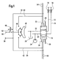
- the electro-hydraulic circuit shown in Fig. 1 is on a work vehicle, especially a telescopic loader, arranged. It contains an electromagnetically operated hydraulic control valve 10, which 4 ways and 3 positions having.
- the two right ways of the control valve 10 are via a hydraulic line 12, 14 with a quick coupling 16, 18 in connection.
- the circuit can be combined with hydraulic components connect the implement that can be coupled to the work vehicle in order to to supply the components with hydraulic fluid and the perform the desired work functions.
- the two right ways of the control valve 10 are on the one hand with a pressure channel 20 and the other with a return channel 22 in connection.
- the pressure channel 20 is part of the vehicle hydraulic supply system, by a hydraulic pump 24 is fed.
- the return channel 22 is at one Storage container 26 connected, which is usually depressurized is.
- control valve spool If the control valve spool is moved down, so it connects the return duct 22 with the left one Quick coupling 18 and the pressure channel 20 with the right Quick coupling 16. On the other hand, the control valve spool is off shifted upwards from its middle position, so connects the control valve 10 the return channel 22 with the right Quick coupling 16 and the pressure channel 20 with the left Quick coupling 18.
- the control valve spool is controlled by two centering springs 28, 30 pushed into its middle position. Divided by two electromagnetic actuators 32, 34 can be Control valve spool against the force of the centering springs 28, 30 move to either the up or down position.
- On first electrical connection of the actuators 30, 32 is via electrical connecting lines 34, 36 to a first Pol 38 of a vehicle battery not shown in Connection.
- a second electrical connection each Actuator 30, 32 is via an associated electrical line 40, 42 with a manually operated rocker switch 44 connected, the one spring-centered rest position and two Has deflection positions.
- the center tap 46 of the rocker switch 44 is via a relay 48 connected to a second pole 50 of the vehicle battery.
- the Relay 48 is in the ignition circuit of the Vehicle integrated so that its contact point 52 only is then closed when the ignition switch is in Ignition position is.
- rocker switch 44 The two remain in the rest position of the rocker switch 44 second electrical connections of the actuators 32, 44 free, so that no electrical circuit is closed and on the Control valve spool no forces are exerted on this push out of its shown middle closed position.
- the rocker switch 44 is operated by hand and in one of its brought two deflection positions, so connects Rocker switch 44 with closed contact point 52 of the relay 48 the second pole 50 via the corresponding electrical Line 40 or 42 with one of the actuators 32, 34, which move the control valve spool up or down, so that pressure equalization between the quick couplings 16, 18 and the pressure channel 20 and the return channel 22 becomes.
- the circuit shown is only functional when contact point 52 of relay 48 is closed, whereby the second pole 50 with the center tap 46 of the rocker switch 44 connected is. This is only the case when the ignition switch is in its ignition position.
- the quick couplings 16, 18 with the Connect hydraulic circuit of an attachment or from this can separate the to the quick couplings 16, 18th leading hydraulic lines 12, 14 are depressurized.
- the operator brings the ignition switch to the Work vehicle in its ignition position, but without the Start vehicle engine. In this position the Hydraulic pump 24 is not driven and sets the pressure channel 20 not under hydraulic pressure.
- the operator now brings the Rocker switch 44, for example, in its upper deflection position, so that he has the electrical lead 40 with the second pole 50 connects and excites the upper actuator 32, which the Brings the control valve spool to the upper position. In this Position is the left quick connector 18 with the unpressurized Return channel 22 connected and relieved of pressure so that they are can be solved.
- the actuators 32, 34 of the control valve 10 In addition to the integration in the circuit shown can the actuators 32, 34 of the control valve 10 also the operational control of the inflow and outflow of the Hydraulic fluid flowing through the quick connectors Attachment is headed, serve.
- the Actuators 32, 34 electrical control lines 54, 56 connected with an appropriate, not closer control circuit shown are connected.
- the operational Control of the control valve 10 can, for example, by a Joystick arranged in the vehicle cabin.
- FIG. 2 shows the side view of a telescopic arm 60, is the part of a telescopic loader, not shown. in the there is a front area of the telescopic arm 60 Attachment interface, which is a hydraulically operated Fork 62 trained attachment is attached. About an in Fig. 2 not visible control valve 10, two Hydraulic lines 12, 14 and two quick couplings 16, 18 is the fork 62 to the hydraulic circuit of the telehandler connected. In the front area of the telescopic arm 60, in the The rocker switch 44 is mounted near the mounting interface. This spatial proximity makes it easier for the operator Assembly and disassembly of the attachment because they are on site Pressure relief of the quick couplings 16, 18 can make and does not have to climb into the vehicle cabin first.
Landscapes
- Engineering & Computer Science (AREA)
- General Engineering & Computer Science (AREA)
- Mechanical Engineering (AREA)
- Mining & Mineral Resources (AREA)
- Civil Engineering (AREA)
- Structural Engineering (AREA)
- Chemical & Material Sciences (AREA)
- Analytical Chemistry (AREA)
- Physics & Mathematics (AREA)
- Fluid Mechanics (AREA)
- Operation Control Of Excavators (AREA)
- Fluid-Pressure Circuits (AREA)
Abstract
Description
- Fig. 1
- einen erfindungsgemäßen elektro-hydraulischen Schaltungskreis und
- Fig. 2
- den Teleskoparm eines Teleskopladers, der einen erfindungsgemäßen Schaltungskreis enthält.
Claims (10)
- Elektro-hydraulischer Schaltungskreis zur Druckentlastung eines Schnellkupplungskreises mit wenigstens zwei hydraulischen Schnellkupplungen (16, 18), durch welche hydraulische Komponenten eines Anbaugerätes (62) mit dem Hydraulikversorgungskreis eines Arbeitsfahrzeugs lösbar verbindbar sind, wobei die Schnellkupplungen (16, 18) über Hydraulikleitungen (12, 14) unter Zwischenschaltung wenigstens eines elektromagnetisch ansteuerbaren Steuerventils (10) wahlweise mit einem fahrzeugseitigen Druckkanal (20) oder mit einem fahrzeugseitigen Rücklaufkanal (22) verbindbar sind, dadurch gekennzeichnet, dass wenigstens ein von Hand betätigbarer, elektrischer Druckentlastungsschalter (44) vorgesehen ist, der mit einer Spannungsquelle und dem wenigstens einen Steuerventil (10) derart in Verbindung steht, dass bei einer Schalterbetätigung das Steuerventil (10) aus einer Sperrstellung in eine Durchflussstellung, in der wenigstens eine Schnellkupplungen (16, 18) mit dem Rücklaufkanal (22) verbunden wird, umschaltet.
- Schaltungskreis nach Anspruch 1, dadurch gekennzeichnet, dass der Druckentlastungsschalter ein Wippschalter (44) ist, der aus einer Ruhestellung in wenigstens zwei unterschiedliche Wippstellungen auslenkbar ist, um wahlweise eine der Schnellkupplungen (16, 18) mit dem Rücklaufkanal (22) zu verbinden.
- Schaltungskreis nach Anspruch 1 oder 2, dadurch gekennzeichnet, dass das Steuerventil (10) zwischen wenigstens drei Stellungen bewegbar ist, wobei in einer ersten Stellung, eine erste Schnellkupplung (16, 18) mit dem Rückflusskanal (22) verbunden wird, eine zweite Stellung eine Sperrstellung ist und in einer dritten Stellung eine zweite Schnellkupplung (16, 18) mit dem Rückflusskanal (22) verbunden wird.
- Schaltungskreis nach Anspruch 3, dadurch gekennzeichnet, dass zusätzlich in der ersten Stellung des Steuerventils (10) die zweite Schnellkupplung (16, 18) mit dem Druckkanal (20) verbunden wird und in der dritten Stellung des Steuerventils (10) die erste Schnellkupplung (16, 18) mit dem Druckkanal (20) verbunden wird.
- Schaltungskreis nach einem der Ansprüche 1 bis 4, dadurch gekennzeichnet, dass das Steuerventil (10) in einen elektrischen Steuerkreis zur betriebsmäßigen Steuerung des Zuflusses und Abflusses der Hydraulikflüssigkeit zu dem Anbaugerät (62) eingebunden ist.
- Schaltungskreis nach einem der Ansprüche 1 bis 5, dadurch gekennzeichnet, dass Mittel (48, 52) vorgesehen sind, durch die der elektrische Kreis mit Druckentlastungsschalter (44) und Steuerventil (10) nur dann mit der Spannungsquelle verbunden ist, wenn das Zündschloss des Arbeitsfahrzeugs auf Zündstellung steht.
- Schaltungskreislauf nach einem der Ansprüche 1 bis 6, dadurch gekennzeichnet, dass der Druckentlastungsschalter (44) in der Nähe des Anbaugerätes (62) außen am Fahrzeug montierbar ist.
- Arbeitsfahrzeug mit einem Schaltungskreis nach einem der Ansprüche 1 bis 7.
- Teleskoplader mit einem Schaltungskreis nach einem der Ansprüche 1 bis 7.
- Teleskoplader nach Anspruch 9, dadurch gekennzeichnet, dass der Druckentlastungsschalter (44) in einem seitlichen, vorderen Bereich an dem Teleskoparm (60) montierbar ist.
Applications Claiming Priority (2)
| Application Number | Priority Date | Filing Date | Title |
|---|---|---|---|
| DE2001111632 DE10111632A1 (de) | 2001-03-10 | 2001-03-10 | Elektro-hydraulischer Schaltungskreis zur Druckentlastung von Schnellkupplungen |
| DE10111632 | 2001-03-10 |
Publications (3)
| Publication Number | Publication Date |
|---|---|
| EP1239208A2 true EP1239208A2 (de) | 2002-09-11 |
| EP1239208A3 EP1239208A3 (de) | 2004-01-14 |
| EP1239208B1 EP1239208B1 (de) | 2005-12-14 |
Family
ID=7677035
Family Applications (1)
| Application Number | Title | Priority Date | Filing Date |
|---|---|---|---|
| EP20020004830 Expired - Lifetime EP1239208B1 (de) | 2001-03-10 | 2002-03-02 | Elektro-hydraulischer Schaltungskreis zur Druckentlastung von Schnellkupplungen |
Country Status (2)
| Country | Link |
|---|---|
| EP (1) | EP1239208B1 (de) |
| DE (2) | DE10111632A1 (de) |
Cited By (2)
| Publication number | Priority date | Publication date | Assignee | Title |
|---|---|---|---|---|
| WO2008132874A1 (ja) | 2007-04-19 | 2008-11-06 | Caterpillar Japan Ltd. | 作業機械の制御装置 |
| WO2022073651A1 (en) * | 2020-10-06 | 2022-04-14 | Caterpillar Work Tools B.V. | Automatic pressure release |
Families Citing this family (2)
| Publication number | Priority date | Publication date | Assignee | Title |
|---|---|---|---|---|
| DE102012012299A1 (de) * | 2012-04-05 | 2013-10-10 | Atlas Copco Construction Tools Gmbh | Hydraulisches Anbaugerät |
| DE102020103320A1 (de) | 2020-02-10 | 2021-08-12 | Kramer-Werke Gmbh | Mobile Arbeitsmaschine mit einer Werkzeughaltevorrichtung zum Halten eines Arbeitswerkzeugs |
Family Cites Families (6)
| Publication number | Priority date | Publication date | Assignee | Title |
|---|---|---|---|---|
| GB8625778D0 (en) * | 1986-10-28 | 1986-12-03 | Knackstedt J S | Connector |
| DE9003178U1 (de) * | 1990-03-19 | 1990-08-09 | O & K Orenstein & Koppel Ag, 1000 Berlin | Radlader |
| DE4210790A1 (de) * | 1991-04-04 | 1992-10-08 | Orenstein & Koppel Ag | Arbeitsmaschine, insbesondere baumaschine |
| ATE130919T1 (de) * | 1991-07-09 | 1995-12-15 | Faster Srl | Schnellkupplung zum jeweils gleichzeitigen herstellen oder lösen der verbindungen mehrerer kupplungen und/oder anschlussstecker, insbesondere kupplungsblock für anbaufrontlader an fahrzeugen. |
| SE510139C3 (sv) * | 1996-02-23 | 1999-05-25 | Thure Ekman | Hopkopplingsanordning vid en mobil foersta enhet och en till denna hopkopplingsbar andra enhet |
| DE19615893C1 (de) * | 1996-04-22 | 1997-06-05 | Case Germany Gmbh | Vorrichtung zum Sammeln und Ablassen von Fluiden an vertikal übereinander angeordneten Schnellkupplungen |
-
2001
- 2001-03-10 DE DE2001111632 patent/DE10111632A1/de not_active Withdrawn
-
2002
- 2002-03-02 EP EP20020004830 patent/EP1239208B1/de not_active Expired - Lifetime
- 2002-03-02 DE DE50205239T patent/DE50205239D1/de not_active Expired - Lifetime
Cited By (5)
| Publication number | Priority date | Publication date | Assignee | Title |
|---|---|---|---|---|
| WO2008132874A1 (ja) | 2007-04-19 | 2008-11-06 | Caterpillar Japan Ltd. | 作業機械の制御装置 |
| EP2138639A4 (de) * | 2007-04-19 | 2011-04-20 | Caterpillar Sarl | Steuereinheit für eine arbeitsmaschine |
| WO2022073651A1 (en) * | 2020-10-06 | 2022-04-14 | Caterpillar Work Tools B.V. | Automatic pressure release |
| CN116324188A (zh) * | 2020-10-06 | 2023-06-23 | 卡特彼勒作业机具有限公司 | 自动压力释放 |
| US12601149B2 (en) | 2020-10-06 | 2026-04-14 | Caterpillar Work Tools B.V. | Automatic pressure release |
Also Published As
| Publication number | Publication date |
|---|---|
| EP1239208A3 (de) | 2004-01-14 |
| DE10111632A1 (de) | 2002-09-19 |
| DE50205239D1 (de) | 2006-01-19 |
| EP1239208B1 (de) | 2005-12-14 |
Similar Documents
| Publication | Publication Date | Title |
|---|---|---|
| DE102004050294B3 (de) | Hydraulische Ventilanordnung | |
| EP0605851A1 (de) | Lageregelung für ein an einen Schlepper anhängbares Gerät | |
| DE2758268A1 (de) | Vorrichtung zum antrieb mehrerer druckmittelbetaetigter motoren | |
| DE102008023068A1 (de) | Steuerung für angebaute, gezogene oder aufgesattelte Landmaschinen, als ausechselbare Ausrüstung in Verbindung mit Traktoren | |
| EP0230256A2 (de) | Bedienungsgestänge mit Schalthebeln | |
| DE60208271T2 (de) | Hydraulisches System für ein Nutzfahrzeug | |
| DE3438353C2 (de) | ||
| EP0277602A2 (de) | Hydraulikanlage zur Betätigung von Arbeitsgeräten an Fahrzeugen | |
| EP1239208B1 (de) | Elektro-hydraulischer Schaltungskreis zur Druckentlastung von Schnellkupplungen | |
| DE10310314A1 (de) | Antriebsanordnung, insbesondere Hebevorrichtung eines Arbeitsfahrzeugs | |
| DE68912013T2 (de) | Elektrisch steuerbares hydraulisches Hilfssystem für Radlader. | |
| DE2937764A1 (de) | Hydraulisches system | |
| DE2751449B1 (de) | Vorrichtung zur Lage- und/oder Arbeitstiefenregelung an landwirtschaftlichen Maschinen,insbesondere fuer mit Ackerschleppern gekuppelte Anbaugeraete | |
| DE69003414T2 (de) | Hydraulischer Kreis zum Gebrauch in Hebemechanismen bei Arbeitsfahrzeugen. | |
| DE60306847T2 (de) | Pflugwendevorrichtung | |
| EP2541071B1 (de) | Ventilanordnung für ein hydraulisches Steuerungssystem | |
| DE102021212356A1 (de) | Arbeitsmaschine mit einem radialen und vertikalen hubweg mit einem gemeinsamen auslegerbaugruppendrehpunkt | |
| DE60201552T2 (de) | Ventil zum Ermöglichen der Kontrolle eines fluidbetätigten Aktuators | |
| DE2025114A1 (de) | Strömungsmittelgerät, insbesondere zum Betätigen von Ventilen, Schaltern, Motoren und ähnlichem | |
| DE69935293T2 (de) | Steuervorrichtung für eine Erdbewegungsmaschine | |
| DE1780079C2 (de) | Lenkvorrichtung für Landmaschinen, insbesondere selbstfahrende Mähdrescher | |
| EP1111247B1 (de) | Arbeitshydrauliksystem mit zwei Pumpen | |
| EP4711629A1 (de) | Anordnung zum betreiben eines hydraulischen steuerventils für einen landwirtschaftlichen traktor | |
| EP1982572A1 (de) | Antriebsaggregat für gärtnerische oder landwirtschaftliche Arbeitsgeräte | |
| DE2259003C3 (de) | Sicherheitsvorrichtung für landwirtschaftliche Maschinen mit hydraulisch höhenverstellbarer Arbeitsplattform |
Legal Events
| Date | Code | Title | Description |
|---|---|---|---|
| PUAI | Public reference made under article 153(3) epc to a published international application that has entered the european phase |
Free format text: ORIGINAL CODE: 0009012 |
|
| AK | Designated contracting states |
Kind code of ref document: A2 Designated state(s): AT BE CH CY DE DK ES FI FR GB GR IE IT LI LU MC NL PT SE TR |
|
| AX | Request for extension of the european patent |
Free format text: AL;LT;LV;MK;RO;SI |
|
| PUAL | Search report despatched |
Free format text: ORIGINAL CODE: 0009013 |
|
| AK | Designated contracting states |
Kind code of ref document: A3 Designated state(s): AT BE CH CY DE DK ES FI FR GB GR IE IT LI LU MC NL PT SE TR |
|
| AX | Request for extension of the european patent |
Extension state: AL LT LV MK RO SI |
|
| RIC1 | Information provided on ipc code assigned before grant |
Ipc: 7F 15B 21/04 B Ipc: 7F 16L 37/00 A Ipc: 7E 02F 9/22 B Ipc: 7E 02F 3/36 B |
|
| 17P | Request for examination filed |
Effective date: 20040714 |
|
| AKX | Designation fees paid |
Designated state(s): DE FR GB |
|
| 17Q | First examination report despatched |
Effective date: 20040922 |
|
| GRAP | Despatch of communication of intention to grant a patent |
Free format text: ORIGINAL CODE: EPIDOSNIGR1 |
|
| GRAS | Grant fee paid |
Free format text: ORIGINAL CODE: EPIDOSNIGR3 |
|
| GRAA | (expected) grant |
Free format text: ORIGINAL CODE: 0009210 |
|
| AK | Designated contracting states |
Kind code of ref document: B1 Designated state(s): DE FR GB |
|
| REG | Reference to a national code |
Ref country code: GB Ref legal event code: FG4D Free format text: NOT ENGLISH |
|
| REF | Corresponds to: |
Ref document number: 50205239 Country of ref document: DE Date of ref document: 20060119 Kind code of ref document: P |
|
| GBT | Gb: translation of ep patent filed (gb section 77(6)(a)/1977) |
Effective date: 20060108 |
|
| ET | Fr: translation filed | ||
| PLBE | No opposition filed within time limit |
Free format text: ORIGINAL CODE: 0009261 |
|
| STAA | Information on the status of an ep patent application or granted ep patent |
Free format text: STATUS: NO OPPOSITION FILED WITHIN TIME LIMIT |
|
| 26N | No opposition filed |
Effective date: 20060915 |
|
| REG | Reference to a national code |
Ref country code: FR Ref legal event code: PLFP Year of fee payment: 15 |
|
| PGFP | Annual fee paid to national office [announced via postgrant information from national office to epo] |
Ref country code: DE Payment date: 20160219 Year of fee payment: 15 |
|
| PGFP | Annual fee paid to national office [announced via postgrant information from national office to epo] |
Ref country code: GB Payment date: 20160329 Year of fee payment: 15 Ref country code: FR Payment date: 20160328 Year of fee payment: 15 |
|
| REG | Reference to a national code |
Ref country code: DE Ref legal event code: R119 Ref document number: 50205239 Country of ref document: DE |
|
| GBPC | Gb: european patent ceased through non-payment of renewal fee |
Effective date: 20170302 |
|
| REG | Reference to a national code |
Ref country code: FR Ref legal event code: ST Effective date: 20171130 |
|
| PG25 | Lapsed in a contracting state [announced via postgrant information from national office to epo] |
Ref country code: DE Free format text: LAPSE BECAUSE OF NON-PAYMENT OF DUE FEES Effective date: 20171003 Ref country code: FR Free format text: LAPSE BECAUSE OF NON-PAYMENT OF DUE FEES Effective date: 20170331 |
|
| PG25 | Lapsed in a contracting state [announced via postgrant information from national office to epo] |
Ref country code: GB Free format text: LAPSE BECAUSE OF NON-PAYMENT OF DUE FEES Effective date: 20170302 |