EP1238930A2 - Bogentrennvorrichtung - Google Patents
Bogentrennvorrichtung Download PDFInfo
- Publication number
- EP1238930A2 EP1238930A2 EP01130249A EP01130249A EP1238930A2 EP 1238930 A2 EP1238930 A2 EP 1238930A2 EP 01130249 A EP01130249 A EP 01130249A EP 01130249 A EP01130249 A EP 01130249A EP 1238930 A2 EP1238930 A2 EP 1238930A2
- Authority
- EP
- European Patent Office
- Prior art keywords
- suction
- suction tube
- vacuum device
- vacuum
- stack
- Prior art date
- Legal status (The legal status is an assumption and is not a legal conclusion. Google has not performed a legal analysis and makes no representation as to the accuracy of the status listed.)
- Granted
Links
- 238000000034 method Methods 0.000 claims description 10
- 239000000047 product Substances 0.000 description 23
- 238000007789 sealing Methods 0.000 description 4
- 238000000926 separation method Methods 0.000 description 2
- 241000252169 Catostomus commersonii Species 0.000 description 1
- 241000124008 Mammalia Species 0.000 description 1
- 238000005553 drilling Methods 0.000 description 1
- 230000000694 effects Effects 0.000 description 1
- 238000009413 insulation Methods 0.000 description 1
- 238000004519 manufacturing process Methods 0.000 description 1
- 238000009751 slip forming Methods 0.000 description 1
- 239000013589 supplement Substances 0.000 description 1
- 230000001360 synchronised effect Effects 0.000 description 1
Images



Classifications
-
- B—PERFORMING OPERATIONS; TRANSPORTING
- B65—CONVEYING; PACKING; STORING; HANDLING THIN OR FILAMENTARY MATERIAL
- B65H—HANDLING THIN OR FILAMENTARY MATERIAL, e.g. SHEETS, WEBS, CABLES
- B65H3/00—Separating articles from piles
- B65H3/08—Separating articles from piles using pneumatic force
- B65H3/0808—Suction grippers
- B65H3/085—Suction grippers separating from the bottom of pile
- B65H3/0858—Suction grippers separating from the bottom of pile this action resulting merely in a curvature of each article being separated
-
- B—PERFORMING OPERATIONS; TRANSPORTING
- B65—CONVEYING; PACKING; STORING; HANDLING THIN OR FILAMENTARY MATERIAL
- B65H—HANDLING THIN OR FILAMENTARY MATERIAL, e.g. SHEETS, WEBS, CABLES
- B65H2406/00—Means using fluid
- B65H2406/30—Suction means
- B65H2406/34—Suction grippers
- B65H2406/341—Suction grippers being oscillated in arcuate paths
-
- B—PERFORMING OPERATIONS; TRANSPORTING
- B65—CONVEYING; PACKING; STORING; HANDLING THIN OR FILAMENTARY MATERIAL
- B65H—HANDLING THIN OR FILAMENTARY MATERIAL, e.g. SHEETS, WEBS, CABLES
- B65H2511/00—Dimensions; Position; Numbers; Identification; Occurrences
- B65H2511/20—Location in space
Definitions
- the present invention relates to a device for separating flat products from a stack of flat products according to the preamble of claim 1.
- Such a sheet separator is e.g. known from US 3,988,016.
- This font describes a high speed paper loading device for loading Inserts in newspapers.
- the supplements are arranged so that they form a stack and a vacuum gripping element grips the lowest insert to be inserted from the stack and carries it to a pair of rollers, which passes the insert on to an open newspaper.
- there sheets of different types and thickness require different treatment e.g. with regard to stroke or suction force to be applied. So a thin one requires Sheet another suction stroke than an insert of 120 pages.
- the different Suction element movement requirements result from the way in which the sheets or Sub-products must be arranged and controlled for correct separation.
- the bottom of the stack is lifted up with heavy sections to rule out that more sheets are accidentally pulled off than desired.
- The is achieved by repositioning the lifting hook and the retaining elements become. If these settings are made, the Vacuum cup movement can be changed.
- To an upward To achieve suction element movement so that it must correctly attack the stack Cover the squeegee over a larger angular range.
- US Pat. No. 6,168,148 describes an adjustable suction device that has an upper one and lower part, which is coupled to a central lever.
- the central lever is rotatable about an axis extending through the central lever.
- the setting can by moving the axis along the central lever.
- the suction mechanism can be in relation to the stack of flat products be pivoted so that the suction cup can be moved so that it is a bottom attacks flat product from the stack of flat products.
- the vacuum device may have a bore, the second end of the Suction tube is slidably received in the bore.
- the suction mechanism can have a slide for positioning the suction tube, the slider being coupled to the first end of the suction tube and sliding in the Relation to the vacuum device is arranged.
- the slide can be slidably arranged on the vacuum device.
- a Fastening device can be used to hold the slide in a predetermined position be provided.
- the fastening device can comprise a screw.
- the vacuum device can have a vacuum inlet opening for generating a vacuum in the vacuum device.
- a suction bar can be provided, with the vacuum device on the suction bar arranged.
- the suction mechanism can be a slider for positioning the suction tube and the second suction tube, the slider to the first end of the suction tube and the first end of the second suction tube is coupled and slidable in relation to the Vacuum device is arranged.
- the slide can be slidably arranged on the vacuum device.
- the device according to the invention and the method according to the invention make this possible individual adjustment of the suction cups or their adjustment in groups to the stroke of the of the respective vacuum cleaner according to the respective flat product that is manufactured by the stack is separated in a feed magazine.
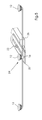
- Fig. 1 shows a schematic side view of an inventive Sheet separator.
- a stack of flat products 10, in particular sheets or Signatures made of paper or plastic are arranged in a magazine 13 and lie flat on a signature table 14 against a front guide element 15.
- One or more Lifting hooks and / or restraint devices can be provided to when supporting the stack 10 and separating products from the stack 10 help.
- a gap or a recess 17 is provided at the lower end of the stack 10.
- the suction cup 24 rotatable about a pivot point 32 of the suction cup (Fig. 3) and can be turned in the direction indicated by arrow B to move upwards and to attack the bottom arc 18 and then down to the bottom arc 18 to remove from the stack 10.
- Suction cup 24 includes a suction cup that is coupled to a suction tube 16 at a first end of suction tube 16.
- the suction tube 16 extends through the slide 20.
- the slide 20 can be moved in the horizontal direction by loosening the locking screw 22. By moving the slide 20, it is possible to adjust the position of the suction cup 12, as indicated in FIG. 1 by the distance a 1 , to a different distance, indicated in FIG. 2 as the distance a 2 .
- the suction tube 16 is coupled at its second end to a vacuum device 26 and movably disposed in the bore 27 of the vacuum device 26 to allow positioning of the suction cup 12 when the slider 20 is moved by the pivot radius r of the suction cup in relation to the pivot point 32 to change.
- the position of the suction cup 12 can be adjusted so that it creates a suction stroke or swivel angle that is adapted to the respective type of flat products in the stack 10 and the corresponding lifting hook and restrictor positions.
- the sealing device 28 is thus within the vacuum device 26 on the suction tube 16 coupled that the suction tube can still be moved while the suction tube a vacuum can be assigned.
- the vacuum inlet opening 30 is in the Vacuum device provided so that a vacuum can be created.
- the suction cup 12 can be a flexible cup-shaped element or another element, that is suitable for gripping the bottom sheet 18 using a vacuum suction element.
- Suction tube 16 is preferably a rigid tube with a circular cross-section or another suitable pipeline for connection to the suction cup 12 one end and with the vacuum device 26 at the other end while in the Relative to the vacuum device 26 is movable to the position of the suction cup 12 to change.
- the slider 20 may be a thin, flat, elongated member with a Be opening so that the suction tube 16 can be connected to the suction cup 12.
- the slider 20 can be used in other embodiments according to the invention grasp or hold the suction tube 16 and / or the suction cup 12 in a suitable manner.
- the Slider 20 can define a slot that receives the set screw 22 so the slide 20 can move in relation to the locking screw and thereby the Reposition the suction tube 16 with the suction cup 12.
- the locking screw 22 can screwed directly into the vacuum device 26 or extend into it. Further Configurations that slidably reset the suction tube 16 and the suction cup 12 and the subsequent determination in relation to the vacuum device 26 enable are also conceivable.
- Vacuum device 26 is preferably a rigid body with one formed therein Bore 27.
- the bore 27 may have a circular cross-section or another slidably receiving the suction tube 16 have a suitable shape to a suction effect to allow via the suction tube to the suction cup.
- the sealing device 28 serves as Insulation of the inside of the vacuum device 26 against pressure from the atmosphere, while the suction tube is still sliding relative to the vacuum device 26 can.
- the seal 28 can be a rubber ring or other suitable sealing element his.
- the vacuum inlet opening 30 can be with a vacuum pump or another suitable device for forming a vacuum in the vacuum device 26 be connected.
- the vacuum can be continuously formed in the vacuum device 26 or at time intervals that relate to the removal of the sheets 18 from the stack 10 are synchronized.
- Vacuum device 26 may be attached to squeegee 35 or in a variety of other suitable configurations so that the vacuum device is pivoted to bring the suction cup 12 to the bottom sheet 18 of the stack 10.
- some embodiments of the present invention can do a variety of suction cups 24, each of which has an associated vacuum device 26, a suction tube 16, a suction cup 12 and a slide 20.
- vacuum devices 26 can be attached to the suction bar 35, so that all suction elements are pivoted at the pivot point 32 and in line be moved to take the bottom sheet 18.
- Each of the sliders 20 can be adjusted independently to adjust the respective position of each suction cup 12.
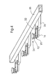
- FIG 5 shows that in some embodiments according to the invention more than one suction cup 12 are coupled to the suction tube 16. The position of all suction cups 12 attached to the Suction tube 16 are coupled at once by the slider 20 as above described is moved.
- FIG. 6 shows that in some embodiments according to the invention there are more than one Suction tube 16, each coupled to a respective suction cup, by the slider 20 can extend.
- the slide 20 can e.g. a transverse one Have extension 21 through which the suction tubes 16 extend.
- the Suction tubes 16 can e.g. to an associated suction device 26 of the previous described type can be coupled.
- the Invention more than one suction cup 12 can be coupled to each suction tube 16, which passes through a single slide 20 extends.
Landscapes
- Engineering & Computer Science (AREA)
- Mechanical Engineering (AREA)
- Sheets, Magazines, And Separation Thereof (AREA)
- Manufacturing Of Electric Cables (AREA)
- Insulated Conductors (AREA)
- Magnetic Resonance Imaging Apparatus (AREA)
Abstract
Description
- Fig. 1
- eine schematische Seitenansicht einer erfindungsgemäßen Vorrichtung in einer ersten Einstellposition,
- Fig. 2
- eine schematische Seitenansicht einer erfindungsgemäßen Vorrichtung in einer zweiten Einstellposition,
- Fig. 3
- eine erfindungsgemäße Vorrichtung mit einem Sauger in einer gedrehten Position,
- Fig. 4
- eine perspektivische Ansicht einer erfindungsgemäßen Vorrichtung mit einer Vielzahl von Saugern,
- Fig. 5
- eine perspektivische Ansicht einer erfindungsgemäßen Vorrichtung mit einer Vielzahl von Saugern, die an eine Saugröhre gekoppelt sind, und
- Fig. 6
- eine perspektivische Ansicht einer erfindungsgemäßen Vorrichtung mit einer Vielzahl von Saugröhren, die sich durch einen Schieber erstrecken.
- 10
- Stapel aus flachen Produkten
- 12
- Saugnapf
- 13
- Magazin
- 14
- Signaturentisch
- 15
- Frontführungselement
- 16
- Saugröhre
- 17
- Spalt / Ausnehmung
- 18
- unterster Bogen
- 20
- Schieber
- 21
- querverlaufende Verlängerung
- 22
- Feststellschraube
- 24
- Sauger
- 26
- Vakuumvorrichtung
- 27
- Bohrung
- 28
- Abdichtungsvorrichtung
- 30
- Vakuumeintrittsöffnung
- 32
- Schwenkpunkt des Saugers
- 35
- Saugleiste
- a1, a2
- Entfernung
- B
- Pfeil
Claims (15)
- Vorrichtung zum Trennen flacher Produkte von einem Stapel (10) aus flachen Produkten, wobei die Vorrichtung einen Saugmechanismus mit folgenden Elementen umfasst:dadurch gekennzeichnet, dass das zweite Ende der Saugröhre (16) bewegbar in der Vakuumvorrichtung (26) aufgenommen ist, so dass der mindestens eine Saugnapf (12) relativ zu dem Stapel (10) aus flachen Produkten veränderbar positionierbar ist.einer Saugröhre (16) mit einem ersten und einem zweiten Ende;mindestens einem Saugnapf (12), der an dem ersten Ende der Saugröhre (16) an die Saugröhre (16) gekoppelt ist; undeiner Vakuumvorrichtung (26) zum Schaffen eines Vakuums, wobei die Vakuumvorrichtung (26) an dem zweiten Ende der Saugröhre (16) an die Saugröhre (16) gekoppelt ist;
- Vorrichtung nach Anspruch 1,
dadurch gekennzeichnet, dass der Saugmechanismus im Verhältnis zu dem Stapel (10) aus flachen Produkten schwenkbar ist, damit der mindestens ein Saugnapf (12) bewegt werden kann, um das unterste flache Produkt von dem Stapel (10) aus flachen Produkten anzugreifen. - Vorrichtung nach Anspruch 1,
dadurch gekennzeichnet, dass die Vakuumvorrichtung (26) eine Bohrung (27) aufweist, wobei das zweite Ende der Saugröhre (16) gleitend in der Bohrung (27) angeordnet ist. - Vorrichtung nach Anspruch 1,
dadurch gekennzeichnet, dass der Saugmechanismus des Weiteren einen Schieber (20) zum Positionieren der Saugröhre (16) umfasst, wobei der Schieber (20) an das erste Ende der Saugröhre (16) gekoppelt ist und gleitend im Verhältnis zu der Vakuumvorrichtung (26) angeordnet ist. - Vorrichtung nach Anspruch 4,
dadurch gekennzeichnet, dass der Schieber (20) gleitend auf der Vakuumvorrichtung (26) angeordnet ist. - Vorrichtung nach Anspruch 4,
dadurch gekennzeichnet, dass der Saugmechanismus des Weiteren eine Befestigungsvorrichtung zum Halten des Schiebers (20) in einer vorbestimmten Position umfasst. - Vorrichtung nach Anspruch 1,
dadurch gekennzeichnet, dass die Vorrichtung des Weiteren eine Saugleiste (35) umfasst, wobei die Vakuumvorrichtung (26) auf der Saugleiste (35) angeordnet ist. - Vorrichtung nach Anspruch 1,
dadurch gekennzeichnet, dass eine zweite Saugröhre (16) mit einem ersten und einem zweiten Ende,
ein zweiter mindestens einer Saugnapf (12), der an dem ersten Ende der zweiten Saugröhre (16) an die zweite Saugröhre (16) gekoppelt ist, und eine zweite Vakuumvorrichtung (26) zum Schaffen eines Vakuums vorgesehen sind, wobei die zweite Vakuumvorrichtung (26) an dem zweiten Ende der Saugröhre (16) an die Saugröhre (16) gekoppelt ist. - Vorrichtung nach Anspruch 8,
dadurch gekennzeichnet, dass das jeweilige zweite Ende der zweiten Saugröhre (16) bewegbar in der zweiten Vakuumvorrichtung (26) angeordnet ist, damit der zweite mindestens eine Saugnapf (12) im Verhältnis zu dem Stapel (10) aus flachen Produkten unabhängig von dem mindestens einen Saugnapf (12) veränderbar positioniert ist. - Vorrichtung nach Anspruch 9,
dadurch gekennzeichnet, dass der Saugmechanismus des Weiteren einen Schieber (20) zum Positionieren der Saugröhre (16) und der zweiten Saugröhre (16) umfasst, wobei der Schieber (20) an das erste Ende der Saugröhre (16) und an das erste Ende der zweiten Saugröhre (16) gekoppelt ist und gleitend im Verhältnis zu der Vakuumvorrichtung (26) angeordnet ist. - Vorrichtung nach Anspruch 10,
dadurch gekennzeichnet, dass der Schieber (20) gleitend auf der Vakuumvorrichtung (26) angeordnet ist. - Verfahren zum Trennen von flachen Produkten von einem Stapel (10) aus flachen Produkten, wobei das Verfahren die folgenden Verfahrensschritte umfasst:Bereitstellen eines Saugmechanismus mit einer Saugröhre (16) mit einem ersten und einem zweiten Ende, einem mindestens einem Saugnapf (12), der an dem ersten Ende der Saugröhre (16) an die Saugröhre (16) gekoppelt ist, einer Vakuumvorrichtung (26) zum Schaffen eines Vakuums, wobei die Vakuumvorrichtung (26) an dem zweiten Ende der Saugröhre an die Saugröhre gekoppelt ist, wobei die Saugröhre (16) bewegbar in der Vakuumvorrichtung (26) angeordnet ist; undVerändern einer Position des mindestens einen Saugnapfes (12) im Verhältnis zu dem Stapel (10) aus flachen Produkten durch Bewegen der Saugröhre (16) im Verhältnis zu der Vakuumvorrichtung (26).
- Verfahren nach Anspruch 12,
dadurch gekennzeichnet, dass der Saugmechanismus relativ zu dem Stapel (10) aus flachen Produkten geschwenkt wird, so dass der mindestens eine Saugnapf (12) bewegt wird, um ein unterstes flaches Produkt von einem Stapel (10) aus flachen Produkten anzugreifen. - Verfahren nach Anspruch 13,
dadurch gekennzeichnet, dass das Bewegen der Saugröhre (16) relativ zu der Vakuumvorrichtung (26) mittels eines Schiebers (20) zum Positionieren der Saugröhre (16) durchgeführt wird, wobei der Schieber (20) an das erste Ende der Saugröhre (16) gekoppelt ist und gleitend im Verhältnis zu der Vakuumvorrichtung (26) angeordnet ist. - Verfahren nach Anspruch 13, das des Weiteren die folgenden Verfahrensschritte umfasst:Bereitstellen einer zweiten Saugröhre (16) mit einem jeweiligen ersten und zweiten Ende, einem zweiten mindestens einen Saugnapf (12) der an dem ersten Ende der zweiten Saugröhre (16) an die zweite Saugröhre (16) gekoppelt ist und eine zweite Vakuumvorrichtung (26) zum Schaffen eines Vakuums, wobei die zweite Vakuumvorrichtung (26) an dem zweiten Ende der zweiten Saugröhre (16) an die zweite Saugröhre (16) gekoppelt ist; undÄndern einer Position des zweiten mindestens einen Saugnapfes (12) im Verhältnis zu dem Stapel (10) aus flachen Produkten durch Bewegen der zweiten Saugröhre (16) im Verhältnis zu der zweiten Vakuumvorrichtung (26).
Applications Claiming Priority (4)
| Application Number | Priority Date | Filing Date | Title |
|---|---|---|---|
| US26537701P | 2001-01-31 | 2001-01-31 | |
| US265377P | 2001-01-31 | ||
| US09/882,727 US6557845B2 (en) | 2001-01-31 | 2001-06-15 | Sheet separating device |
| US882727 | 2001-06-15 |
Publications (3)
| Publication Number | Publication Date |
|---|---|
| EP1238930A2 true EP1238930A2 (de) | 2002-09-11 |
| EP1238930A3 EP1238930A3 (de) | 2004-01-21 |
| EP1238930B1 EP1238930B1 (de) | 2006-05-10 |
Family
ID=26951164
Family Applications (1)
| Application Number | Title | Priority Date | Filing Date |
|---|---|---|---|
| EP01130249A Expired - Lifetime EP1238930B1 (de) | 2001-01-31 | 2001-12-19 | Bogentrennvorrichtung |
Country Status (4)
| Country | Link |
|---|---|
| US (1) | US6557845B2 (de) |
| EP (1) | EP1238930B1 (de) |
| AT (1) | ATE325762T1 (de) |
| DE (1) | DE50109753D1 (de) |
Families Citing this family (8)
| Publication number | Priority date | Publication date | Assignee | Title |
|---|---|---|---|---|
| JP4102540B2 (ja) * | 2000-10-25 | 2008-06-18 | 富士フイルム株式会社 | 板状部材の枚葉方法 |
| AUPR292501A0 (en) * | 2001-02-07 | 2001-03-01 | Silverbrook Research Pty. Ltd. | A method and apparatus (ART100) |
| US7080832B2 (en) * | 2003-05-14 | 2006-07-25 | Goss International Americas, Inc. | Sheet material feeder |
| US20070022714A1 (en) * | 2005-07-29 | 2007-02-01 | Flagg Michael F | Carton feeder with positionable vacuum cups |
| US20070138733A1 (en) * | 2005-12-16 | 2007-06-21 | Chris Gray | Pick mechanism |
| DE202006005312U1 (de) * | 2006-01-10 | 2006-06-01 | Wohlenberg Buchbindesysteme Gmbh | Vorrichtung zum Abkippen eines Teils einer zu vereinzelnden Signatur von einem Stapel |
| US7530209B2 (en) * | 2006-09-22 | 2009-05-12 | Philip Morris Usa Inc. | Coupon positioning and rotation wheel |
| DE102013018196A1 (de) * | 2013-10-30 | 2015-04-30 | Murrplastik Systemtechnik Gmbh | Vorrichtung zum Greifen und Transportieren eines Kennzeichnungsschildersatzes |
Citations (2)
| Publication number | Priority date | Publication date | Assignee | Title |
|---|---|---|---|---|
| US3988016A (en) | 1974-11-01 | 1976-10-26 | Cutler-Hammer, Inc. | High speed in-line paper inserting apparatus and method |
| US6168148B1 (en) | 1999-03-19 | 2001-01-02 | Heidelberger Druckmaschinen Ag | Sheet separating device |
Family Cites Families (8)
| Publication number | Priority date | Publication date | Assignee | Title |
|---|---|---|---|---|
| DE653260C (de) * | 1936-02-08 | 1937-11-19 | Brehmer Geb | Vorrichtung zum Absondern des obersten Bogens von einem Stapel |
| DE925410C (de) * | 1938-10-12 | 1955-03-21 | Georg Dr-Ing Spiess | Vorrichtung zum Abheben und Zufuehren des jeweils obersten Bogens eines Stapels in eine Bogen verarbeitende Maschine |
| DE1022238B (de) * | 1955-04-13 | 1958-01-09 | Georg Spiess Dr Ing | Vorrichtung zum Abheben und Zufuehren des jeweils obersten Bogens eines Stapels in eine Bogen verarbeitende Maschine, insbesondere Druck- und Falzmaschine |
| US4728092A (en) * | 1986-03-21 | 1988-03-01 | Astro Machine Corporation | Suction control system for suction cup sheet feeding apparatus |
| US5219432A (en) * | 1987-06-18 | 1993-06-15 | Compagnie Generale D'automatisme Cga Hgs | Device for unstacking flat objects |
| US5127207A (en) * | 1991-02-01 | 1992-07-07 | Cunningham Thomas J | Case blank feed device |
| JP2641642B2 (ja) * | 1991-05-24 | 1997-08-20 | 富士写真フイルム株式会社 | シート体供給装置 |
| DE10009666A1 (de) * | 1999-03-19 | 2000-09-21 | Heidelberger Druckmasch Ag | Verfahren zum Betrieb eines Hubsaugers und Hubsauger |
-
2001
- 2001-06-15 US US09/882,727 patent/US6557845B2/en not_active Expired - Fee Related
- 2001-12-19 AT AT01130249T patent/ATE325762T1/de not_active IP Right Cessation
- 2001-12-19 EP EP01130249A patent/EP1238930B1/de not_active Expired - Lifetime
- 2001-12-19 DE DE50109753T patent/DE50109753D1/de not_active Expired - Lifetime
Patent Citations (2)
| Publication number | Priority date | Publication date | Assignee | Title |
|---|---|---|---|---|
| US3988016A (en) | 1974-11-01 | 1976-10-26 | Cutler-Hammer, Inc. | High speed in-line paper inserting apparatus and method |
| US6168148B1 (en) | 1999-03-19 | 2001-01-02 | Heidelberger Druckmaschinen Ag | Sheet separating device |
Also Published As
| Publication number | Publication date |
|---|---|
| US6557845B2 (en) | 2003-05-06 |
| US20020101026A1 (en) | 2002-08-01 |
| ATE325762T1 (de) | 2006-06-15 |
| EP1238930A3 (de) | 2004-01-21 |
| EP1238930B1 (de) | 2006-05-10 |
| DE50109753D1 (de) | 2006-06-14 |
Similar Documents
| Publication | Publication Date | Title |
|---|---|---|
| DE69203432T2 (de) | Vorrichtung und Verfahren zum Transferieren von Gegenständen. | |
| DE19710236A1 (de) | Vorrichtung zum Bearbeiten von flachen, flexiblen Gegenständen, wie z. B. Karten aus Kunststoff oder Papier | |
| DE3706058C2 (de) | ||
| WO1995009796A1 (de) | Verfahren und vorrichtung zum bilden und versetzen von stapeln aus bedruckten blättern | |
| EP1429983B1 (de) | Vorrichtung zur ausrichtung von in einer lage übereinander angeordneten bogen | |
| EP1238930B1 (de) | Bogentrennvorrichtung | |
| EP1939008A2 (de) | Sammelhefter mit variabler Kettenteilung | |
| EP0179361A1 (de) | Vorrichtung zur Markierung von Druckbogenteilstapeln auf dem Ablagetisch einer Druckmaschine | |
| EP1394088A2 (de) | Vorrichtung zum Trennen von Vorfalz und Nachfalz in Bogenaufnahmetaschen und Verfahren zum Trennen von Vorfalz und Nachfalz in Bogenaufnahmeverfahren | |
| EP1228991B1 (de) | Einstellbare Nadeln für eine Bogentrennvorrichtung | |
| EP2346764B1 (de) | Vorrichtung und dazugehöriges verfahren zum fördern und abgeben von flachen gegenständen | |
| EP1443006B1 (de) | Verfahren und Vorrichtung zum Aufbrechen und Belüften von blattartigen Materialstapeln, insbesondere von Papierstapeln | |
| EP1228990A2 (de) | Hebehaken für eine Bogentrennvorrichtung | |
| DE10245698B4 (de) | Bogenvereinzelungsvorrichtung | |
| EP1038671B1 (de) | Bogenvereinzelungsvorrichtung | |
| DE202008007077U1 (de) | Streifeneinleger mit Teleskopführung | |
| CH695887A5 (de) | Vorrichtung zum Vereinzeln von flachen Produkten, insbesondere Bogen. | |
| EP1351875B1 (de) | Vorrichtung zur aufnahme von druckereiprodukten | |
| DE10159561A1 (de) | Vorrichtung zur Bearbeitung von Buch- und Blattware | |
| DE102008025565A1 (de) | Zusammentragmaschine | |
| EP1671908B1 (de) | Einrichtung zur Beschickung einer Verarbeitungsvorrichtung mit in einem Förderstrom transportierten Druckprodukten | |
| DE4345348C2 (de) | Umstelleinrichtung der Vereinzelungseinrichtung auf andere Blechstreifenformate | |
| DE10329625B4 (de) | Kuvertiermaschine | |
| EP1155995B1 (de) | Ablagetisch | |
| EP1491474A1 (de) | Abschiebevorrichtung zum Beschicken von Weiterverarbeitungsanlagen mit Druckprodukten |
Legal Events
| Date | Code | Title | Description |
|---|---|---|---|
| PUAI | Public reference made under article 153(3) epc to a published international application that has entered the european phase |
Free format text: ORIGINAL CODE: 0009012 |
|
| AK | Designated contracting states |
Kind code of ref document: A2 Designated state(s): AT BE CH CY DE DK ES FI FR GB GR IE IT LI LU MC NL PT SE TR |
|
| AX | Request for extension of the european patent |
Free format text: AL;LT;LV;MK;RO;SI |
|
| PUAL | Search report despatched |
Free format text: ORIGINAL CODE: 0009013 |
|
| AK | Designated contracting states |
Kind code of ref document: A3 Designated state(s): AT BE CH CY DE DK ES FI FR GB GR IE IT LI LU MC NL PT SE TR |
|
| AX | Request for extension of the european patent |
Extension state: AL LT LV MK RO SI |
|
| 17P | Request for examination filed |
Effective date: 20031211 |
|
| AKX | Designation fees paid |
Designated state(s): AT BE CH CY DE DK ES FI FR GB GR IE IT LI LU MC NL PT SE TR |
|
| 17Q | First examination report despatched |
Effective date: 20040915 |
|
| RAP1 | Party data changed (applicant data changed or rights of an application transferred) |
Owner name: GOSS INTERNATIONAL AMERICAS, INC. |
|
| GRAC | Information related to communication of intention to grant a patent modified |
Free format text: ORIGINAL CODE: EPIDOSCIGR1 |
|
| GRAP | Despatch of communication of intention to grant a patent |
Free format text: ORIGINAL CODE: EPIDOSNIGR1 |
|
| GRAS | Grant fee paid |
Free format text: ORIGINAL CODE: EPIDOSNIGR3 |
|
| GRAA | (expected) grant |
Free format text: ORIGINAL CODE: 0009210 |
|
| AK | Designated contracting states |
Kind code of ref document: B1 Designated state(s): AT BE CH CY DE DK ES FI FR GB GR IE IT LI LU MC NL PT SE TR |
|
| PG25 | Lapsed in a contracting state [announced via postgrant information from national office to epo] |
Ref country code: IT Free format text: LAPSE BECAUSE OF FAILURE TO SUBMIT A TRANSLATION OF THE DESCRIPTION OR TO PAY THE FEE WITHIN THE PRESCRIBED TIME-LIMIT;WARNING: LAPSES OF ITALIAN PATENTS WITH EFFECTIVE DATE BEFORE 2007 MAY HAVE OCCURRED AT ANY TIME BEFORE 2007. THE CORRECT EFFECTIVE DATE MAY BE DIFFERENT FROM THE ONE RECORDED. Effective date: 20060510 Ref country code: IE Free format text: LAPSE BECAUSE OF FAILURE TO SUBMIT A TRANSLATION OF THE DESCRIPTION OR TO PAY THE FEE WITHIN THE PRESCRIBED TIME-LIMIT Effective date: 20060510 Ref country code: FI Free format text: LAPSE BECAUSE OF FAILURE TO SUBMIT A TRANSLATION OF THE DESCRIPTION OR TO PAY THE FEE WITHIN THE PRESCRIBED TIME-LIMIT Effective date: 20060510 Ref country code: NL Free format text: LAPSE BECAUSE OF FAILURE TO SUBMIT A TRANSLATION OF THE DESCRIPTION OR TO PAY THE FEE WITHIN THE PRESCRIBED TIME-LIMIT Effective date: 20060510 |
|
| REG | Reference to a national code |
Ref country code: GB Ref legal event code: FG4D Free format text: NOT ENGLISH |
|
| REG | Reference to a national code |
Ref country code: CH Ref legal event code: NV Representative=s name: KIRKER & CIE SA Ref country code: CH Ref legal event code: EP |
|
| REF | Corresponds to: |
Ref document number: 50109753 Country of ref document: DE Date of ref document: 20060614 Kind code of ref document: P |
|
| REG | Reference to a national code |
Ref country code: IE Ref legal event code: FG4D Free format text: LANGUAGE OF EP DOCUMENT: GERMAN |
|
| PG25 | Lapsed in a contracting state [announced via postgrant information from national office to epo] |
Ref country code: SE Free format text: LAPSE BECAUSE OF FAILURE TO SUBMIT A TRANSLATION OF THE DESCRIPTION OR TO PAY THE FEE WITHIN THE PRESCRIBED TIME-LIMIT Effective date: 20060810 Ref country code: DK Free format text: LAPSE BECAUSE OF FAILURE TO SUBMIT A TRANSLATION OF THE DESCRIPTION OR TO PAY THE FEE WITHIN THE PRESCRIBED TIME-LIMIT Effective date: 20060810 |
|
| PG25 | Lapsed in a contracting state [announced via postgrant information from national office to epo] |
Ref country code: ES Free format text: LAPSE BECAUSE OF FAILURE TO SUBMIT A TRANSLATION OF THE DESCRIPTION OR TO PAY THE FEE WITHIN THE PRESCRIBED TIME-LIMIT Effective date: 20060821 |
|
| GBT | Gb: translation of ep patent filed (gb section 77(6)(a)/1977) |
Effective date: 20060816 |
|
| PG25 | Lapsed in a contracting state [announced via postgrant information from national office to epo] |
Ref country code: PT Free format text: LAPSE BECAUSE OF FAILURE TO SUBMIT A TRANSLATION OF THE DESCRIPTION OR TO PAY THE FEE WITHIN THE PRESCRIBED TIME-LIMIT Effective date: 20061010 |
|
| ET | Fr: translation filed | ||
| NLV1 | Nl: lapsed or annulled due to failure to fulfill the requirements of art. 29p and 29m of the patents act | ||
| REG | Reference to a national code |
Ref country code: IE Ref legal event code: FD4D |
|
| PG25 | Lapsed in a contracting state [announced via postgrant information from national office to epo] |
Ref country code: BE Free format text: LAPSE BECAUSE OF NON-PAYMENT OF DUE FEES Effective date: 20061231 Ref country code: MC Free format text: LAPSE BECAUSE OF NON-PAYMENT OF DUE FEES Effective date: 20061231 |
|
| PLBE | No opposition filed within time limit |
Free format text: ORIGINAL CODE: 0009261 |
|
| STAA | Information on the status of an ep patent application or granted ep patent |
Free format text: STATUS: NO OPPOSITION FILED WITHIN TIME LIMIT |
|
| 26N | No opposition filed |
Effective date: 20070213 |
|
| BERE | Be: lapsed |
Owner name: GOSS INTERNATIONAL AMERICAS, INC. Effective date: 20061231 |
|
| PG25 | Lapsed in a contracting state [announced via postgrant information from national office to epo] |
Ref country code: AT Free format text: LAPSE BECAUSE OF NON-PAYMENT OF DUE FEES Effective date: 20061219 |
|
| PG25 | Lapsed in a contracting state [announced via postgrant information from national office to epo] |
Ref country code: GR Free format text: LAPSE BECAUSE OF FAILURE TO SUBMIT A TRANSLATION OF THE DESCRIPTION OR TO PAY THE FEE WITHIN THE PRESCRIBED TIME-LIMIT Effective date: 20060811 |
|
| PG25 | Lapsed in a contracting state [announced via postgrant information from national office to epo] |
Ref country code: TR Free format text: LAPSE BECAUSE OF FAILURE TO SUBMIT A TRANSLATION OF THE DESCRIPTION OR TO PAY THE FEE WITHIN THE PRESCRIBED TIME-LIMIT Effective date: 20060510 Ref country code: LU Free format text: LAPSE BECAUSE OF NON-PAYMENT OF DUE FEES Effective date: 20061219 |
|
| PG25 | Lapsed in a contracting state [announced via postgrant information from national office to epo] |
Ref country code: CY Free format text: LAPSE BECAUSE OF FAILURE TO SUBMIT A TRANSLATION OF THE DESCRIPTION OR TO PAY THE FEE WITHIN THE PRESCRIBED TIME-LIMIT Effective date: 20060510 |
|
| PGFP | Annual fee paid to national office [announced via postgrant information from national office to epo] |
Ref country code: GB Payment date: 20101229 Year of fee payment: 10 |
|
| GBPC | Gb: european patent ceased through non-payment of renewal fee |
Effective date: 20111219 |
|
| PG25 | Lapsed in a contracting state [announced via postgrant information from national office to epo] |
Ref country code: GB Free format text: LAPSE BECAUSE OF NON-PAYMENT OF DUE FEES Effective date: 20111219 |
|
| PGFP | Annual fee paid to national office [announced via postgrant information from national office to epo] |
Ref country code: FR Payment date: 20130110 Year of fee payment: 12 |
|
| PGFP | Annual fee paid to national office [announced via postgrant information from national office to epo] |
Ref country code: DE Payment date: 20121231 Year of fee payment: 12 |
|
| PGFP | Annual fee paid to national office [announced via postgrant information from national office to epo] |
Ref country code: CH Payment date: 20131230 Year of fee payment: 13 |
|
| REG | Reference to a national code |
Ref country code: DE Ref legal event code: R119 Ref document number: 50109753 Country of ref document: DE |
|
| REG | Reference to a national code |
Ref country code: DE Ref legal event code: R119 Ref document number: 50109753 Country of ref document: DE Effective date: 20140701 |
|
| REG | Reference to a national code |
Ref country code: FR Ref legal event code: ST Effective date: 20140829 |
|
| PG25 | Lapsed in a contracting state [announced via postgrant information from national office to epo] |
Ref country code: DE Free format text: LAPSE BECAUSE OF NON-PAYMENT OF DUE FEES Effective date: 20140701 |
|
| PG25 | Lapsed in a contracting state [announced via postgrant information from national office to epo] |
Ref country code: FR Free format text: LAPSE BECAUSE OF NON-PAYMENT OF DUE FEES Effective date: 20131231 |
|
| REG | Reference to a national code |
Ref country code: CH Ref legal event code: PL |
|
| PG25 | Lapsed in a contracting state [announced via postgrant information from national office to epo] |
Ref country code: CH Free format text: LAPSE BECAUSE OF NON-PAYMENT OF DUE FEES Effective date: 20141231 Ref country code: LI Free format text: LAPSE BECAUSE OF NON-PAYMENT OF DUE FEES Effective date: 20141231 |