EP1238744B1 - Méthode et appareil de contrôle de la qualité du soudage d' un joint soudé par laser - Google Patents
Méthode et appareil de contrôle de la qualité du soudage d' un joint soudé par laser Download PDFInfo
- Publication number
- EP1238744B1 EP1238744B1 EP02004122A EP02004122A EP1238744B1 EP 1238744 B1 EP1238744 B1 EP 1238744B1 EP 02004122 A EP02004122 A EP 02004122A EP 02004122 A EP02004122 A EP 02004122A EP 1238744 B1 EP1238744 B1 EP 1238744B1
- Authority
- EP
- European Patent Office
- Prior art keywords
- signal
- welding
- frequency band
- signal power
- weld
- Prior art date
- Legal status (The legal status is an assumption and is not a legal conclusion. Google has not performed a legal analysis and makes no representation as to the accuracy of the status listed.)
- Expired - Lifetime
Links
Images


Classifications
-
- B—PERFORMING OPERATIONS; TRANSPORTING
- B23—MACHINE TOOLS; METAL-WORKING NOT OTHERWISE PROVIDED FOR
- B23K—SOLDERING OR UNSOLDERING; WELDING; CLADDING OR PLATING BY SOLDERING OR WELDING; CUTTING BY APPLYING HEAT LOCALLY, e.g. FLAME CUTTING; WORKING BY LASER BEAM
- B23K26/00—Working by laser beam, e.g. welding, cutting or boring
- B23K26/02—Positioning or observing the workpiece, e.g. with respect to the point of impact; Aligning, aiming or focusing the laser beam
- B23K26/03—Observing, e.g. monitoring, the workpiece
-
- B—PERFORMING OPERATIONS; TRANSPORTING
- B23—MACHINE TOOLS; METAL-WORKING NOT OTHERWISE PROVIDED FOR
- B23K—SOLDERING OR UNSOLDERING; WELDING; CLADDING OR PLATING BY SOLDERING OR WELDING; CUTTING BY APPLYING HEAT LOCALLY, e.g. FLAME CUTTING; WORKING BY LASER BEAM
- B23K26/00—Working by laser beam, e.g. welding, cutting or boring
- B23K26/20—Bonding
- B23K26/21—Bonding by welding
- B23K26/24—Seam welding
- B23K26/244—Overlap seam welding
-
- B—PERFORMING OPERATIONS; TRANSPORTING
- B23—MACHINE TOOLS; METAL-WORKING NOT OTHERWISE PROVIDED FOR
- B23K—SOLDERING OR UNSOLDERING; WELDING; CLADDING OR PLATING BY SOLDERING OR WELDING; CUTTING BY APPLYING HEAT LOCALLY, e.g. FLAME CUTTING; WORKING BY LASER BEAM
- B23K26/00—Working by laser beam, e.g. welding, cutting or boring
- B23K26/20—Bonding
- B23K26/32—Bonding taking account of the properties of the material involved
-
- B—PERFORMING OPERATIONS; TRANSPORTING
- B23—MACHINE TOOLS; METAL-WORKING NOT OTHERWISE PROVIDED FOR
- B23K—SOLDERING OR UNSOLDERING; WELDING; CLADDING OR PLATING BY SOLDERING OR WELDING; CUTTING BY APPLYING HEAT LOCALLY, e.g. FLAME CUTTING; WORKING BY LASER BEAM
- B23K31/00—Processes relevant to this subclass, specially adapted for particular articles or purposes, but not covered by only one of the preceding main groups
- B23K31/12—Processes relevant to this subclass, specially adapted for particular articles or purposes, but not covered by only one of the preceding main groups relating to investigating the properties, e.g. the weldability, of materials
- B23K31/125—Weld quality monitoring
-
- B—PERFORMING OPERATIONS; TRANSPORTING
- B23—MACHINE TOOLS; METAL-WORKING NOT OTHERWISE PROVIDED FOR
- B23K—SOLDERING OR UNSOLDERING; WELDING; CLADDING OR PLATING BY SOLDERING OR WELDING; CUTTING BY APPLYING HEAT LOCALLY, e.g. FLAME CUTTING; WORKING BY LASER BEAM
- B23K2101/00—Articles made by soldering, welding or cutting
- B23K2101/006—Vehicles
-
- B—PERFORMING OPERATIONS; TRANSPORTING
- B23—MACHINE TOOLS; METAL-WORKING NOT OTHERWISE PROVIDED FOR
- B23K—SOLDERING OR UNSOLDERING; WELDING; CLADDING OR PLATING BY SOLDERING OR WELDING; CUTTING BY APPLYING HEAT LOCALLY, e.g. FLAME CUTTING; WORKING BY LASER BEAM
- B23K2101/00—Articles made by soldering, welding or cutting
- B23K2101/34—Coated articles, e.g. plated or painted; Surface treated articles
- B23K2101/35—Surface treated articles
-
- B—PERFORMING OPERATIONS; TRANSPORTING
- B23—MACHINE TOOLS; METAL-WORKING NOT OTHERWISE PROVIDED FOR
- B23K—SOLDERING OR UNSOLDERING; WELDING; CLADDING OR PLATING BY SOLDERING OR WELDING; CUTTING BY APPLYING HEAT LOCALLY, e.g. FLAME CUTTING; WORKING BY LASER BEAM
- B23K2103/00—Materials to be soldered, welded or cut
- B23K2103/02—Iron or ferrous alloys
- B23K2103/04—Steel or steel alloys
-
- B—PERFORMING OPERATIONS; TRANSPORTING
- B23—MACHINE TOOLS; METAL-WORKING NOT OTHERWISE PROVIDED FOR
- B23K—SOLDERING OR UNSOLDERING; WELDING; CLADDING OR PLATING BY SOLDERING OR WELDING; CUTTING BY APPLYING HEAT LOCALLY, e.g. FLAME CUTTING; WORKING BY LASER BEAM
- B23K2103/00—Materials to be soldered, welded or cut
- B23K2103/08—Non-ferrous metals or alloys
-
- B—PERFORMING OPERATIONS; TRANSPORTING
- B23—MACHINE TOOLS; METAL-WORKING NOT OTHERWISE PROVIDED FOR
- B23K—SOLDERING OR UNSOLDERING; WELDING; CLADDING OR PLATING BY SOLDERING OR WELDING; CUTTING BY APPLYING HEAT LOCALLY, e.g. FLAME CUTTING; WORKING BY LASER BEAM
- B23K2103/00—Materials to be soldered, welded or cut
- B23K2103/50—Inorganic material, e.g. metals, not provided for in B23K2103/02 – B23K2103/26
Definitions
- the present invention relates to a laser weld quality monitoring method and system.
- the invention relates to a laser weld quality monitoring method and system adapted to monitor a quality of a YAG laser weld, such as for an occurrence of a porous, under-filled, or non-welded status.
- the welding of very thin steel sheets, such as for a vehicle body is performed by a laser welding.
- the laser welding has many advantages such that it is applicable to a one-side welding without the need of clamping steel sheets from both obverse and reverse, and that it allows an easy welding even at an inside of a complicate narrow groove.
- it tends to suffer a degradation of welding quality caused by a failed lapping accuracy between steel sheets or accrued suddenly at a stained welding part.
- Japanese Patent Application Laying-Open Publication No. 2000-271768 has disclosed techniques of using a pair of sensors having their detection angles different from each other, for sensing intensities of light from a plume occurring at a keyhole of a weld by a YAG (Yttrium Aluminum Garnet) laser and reflection of light of the YAG laser, to detect variations of output, welding, and inter-sheet gap as welding conditions, thereby performing a real-time prediction of a quality of the laser weld.
- YAG Yttrium Aluminum Garnet
- US 5,272,312 discloses method for on-line quality assurance when processing materials with laser energy by means of electro-optical detection of the near-infrared radiation of the material which is thrown out of the "key-hole" during the material processing operation with laser.
- WO 00/41837 discloses a method for laser processing fault detection. Thereby, potential faults of welding processing are identified by determining an average from a set of samples and monitoring deviations from the average within the set. A coefficient indicative of deviations from an average set of conditions is developed that allows monitoring of more than one parameter, typically IR and UV emissions from the laser processing.
- US 5,486,677 discloses a method of machining workpieces with a laser beam wherein the machining process, in particular the melting depth or the through-melting distance is monitored by detecting an optical and/or acoustical signal.
- XP 000607667 "Aspects for Quality Assurance with a Plasma-Monitoring System During Laser Beam Welding", K. Zimmermann et al., discloses a device and a method capable of monitoring a laser welding quality in terms of pores and holes, typically for sheet metal of a thickness of 0.8 mm.
- US 5,651,903 discloses an apparatus for monitoring a laser welding process in which energy is delivered from a laser source to a workpiece along a process path. Thereby, two different weld characteristics are monitored by two different sensors.
- US 5,360,960 discloses a monitoring system monitoring a laser process which delivers energy from a laser source to a workpiece along a process path while producing plasma at a beam delivery point along the path. Further, a light detector is positioned for receiving light emitted from the plasma.
- DE 100 13 892 A1 discloses a laser welding device with two different detectors for monitoring the light reflected from a workpiece.
- the difficulty in detection of an occurrence of porous state in the conventional weld quality monitoring method resides in that a decision on quality is made of a state of weld based on the intensity of light emitted from a melt (with a "keyhole") irradiated by a laser beam, irrespective of the fact that the porous state is caused by a mixing of zinc vapor inside the keyhole, which mixing seldom imparts significant variations in the intensity of emitted light from the keyhole.
- weld state such as an under-filled excepting a non-welded, or non-conforming state over an entire welding region, if the occurrence of such a state is localized merely in part of the welding region, it also is uneasy to detect this state.
- the present invention is made with such points in view. It therefore is an object of the invention to provide a laser weld quality monitoring method and system allowing for an ensured detection of occurrences of weld states such as a porous, under-filled, and non-welded, without an undesirable increase of burden imposed on a processing capacity of CPU, as well as for that of localized occurrences of weld states such as a porous, under-filled, and non-welded, in a welding region by a YAG laser.
- Fig. 1 shows an essential portion of a weld quality monitoring system QMS according to an embodiment of the invention, as it is applied to a YAG laser welder 100 of a welding system WS for a vehicle body fabrication line of an automobile factory
- Fig. 2 illustrates a conceptual constitution of the welding system WS equipped with the weld quality monitoring system QMS
- FIG. 3 shows a combination of a diffraction system DS1 and a pair of photo-diodes 8a, 9a connected thereto in a P-E converting sensor of a measuring system MS of the weld quality monitoring system QMS
- Fig.4 shows a combination of the diffraction system DS1, a signal processing line PL1a configured with one 8a of the pair of photo-diode and a measuring circuit 71a connected thereto in the measuring system MS, and a quality monitor QM of the weld quality monitoring system QMS.
- the welding system WS includes the YAG laser welder 100 and a YAG laser oscillator 1. As shown in Fig. 1 , the laser welder 100 is assembled as a combination of a laser gun 101, a paint blast nozzle 102 (or protective gas discharge nozzle or electric welder), and a paint supply system 103 (or gas supply system or welding transformer), which are held in their cooperative positions by a common holder 104.
- the laser welder 100 is set in a vertical position, where the laser gun 101 has, at a top part 101a (as an input end) thereof, an optical fiber cable 2 connected thereto for introducing, into the welder 100, a laser beam LB1 optically conducted (as flux of light with a diverging tendency) from the laser oscillator 1.
- the laser gun 101 has, between the above-noted top part 101a and a bottom part 101b (as an output end) thereof, an intermediate lance part 101c configured as a light converging optical system COS ( Fig. 2 ) for converging the introduced laser beam LB1.
- the optical system COS has a collimator lens 3 for collimating the diverging laser beam LB1 into a collimated laser beam LB2 as parallel flux of light, and a light converging lens 4 for converging the collimated laser beam LB2 to be focused as a converged laser beam LB3 on a focal point F to be set in accurate position to a welding part WP of work 5 (as a lapped combination of vehicle body panel members 5a, 5b) to be lap welded.
- the welding part WP is a part (of melt region + associated weld) under observation (i.e. monitoring), with a laser-irradiated welding point inclusive, and has a length (e.g. 30 mm as in Fig.
- the weld quality monitoring system QMS is constituted with the measuring system MS ( Figs. 2-4 ) and the quality monitor QM ( Figs. 2 , 4 ) communicating therewith.
- the measuring system MS includes a pair of photoelectric sensors 6a, 6b ( Figs. 1-4 , 6 ) and a set of four measuring circuits 71a, 71b, 72a, 72b (hereafter sometimes collectively referred to as "MC", Figs. 2 , 4 ) electrically connected thereto. As illustrated in Fig.
- the former sensor 6a makes a detection of such portion L1 ( Figs. 2, 3 , 5 ) of light of the laser beam LB3 that is reflected, and not absorbed, by (a front periphery 26f of a melt region 26, Fig. 5 , in) the welding part WP where the beam LB3 is irradiated.
- the latter sensor 6b makes a detection of such portion L2 ( Figs. 2, 3 , 6 ) of light emitted from a plume 28 (hot metal plasma, Fig. 5 ) developed in the welding part WP.
- the weld quality monitoring system QMS there is made a real-time decision on the quality of weld at the welding part WP, based on that portion L1 of reflected light which is detected by the sensor 6a and that portion L2 of plasmatic light which is detected by the sensor 6b.
- the sensor 6a is essential to the present embodiment which employs reflection of laser beam for detection of a porous state of weld to be significant in porosity.
- the sensor 6a positioned at the first angle ⁇ 1 of elevation is adapted as a P-E converter for converting instantaneous varying intensities of respective diffracted light L11, L12 ( Fig. 3 ) of the detected portion L1 of reflected light of the laser beam LB3 into corresponding electrical signals E11, E12 ( Figs. 2-4 ) with instantaneous amplitudes proportional to the intensities of the diffracted light L11, L12, respectively.
- the sensor 6b positioned at the second angle ⁇ 2 of elevation is adapted as a P-E converter for converting instantaneous varying intensities of diffracted light L21, L22 ( Fig.
- the reflected light sensor 6a is configured with: a diffraction system DS1 ( Figs. 3 , 4 ), which has an input path D1 for inputting a portion L1 of reflected light available for detection, a diffracter D10 for diffracting the input light L1 into diffracted light L11, L12 (as flux of finally diffracted components of the input light L1), and first and second output paths D11, D12 for conducting the diffracted light L11, L12; and first and second photo-diodes 8a, 9a installed in the output paths D11, D12 for detecting the intensities of diffracted light L11, L12, respectively.
- a diffraction system DS1 Figs. 3 , 4
- a diffracter D10 for diffracting the input light L1 into diffracted light L11, L12 (as flux of finally diffracted components of the input light L1)
- first and second output paths D11, D12 for conducting the diffracted light L11, L12
- the plasmatic light sensor 6b is configured with: a diffraction system DS2 ( Figs. 3 , 4 ), which has an input path D2 for inputting a portion L2 of plasmatic light available for detection, a diffracter D20 for diffracting the input light L2 into diffracted light L21, L22 (as flux of finally diffracted components of the input light L2), and first and second output paths D21, D22 for conducting the diffracted light L21, L22; and first and second photo-diodes 8b, 9b installed in the output paths D21, D22 for detecting the intensities of diffracted light L21, L22, respectively.
- a diffraction system DS2 Figs. 3 , 4
- a diffracter D20 for diffracting the input light L2 into diffracted light L21, L22 (as flux of finally diffracted components of the input light L2)
- first and second output paths D21, D22 for conducting the diffracted light L21, L22
- the diffracter D10 (or D20 vice versa) has a dichroic mirror 10 installed at a branching point between the input and output paths D1 (D2) and D11, D12 (D21, D22).
- This mirror 10 serves: for transmitting, toward the first output path D11 (D21), flux of such components of input light L1 (L2) that have longer wavelengths than a specified wavelength (500 nm in this exampple), as initially diffracted light L10 (L20); and for reflecting, toward the second output path D12 (D22), flux of such visible components of the input light L1 (L2) that have wavelengths not exceeding the specified wavelength (500 nm), as the diffracted light L12 (L22) to be input to the second photo-diode 9a (9b), where its intensity is converted into the electrical signal E12 (E22) to be output to a corresponding measuring circuit 71a (72a).
- the diffractor D10 (D20) has, at the end of its optical path D13 (D23) connected to the first output path D11 (D21), an interference filter 11 for transmitting, toward this output path D11 (D21), mere flux of such components of the initially diffracted light L10 (L20) that have wavelengths within a specified range (1064 ⁇ 10 nm corresponding to YAG laser of 1.06 ⁇ m, in this example), as the diffracted light L11 (L21) to be input to the first photo-diode 8a (8b), where its intensity is converted into the electrical signal E11 (E21) to be output to a corresponding measuring circuit 71b (72b).
- a specified range 1064 ⁇ 10 nm corresponding to YAG laser of 1.06 ⁇ m, in this example
- flux of infrared rays of light L10 (L20) having passed the dichroic mirror 10 further strikes the interference filter 11, where flux of mere such components of light that reside within the above-noted wavelength range corresponding to light of YAG laser having a 1.06 ⁇ m wavelength is transmitted to be conducted to the photo-diode 8a (8b), where its varying intensity is converted into the electrical signal E11 (E21) to be output to the measuring circuit 71a (72a).
- the photo-diode 8a and the measuring circuit 71a cooperatively constitute a first signal processing line PL1a ( Fig. 4 ) in the measuring system MS, which line Plla is employed for detection of an occurrence of significant porosity in the weld to be monitored by use of reflection of the laser beam LB3 in this embodiment.
- the measuring system MS has two diffraction systems DS1 and DS2, four photo-diodes 8a, 9a and 8b, 9b, and four measuring circuits 71a, 71b and 72a, 72b.
- the first signal processing line PL1a is constituted as a combination of the photo-diode 8a connected to the diffraction system DS1 and the measuring circuit 71a.
- a combination of the photo-diode 9a connected to the diffraction system DS1 and the measuring circuit 71b constitutes a second signal processing line PL1b; a combination of the photo-diode 8b connected to the diffraction system DS2 and the measuring circuit 72a constitutes a third signal processing line PL2a; and a combination of the photo-diode 9b connected to the diffraction system DS2 and the measuring circuit 72b constitutes a fourth signal processing line PL2b.
- the measuring circuit 71a (or 71b; or 72a or 72b, vice versa) is configured with: a pre-stage amplifier 7a for amplifying the electrical signal E11 (E12; E21, E22) from the photo-diode 8a (8b; 9a, 9b) into an electrical analog signal Ea having a necessary level for subsequent processing; and a pair of signal processing circuits 73, 74 of which one 73 is formed by an A/D (analog-to-digital) converter 7b for converting the analog signal Ea output from the amplifier 7a into a corresponding digital signal Eb, and the other 74 is formed as a combination of a band-pass filter 7c for passing a set of such signal components of the analog signal Ea that reside within a specified frequency band, as a band-pass-filtered analog signal Ec, and an A/D converter 7d for converting the analog signal Ec into a corresponding digital signal Ed.
- a pre-stage amplifier 7a for amplifying the electrical signal E11 (E12
- the quality monitor QM is configured with a PC (personal computer) 7e connected to the signal processing circuits 73, 74 of each signal processing line PL, a touch-panel type display 7f connected to the PC, and an internal or external memory 7g provided for the PC.
- the PC 7e is adapted, by programs to be read therein from the memory 7g, for necessary functions to execute various processes described herein, including those for calculating a frequency distribution of harmonic components of input signal (Eb), calculating a value of signal power in a specified frequency band of input signal (Eb or Ed), and making a decision on a quality of weld at the welding part (WP), with a porous state of the weld inclusive.
- the display 7f indicates various image frames sent from the PC, including that of a resultant decision on the weld quality.
- the memory 7g includes ROM (read only memory) and RAM (random access memory) for storing various programs and data, as necessary for the monitoring described herein.
- Fig. 5 describes why the quality of lap weld 24 at a welding part WP of work 5 is predictable by analysis of light L1, L2 from the welding part WP.
- Fig. 6 illustrates a porous state of re-solidified lap weld 24 of the work 5
- Fig. 7 illustrates an under-filled state of re-solidified lap weld 24 of the work 5.
- Fig. 5 is a section along a welding direction WD of work 5
- Figs. 6 and 7 are perspective sectional views.
- the work 5 is supposed as a lapped combination of two vehicle body panel members 5a, 5b, that is, a pair of steel sheets 22, 22 each respectively formed with Zn (zinc) layers 21, 21 plated on both sides thereof.
- a melt region 26 has a (substantially semi-spherical, parabolic, or columnar) keyhole 25 formed therethrough by a plume 28 of high-pressure high-temperature metal (Fe) plasma developed therethrough.
- the Zn layers 21 plated on the steel sheet 22 as a base material have a far lower melting point than the steel sheet 22, and are vaporized when the steel sheets 22 melt, so that vaporized Zn (confined under pressure) between the lapped sheets 22 may burst forth, in the form of Zn vapor jets 27, through a (substantially quadrisect-spheroidal, half-paraboloidal, or half-tubular) melting front periphery 26f of the melt region 26, into the plume 28 and a (substantially quadrisect-spheroidal, half-paraboloidal, or half-tubular) solidification-starting rear periphery 26r of the melt region 26, causing the melt region 26 to vibrate.
- the lap weld 24 may have a porous state 23 with non-conforming traces of Zn vapor jets 27 left in the rear periphery 26r, such as significant pores (blowholes), when this periphery 26 is re-solidified, as illustrated in Fig. 6 .
- melt region 26 exposed to the plume 28 is forced to vibrate, depending on variations of plasma pressure, as well as on how and when Zn vapor bursts.
- the (melting) front periphery 26f of a current melt region 26 constitutes the (solidification-starting) rear periphery 26r of a subsequent melt region 26 and, as used herein, "re-solidification of a melt region 26" (to be observed within a significant time period) actually means or includes "solidification at a boundary of a rear periphery 26r of the melt region 26" (to be observed within a shorter time period).
- the beam LB3 of YAG laser has a wavelength about 1.06 ⁇ m, which is short so that YAG laser rays are substantially transmitted through the plume 28 (i.e. with little reflection on or in the plume 28 which is transparent to the laser rays), thus striking on an inside 26g of the front periphery 26f of vibrating melt region 26, where they are partially absorbed, thereby supplying thermal energy to the vicinity of an outside 26h of the front periphery 26f as a melting frontier of the bead section 24, and the rest of laser beam (as well as part of radiation of the plume 28) is reflected at the inside 26g of the front periphery 26f.
- the flux of light reflected therefrom also has a varying density.
- This density can be detected as a varying intensity of light observed at a fixed angle, which intensity can be processed by way of a spectral analysis to obtain significant data on a current state of the melt region 26, that is substantially associated with a state of re-solidified weld to be predicted for use in decision on a quality of the weld.
- the data to be obtained will be most significant, when the varying intensity of light is observed at an observation angle that looks the mid of keyhole 25, or more preferably, at such an observation angle that looks a wall part 26i at the inside 26g of the front periphery 26f of melt region 26 corresponding in vertical position to the plated Zn layer 21 between the steel sheets 22 of work 5.
- the first sensor 6a employed for use in decision on a porous state of weld 24 is set at a higher or greater angle of elevation ( ⁇ 1) than the elevation angle ( ⁇ 2) of the second sensor 6b.
- the elevation ( ⁇ 1) of the first sensor 6a may preferably be set within an angle range of 45 degrees to 70 degrees, where reflection representing variations in motion of the front periphery 26f of melt region 26 can be caught without interference with radiation of the laser beam LB3 focused on the welding part WP. More preferably, it ( ⁇ 1) may be optimally set at an angle about 60 degrees, with considerations taken of associated welding conditions such as sheet thickness, inter-sheet gap, laser beam's power and focal point.
- the second sensor 6b which is set lower in elevation than the first sensor 6a, looks a top 26j of the melt region 26 and an upper part 28a of the transparent plume 28 developed thereabove, and that this sensor 6b is unable to catch such vibrations of melt that are so fast and unique (to the melt part 26i) as to be responsible for the decision of a significant porous state 23 to occur or not when re-solidified.
- Fig. 7 shows an under-filled state 31 of weld 24, in which the pair of panel members 5a, 5b of Zn-plated steel sheet work 5 have therebetween a lap-welded portion 20 with a greater inter-sheet distance or gap 30 (looser contact) than required for conformity, where part (26k) of the melt region (26 under the condition of Fig. 5 ) was filled, causing a surface (26m) of the melt region (26) to be over-recessed, after which the melt region (26) has been re-solidified, providing the weld 24.
- Such an under-filled state 31 of weld 24 is preferably predictable by spectral analysis of light detected at the second sensor 6b.
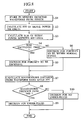
- Fig. 8 is a flowchart of processes (in the computer 7e) for monitoring a quality of lap-weld (to be free of significant porous or under-filled state) in accordance with an embodiment of the invention.
- Fig. 9 to Fig. 12 illustrate data obtained for spectral analyses of light detected by the first and second sensors 6a, 6b under the following reference welding conditions: YAG laser output, 3 kw at the welding part WP; panel members 5a, 5b, Zn-plated steel sheets 0.8 mm thick each; and welding speed, 4.5 m/min.
- the frontier of the welding part WP is melt with thermal energy of the laser beam LB3, so that the welding part WP has a melt region 26 with a keyhole 25, which (25) is formed by a plume 28 developed therethrough and defined by the combination of a front periphery 26f as a melting part of the melt region 26 and a rear periphery 26r as a part of the melt region 26 to be re-solidified.
- the plume 28 and wall of the keyhole 25 are very hot, and radiate visible rays of light and infrared rays, which are detected by the first and second sensors 6a and 6b ( Fig. 1 ) of the weld quality monitoring system QMS, together with such rays of laser beam LB3 that are reflected from the wall of keyhole 25.
- those rays of light detected by the first and second sensors 6a and 6b enter the diffraction systems DS1 and DS2 ( Fig. 3 ) in the sensors 6a and 6b, where they are diffracted into four optical analog detection signals L11 (YAG laser light 1.06 ⁇ m, in L1), L12 (visible light under 500 nm, in L1) and L21 (YAG laser light 1.06 ⁇ m, in L2), L22 (visible light under 500 nm, in L2), which are processed by the signal processing lines PL (PL1a, PL1b and PL2a, PL2b) ( Fig.
- the optical detection signals L11, L12 and L21, L22 strike on the photo-diodes 8a, 9a and 8b, 9b of the sensors 6a and 6b, respectively, where they are converted into four electrical analog detection signals E11, E12 and E21, E22 ( Fig. 3 ), which are input to the measuring circuits MC (71a, 71b and 72a, 72b) ( Fig.
- amplified detection signals Ea are processed, on the one hand, by four processing circuits 73 respectively including A/D converters 7b to provide a group of four digital detection signals Eb (whole spectral components), and on the other hand, by four processing circuits 74 respectively including band-pass filters 7c and A/D converters 7d to provide another group of four digital detection signals Ed (exclusive spectral components).
- step S1 Fig. 8
- four sets of thus obtained signals Eb, Ed are sampled in order by the computer 7e, and stored in the memory 7g, as four sets of digital data on respective waveforms of analog detection signals L11, L12 and L21, L22 (or E11, E12 and E21, E22), which represent varying intensities (as densities of flux) of such diffracted components of detected light L1 and L2 that reside in wavelength bands ( ⁇ 500 nm; ⁇ 1.06 ⁇ m) defined by combination of dichroic mirror 10 and interference filter 11 ( Fig. 3 ).
- Eb for L11, L12 and L21, L22
- Ed for L11, L12 and L21, L22
- selected one for example, Ed for L11
- Ed for L11
- selected one for example, Ed for L11
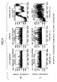
- Fig. 9 is a set of waveform graphs (by .txtPpk or .txtPp) of stored data (item nos. 40962B and 40962) on intensities of filtered infrared rays of light from the welding part WP, i.e., on electrical detection signals (Eb for L11 and L21) obtained from reflection substantially of YAG laser beam LB3 (at the wall part 26i in keyhole 25 and the top 26j of melt region 26, and though a little, radiation from the plume 28 and melt region 26) under the above-noted reference welding conditions (for beads of article), as the data are sampled in the computer 7e at a sampling frequency of 20 kHz.
- electrical detection signals Eb for L11 and L21
- the ordinate and abscissa represent a signal intensity (amplitude) and a lapse time, respectively
- reference characters YH and YL denote data on temporal variations of infrared reflection intensities caught by the first sensor 6a high of observation angle and the second sensor 6b low of observation angle, respectively.
- Fig. 9 shown by graphs at the left are data of a bead section (LH6810) with a conforming quality of weld (OK WAVEFORM), central ones are data of a bead section (LH#15) with a significant porous state (B8 BLOW NG), and right ones are data of a bead section (RH#15) with an under-filled state (B5Under).
- under-filled bead section its YH and YL waveforms are apparently different from those of conforming bead section, so that the decision for an under-filled state can be easily made.
- porous bead section of which YH and YL waveforms appear little different from those of conforming bead section, it is difficult for a simple comparison of the former with the latter to give an ensured decision for the former to be porous.
- Fig. 10 is a set of waveform graphs (by .txtPpk or .txtPp) of stored data (item nos. 4096B and 4096) on intensities of visible rays of light from the welding part WP, i.e., on electrical detection signals (Eb for L12 and L22) obtained from radiation substantially from the plume 28 and melt region 26 (and though a little, reflection at the wall part 26i in keyhole 25 and the top 26j of melt region 26) under the above-noted reference welding conditions (for the beads of article), as the data are sampled in the computer 7e at a sampling frequency of 20 kHz.
- electrical detection signals Eb for L12 and L22
- Fig. 9 shown by graphs at the left are data of the bead section (LH6810) with a conforming quality of weld (OK WAVEFORM), central ones are data of the bead section (LH#15) with a significant porous state (B8 BLOW NG), and right ones are data of the bead section (RH#15) with an under-filled state (B5Under).
- under-filled bead section its PH and PL waveforms are apparently different from those of conforming bead section, so that the decision for an under-filled state can be easily made.
- porous bead section of which PH and PL waveforms appear little different from those of conforming bead section, it is difficult for a simple comparison of the former with the latter to give an ensured decision for the former to be porous.
- waveform data stored in the memory 7g data on YH waveforms (Eb for L11 of 40962B and 40962) as temporal variations of infrared reflection caught by the first sensor 6a high of observation angle are read in the computer 7e, where they are processed by a programmed operator for calculating an FFT (high-speed Fourrier transform) of their signal intensities to provide frequency characteristics of the YH waveforms, each as a spectral distribution of signal power over a specified frequency range (0 to 2000 x 50 Hz).
- FFT high-speed Fourrier transform
- Fig. 11 shows a set of power distribution waveform graphs of thus obtained data (FFT of YH).
- the ordinate and abscissa represent a level of relative signal power and a frequency, respectively.
- the relative signal power (sometimes simply called “signal power", as used herein) is a dimensionless index indicating how much the integration of power of signal components amounts within an associated quantization slot of frequency.
- the FFT operation of signal intensity provides a distribution of relative signal power which has a significant difference even between conforming bead section (LH6810) and porous bead section (LH#15).
- the power distribution of conforming bead section has significant peaks of relative signal power within a frequency range of 100 Hz to 500 Hz, while that of porous bead section has significant peaks of relative signal power within a frequency range of 0 Hz to 1000 Hz.
- such a difference of power distribution is evaluated for the weld quality monitoring to be ensured, in the following manner.
- a set ⁇ x ijk ⁇ of associated dimensionless indices x ijk is processed together with a corresponding set ⁇ x ij0 ⁇ of standard data x ij0 to determine an (m x m) correlation matrix R(r mm ) therebetween and an (m x m) inverse matrix A(a mm ) of the correlation matrix R(r mm ), where "m" is an integer equivalent to I.
- the reference bead section may preferably be a conforming one of observed bead sections, so that data of this bead section can be conveniently re-used.
- the Maharanobis distance in terms of D kj or D kj 2 is an algebraic distance representing how far a set of characteristic quantity of the FFT signal power waveform at a current welding part of a bead section under observation (e.g. 40962) is spaced from that of the reference bead section, in a vector filed normalized relative to the set of characteristic quantities of signal power waveform of the reference bead section.
- a decision based on such a distribution of Maharanobis distances as to whether or not the bead section under observation has at the current welding part a Maharanobis distance exceeding a threshold or reference value 1000. If the Maharanobis distance is in excess (YES), the control flow goes to a step S9, where a decision is made for an under-filled state to occur. Unless it is so, the flow goes to a step S10, where a decision is made for no under-filled state to occur.
- this embodiment is described of the case of welding conditions on sheet thickness to be 0.8 mm and welding speed to be 4.5 m/min. It will be understood that a weld quality monitoring method or system according to this invention is applicable also to welding speed and/or sheet thickness else than described.
- the particular frequency band associated with the decision for a porous state to occur may preferably be varied. This is because, along with variation of welding speed and/or sheet thickness, the particular frequency band to be effective for decision of porous state varies. In order for the decision of porous state to have a maintained accuracy, an optimal frequency band therefor is selected, as it varies in dependence on welding speed and/or sheet thickness.
- the signal power rose high in a frequency band of 0 Hz to 1000 Hz for a sheet thickness sum of 1.6 mm, a frequency band of 0 Hz to 800 Hz for a sheet thickness sum of 1.8 mm, a frequency band of 0 Hz to 700 Hz for a sheet thickness sum of 2.0 mm, and a frequency band of 0 Hz to 500 Hz for a sheet thickness sum of 2.4 mm.
- the quality monitor QM of measuring system MS ( Fig. 4 ) has stored in the memory 7g such a relationship between sheet thickness sum and frequency as shown in Fig. 13 .
- the signal power rose high in a frequency band of 0 Hz to 1000 Hz at a welding speed of 3.5 m/min, a frequency band of 0 Hz to 800 Hz at a welding speed of 4.0 m/min, a frequency band of 0 Hz to 700 Hz at a welding speed of 4.5 m/min, and a frequency band of 0 Hz to 600 Hz at a welding speed of 5.0 m/min.
- the signal power rose high in a frequency band of 0 Hz to 800 Hz at a welding speed of 3.0 m/min, a frequency band of 0 Hz to 700 Hz at a welding speed of 3.5 m/min, and a frequency band of 0 Hz to 600 Hz at a welding speed of 4.0 m/min.
- the quality monitor QM of measuring system MS ( Fig. 4 ) has stored in the memory 7g such a relationship between sheet thickness sum and frequency as shown in Fig. 13 , and such a relationship between welding speed and frequency as shown in Fig. 14 for various sheet thickness sums, as a set of data listed in the form of a Table-1 shown in Fig. 15 .
- the Table-1 has various welding speeds listed in a matrix of addresses defined by combination of a row of different thickness t1 ( Fig. 16 ) of upper sheet 5a and a column of different thickness t2 ( Fig.
- an address of welding speed 3.5 m/min defined by combination of an upper sheet thickness t1 of 1.2 mm and a lower sheet thickness t2 of 0.8 mm leads to a frequency band of 0 Hz to 800 Hz to be effective for use at the welding speed 3.5 m/min for a sheet thickness sum of 2.0 mm, as shown in Fig. 14 .
- an address of welding speed 5.0 m/min defined by combination of an upper sheet thickness t1 of 0.8 mm and a lower sheet thickness t2 of 0.8 mm leads to a frequency band of 0 Hz to 600 Hz to be effective for use at the welding speed 5.0 m/min for a sheet thickness sum of 1.6 mm, as shown in Fig. 14 .
- the frequency to be effective for a decision of porous state varies in dependence on variations of nominal sheet thickness and welding speed, which may well be associated with a difference in configuration of the melt region 26 or keyhole 25 ( Fig. 5 ) in analysis of weld quality.
- Fig. 16 describes this mechanism.
- lapped sheets 5a, 5b Upon irradiation of YAG laser beam, lapped sheets 5a, 5b have a melt region 26 with keyhole, of which the configuration varies in dependence on an apparent sheet thickness sum and welding speed, so that it has a greater depth H (i.e. elongated or increased in an aspect ratio H/D relative to its width D), as the sheet thickness sum increases, or has a smaller width D (i.e. elongated either, but decreased in the aspect ratio H/D), as the welding speed increases.
- the apparent sheet thickness sum equals to a sum of t1 + t2 + g (an inter-sheet gap), i.e., the nominal sheet thickness sum (t1 + t2) + the inter-sheet gap (g).
- the depth H equals to the apparent sum.
- the nominal sum is used, as the stored data is for a typical welding, where the inter-sheet gap is properly set.
- the frequency to be effective for a decision of porous state is lowered, either when the sheet thickness (sum) increases or when the welding speed increases. This is partly because of an increased aspect ratio H/D due either to an increased sheet thickness (sum) or an increased welding speed, accompanying a melt region with keyhole to be elongate with a lowered resonance frequency, thus resulting in a reduced frequency band where the signal power tends to rise.
- a melt region with keyhole as a configuration model to be based on for determination of aspect ratio H/D, to thereby determine an effective frequency for a decision of porous state.
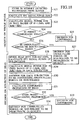
- the weld quality monitoring system and an associated welding system in the second embodiment are identical to those (QMS and WS in Figs. 1 to 4 ) of the first embodiment, providing that a personal computer 7e is adapted, by programs to be read therein from a memory 7g, for necessary functions to execute various processes described herein, including: in addition to functions in the first embodiment, a function for calculating a value of signal power in a respective one of three frequency bands, that is, a first frequency band for detecting an under-filled state, a second frequency band for detecting a porous state, and a third frequency band for detecting a non-welded state; a function for making a decision for a respective one of a conforming state, an under-filled state, a porous state, and a non-welded state to occur; and a function for dividing (a region covering) a set of data on time-dependant variations of electrical detection signals stored for a respective welding part, into a plurality of (sub-regions covering) subsets thereof in the
- Fig. 18 is a flowchart of processes (in the computer 7e) for monitoring a quality of lap-weld to be free of significant under-filled, porous, or non-welded state.
- Fig. 19 to Fig. 21 illustrate data obtained for spectral analyses of light detected by first and second sensors 6a, 6b under the following reference welding conditions: YAG laser output, 3 kw at a welding part WP; panel members 5a, 5b, Zn-plated steel sheets 0.8 mm thick each; and welding speed, 4.5 m/min.
- a non-welded state which is a non-conforming state of weld unable to provide a required weld strength.
- Fig. 17 shows a typical non-welded state between a pair of upper and lower panel members (i.e. Zn-plated steel sheets) 5a, 5b lapped to be welded.
- the non-welded state is caused by an excessive inter-sheet gap 40, which obstructs sufficient heat transmission to the lower member 5b, resulting in an insufficient melting at the welding part.
- the welding part WP has a melt region 26 with a keyhole 25 formed by a plume 28 developed therethrough.
- the plume 28 and wall of the keyhole 25 are very hot, and radiate visible rays of light and infrared rays, which are detected by the first and second sensors 6a and 6b, together with such rays of laser beam LB3 that are reflected from the wall of keyhole 25.
- Detected rays of light are converted into four electrical analog detection signals E11, E12 and E21, E22 ( Fig.
- Fig. 19 and Fig. 20 are waveform graphs of stored data on intensities of filtered infrared rays of light from the welding part WP, i.e., on electrical detection signals (Eb for L11 and L21) obtained from reflection substantially of YAG laser beam under the above-noted reference welding conditions.
- the data are sampled in the computer 7e at a sampling frequency of 20 kHz.
- the ordinate and abscissa represent a signal intensity (amplitude in voltage) and a lapse time, respectively.
- time-dependant variations of infrared reflection intensities caught by the first sensor 6a high of observation angle.
- upper and lower graphs show waveforms of signal intensity for a "conforming bead section” that has a conforming quality of weld and a "non-welded bead section” that has an incomplete weld, respectively.
- upper and lower graphs show waveforms of signal intensity for an "under-filled bead section” that has an under-filled weld and a "porous bead section” that is significant in porosity of weld, respectively.
- the under-filled bead section is different in waveform from any other bead section, so that the decision for an under-filled state can be easily made.
- the non-welded and porous bead sections appear little different in waveform from the conforming bead section, so that it is difficult to see through weld qualities of the former bead sections by observation of their waveforms.
- Fig. 21 shows a set of power distribution waveform graphs of data obtained by applying the FFT operator to the waveforms shown in Fig. 19 and Fig. 20 .
- the ordinate and abscissa represent a level of relative signal power and a frequency, respectively.
- the relative signal power is given as a dimensionless quantity (area) representing how many signal components of associated frequency are contained.
- the FFT operation of signal intensity provides a distribution of relative signal power which has a significant difference among conforming bead section, non-welded bead section, under-filled bead section, and porous bead section.
- such a difference of power distribution is evaluated for the weld quality monitoring to be ensured, in the following manner.
- waveform graphs of Fig. 21 obtained by FFT operation of signal intensities, there is set for detection of under-filled state a first frequency band ranging 0 to 1000 Hz, and, likewise, for detection of porous state a second frequency band ranging 0 to 1000 Hz.
- the setting of such frequency bands is based on experimental results that show occurrences of under-filled state and porous state can be clearly detected in those frequency bands.
- the first and second frequency bands are set to be identical in this embodiment, the (second) frequency band to be effective for detection of a porous state needs to be changed in dependence on sheet thickness (sum) and welding speed, as described in the first embodiment.
- the second frequency band for detection of porous state may preferably be changed, for example, to a range of 0 - 600 Hz.
- a third frequency band ranging 3000 Hz to 6000 Hz.
- signal power of this frequency band tends to go higher than signal power when under-filled state or porous state occurs.
- the setting of this frequency band also is based on experimental results that show occurrences of non-welded state can be clearly detected there.
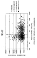
- Signal power sum of those frequency bands are determined and mapped on an imaginary two-axis coordinate system, as illustrated in Fig. 22 .
- the ordinate and abscissa represent signal power sums in the (first and second) frequency bands ranging 0 Hz to 1000 Hz, and a signal power sum in the (third) frequency band ranging 3000 Hz to 6000 Hz, respectively.
- under-filled bead section which provides such a waveform as shown in an upper right graph of Fig. 21
- this combination is mapped on a coordinate of which the ordinate and abscissa correspond to those areas.
- porous bead sections tend to be distributed within a sub-region that is relatively small of signal power sum of ordinate and relatively large of signal power sum of abscissa of the two-axis coordinate system
- non-welded bead sections tend to be distributed within a sub-region that is relatively large of signal power sum of ordinate and extends over an entire section of axis of abscissa of the two-axis coordinate system.
- conforming bead sections tend to be distributed within a sub-region that is relatively small of signal power sum of ordinate and extends over an intermediate section of axis of abscissa of the two-axis coordinate system.
- sub-region is for relative expression and may well be read simply "region”. It may depend on a result of practice how wide the width of mixing sub-region should be set.
- the imaginary region of two-axis coordinate system is prepared in the computer 7e, and those sub-regions are in no way given as actual two-dimensional planes. Although, after respective FFT operations of signal intensities, their results are mapped on the imaginary region of two-axis coordinate system, such a mapping is not actually made on a two-dimensional plane.
- Signal power sums constituting respective sub-regions have their numerical ranges, which are stored in the memory 7g, allowing for the computer 7e to make a prompt decision as to whether a non-conforming state occurs or whether an observed bead section is conforming, depending on which sub-region the result of operation belongs to.
- a step S23 on the basis of data given, while welding, on such a waveform as shown in Fig. 21 , there are calculated signal power sums in frequency bands ranging 0 Hz to 1000 Hz and 3000 Hz to 6000 Hz, respectively.
- a step S24 it is decided that a combination of coordinates in two-axis coordinate system, as it is defined by a combination of signal power sums calculated between 0 Hz to 1000 Hz and between 3000 Hz to 6000 Hz, resides in which sub-region shown in Fig. 24 .
- step S24 if the combination of coordinates belongs to a preset conforming sub-region (YES), the control flow goes to a step S25, it is decided that the welding at a welding part under observation has a conforming state (conforming bead section). On the other hand, at the step S24, unless the combination of coordinates belongs to the preset conforming sub-region (NO), the control flow goes to a step S26, where it is decided whether or not the combination of coordinates belongs to one of an under-filled sub-region, a porous sub-region, and a non-welded sub-region, as they are preset.
- step S26 if the combination of coordinates belongs to one of the under-filled sub-region, the porous sub-region, and the non-welded sub-region (YES), there should have occurred a weld state of associated sub-region, and the control flow goes to a step S27, where it is decided that the welding part under observation has a non-conforming weld quality. It is noted that the decision for a conforming bead section as well as decision for any non-conforming state of weld is indicated by a display 7f. With the foregoing process complete, an entire decision on a welding part under observation goes to an end.
- the electrical detection signal E1 output from the first sensor 6a has time-dependant variations associated therewith, of which data is stored in the memory 7g of quality monitor QM, which is read in the computer 7e, where a field of the data representing the time-dependant variations of the electrical detection signal E1 is divided into a plurality of sub-sections of the field as a temporal sequence. For example, assuming that a welding part under observation represents a section of bead 30 mm in length, as shown in Fig.
- the bead section under observation is divided into five sub-sections each having a 6 mm length, and a decision is made of a respective one of the sub-sections, for which quality of weld to occur or if it is conforming, in a manner quite identical to an upper part of the flowchart of Fig. 18 .
- this division of a data section is applied to a stored data of the electrical signal E1, it takes a time interval of 0.4 sec to weld the 30 mm bead section by a welding speed to be 4.5 m/sec in this embodiment, which means that the bead section under observation is represented by a length of stored data corresponding to a fraction of 0.4 sec of the electrical signal.
- the fraction of 0.4 sec of electrical signal is divided into a temporal sequence of sub-fractions of electrical signal each corresponding to a time slot of 0.08 sec.
- This division provides, for the bead section under observation, a sequence of data on sub-fractions of electrical signal appearing in a first sub-interval of time ranging 0 sec to 0.08 sec, a second sub-interval of time ranging 0.08 sec to 0.16 sec, a third sub-interval of time ranging 0.16 sec to 0.24 sec, a fourth sub-interval of time ranging 0.24 sec to 0.32 sec, and a fifth sub-interval of time ranging 0.32 sec to 0.4 sec.
- a conforming proportion of the bead section under observation there is calculated a conforming proportion of the bead section under observation.
- two of five sub-sections are each non-conforming in quality of weld, with the rest conforming, so that the conforming proportion is 60 %.
- a preset proportion e.g. 70%
- the control flow goes to a step S33, where it is concluded that the re-examined bead section is conforming as a whole.
- the bead section actually corresponds to a length of continuous bead preset to be longer than a required length for a sufficient weld strength, which means the actual bead section includes an allowance for probable occurrences of non-conformity, such as an under-filled, porous, and/or non-welded points. Therefore, if a section of bead under observation has a calculated conforming length exceeding the required length, the bead section may well be considered to be conforming as a whole.
- step S32 unless the number of sub-sections decided to be conforming exceeds the preset proportion (e.g. 70%) of conforming sub-section relative to the number of divided sub-sections (NO), the control flow goes to a step S34, where it is concluded that the re-examined bead section has under-filled, porous, and/or non-welded parts, so that it is non-conforming as a whole. It is noted that the display 7f indicates the conclusion of re-examined bead section to be conforming or non-conforming as a whole.
- the preset proportion e.g. 70%
- the foregoing monitoring process is performed in a real-time manner, that is, substantially at the same time as the welding. Even if the re-examination of a current welding part is performed, the conclusion is given before entering the monitoring of a subsequent welding part. If a welding part is finally concluded to be problematic in weld quality, then the welding part is marked by blasting a paint thereto. Although a fabricated vehicle body panel may have tens of welding parts, the paint marking facilitates a final inspection in a post-process. In the final inspection, paint-marked parts of any panel may well be again visually checked for non-conformity in weld quality. If a vehicle panel is concluded to be problematic in weld quality, this panel is transferred to a back-up process, where it is repaired.
- the sheet thickness sum or welding speed is kept constant.
- the second embodiment may also have a frequency (i.e. the second frequency band) varied in dependence on the sheet thickness sum, welding speed, or aspect ratio.
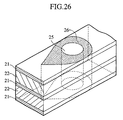
- Fig. 26 is an illustration of a vibration model of a melt region 26 formed with a keyhole 25, at a laser welding part of a lap weld between steel sheets 22 with Zn plating 21.
- the vibration model is configured like an eye drop extending upstream the welding direction in plan, and has a height equivalent to an apparent thickness sum of work (i.e. Zn-plated steel sheets 22).
- the lobe of a basic vibration of the model is open (for free vibrations) at both top and bottom surfaces of the work, and close (with forced vibrations) at a vertical center where vaporized metal of inter-sheet layers of the Zn-plating 21 is discharged as jets.
Landscapes
- Engineering & Computer Science (AREA)
- Physics & Mathematics (AREA)
- Optics & Photonics (AREA)
- Mechanical Engineering (AREA)
- Plasma & Fusion (AREA)
- Quality & Reliability (AREA)
- Laser Beam Processing (AREA)
- Investigating Materials By The Use Of Optical Means Adapted For Particular Applications (AREA)
Claims (5)
- Procédé de contrôle de qualité de soudure au laser comprenant :- le soudage d'une pièce de travail (5) avec un faisceau laser (LB1, LB2, LB3) irradié sur celle-ci à partir d'un laser YAG (1) ;- la détection d'une intensité de lumière variable (L1, L2) provenant d'un intérieur (26g) d'une périphérie frontale (26f) d'une région de fusion (26) comportant un trou de serrure (25) formé à travers dans la partie de soudage (WP) pour fournir un signal de détection ;- le traitement de données sur les signaux de détection pour calculer une transformée de Fourier rapide (FFT) de leurs intensités de signal pour fournir des caractéristiques de fréquence des signaux de détection, chacune comme un signal de distribution spectrale de puissance de signal sur une bande de fréquence spécifiée du signal de détection, où la puissance de signal est un indice adimensionnel indiquant à combien s'élève l'intégration de composantes de signal de puissance dans un créneau de quantification de fréquence associé ;- le calcul d'une somme de puissance de signal de composantes dans une bande de fréquence spécifiée du signal de détection en utilisant des données de forme d'onde après la transformée FFT d'intensités de signal ; et- l'exécution d'une décision sur l'état poreux de la partie de soudage comme étant significatif si la somme de puissance de signal dépasse un seuil de qualité de soudure, et
comme étant non significatif si la somme de puissance de signal ne dépasse pas le seuil de qualité de soudure. - Procédé de contrôle de qualité de soudure au laser selon la revendication 1, dans lequel le signal de détection comprend un signal électrique variable représentant l'intensité variable de la lumière provenant de la partie de soudage et le calcul d'une somme de puissance de signal comprend le calcul d'une somme de composantes de puissance de signal dans une bande de fréquence spécifiée du signal électrique variable.
- Procédé de contrôle de qualité de soudure au laser selon la revendication 1, dans lequel la bande de fréquence spécifiée est variée en fonction d'un parmi une épaisseur du travail, une vitesse de soudage et d'un rapport de forme d'un trou de serrure au niveau de la partie de soudage.
- Procédé de contrôle de qualité de soudure au laser selon la revendication 1,- dans lequel au moins une relation parmi une relation entre la bande de fréquence spécifiée et l'épaisseur du travail, une relation entre la bande de fréquence spécifiée et la vitesse de soudage et une relation entre la bande de fréquence spécifiée et le rapport de forme du trou de serrure au niveau de la partie de soudage est stockée dans une mémoire et la bande de fréquence spécifiée est déterminée sur la base de la relation.
- Système de contrôle de qualité de soudure au laser comprenant :- un dispositif de soudage (100) configuré pour souder une pièce de travail (5) avec un faisceau laser (LB1, LB2, LB3) irradié sur celle-ci à partir d'un laser YAG (1) ;- un détecteur (6a, 6b) configuré pour détecter une intensité variable de lumière réfléchie à partir d'un intérieur (26g) d'une périphérie frontale (26f) d'une région de fusion (26) comportant un trou de serrure (25) formé à travers dans la partie de soudage (WP) pour fournir un signal de détection ;- un déterminateur de valeurs (7) configuré pour traiter des données sur les signaux de détection pour calculer une transformée de Fourier rapide (FFT) de leurs intensités de signal pour fournir des caractéristiques de fréquence des signaux de détection, chacune comme un signal de distribution spectrale de puissance de signal sur une bande de fréquence spécifiée du signal de détection, où la puissance de signal est un indice adimensionnel indiquant à combien s'élève l'intégration de composantes de signal de puissance dans un créneau de quantification de fréquence associé, et
configuré pour calculer une somme de puissance de signal de composantes dans une bande de fréquence spécifiée du signal de détection en utilisant des données de forme d'onde après la transformée FFT d'intensités de signal ; et- un dispositif de décision configuré pour prendre une décision sur l'état poreux de la partie de soudage
comme étant significatif si la somme de puissance de signal dépasse un seuil de qualité de soudure, et
comme étant non significatif si la somme de puissance de signal ne dépasse pas le seuil de qualité de soudure.
Applications Claiming Priority (4)
| Application Number | Priority Date | Filing Date | Title |
|---|---|---|---|
| JP2001048756 | 2001-02-23 | ||
| JP2001048756 | 2001-02-23 | ||
| JP2001381889A JP3603843B2 (ja) | 2001-02-23 | 2001-12-14 | レーザー溶接部の品質モニタリング方法およびその装置 |
| JP2001381889 | 2001-12-14 |
Publications (2)
| Publication Number | Publication Date |
|---|---|
| EP1238744A1 EP1238744A1 (fr) | 2002-09-11 |
| EP1238744B1 true EP1238744B1 (fr) | 2010-04-21 |
Family
ID=26610011
Family Applications (1)
| Application Number | Title | Priority Date | Filing Date |
|---|---|---|---|
| EP02004122A Expired - Lifetime EP1238744B1 (fr) | 2001-02-23 | 2002-02-25 | Méthode et appareil de contrôle de la qualité du soudage d' un joint soudé par laser |
Country Status (4)
| Country | Link |
|---|---|
| US (1) | US6710283B2 (fr) |
| EP (1) | EP1238744B1 (fr) |
| JP (1) | JP3603843B2 (fr) |
| DE (1) | DE60236040D1 (fr) |
Cited By (1)
| Publication number | Priority date | Publication date | Assignee | Title |
|---|---|---|---|---|
| CN111032272A (zh) * | 2017-08-24 | 2020-04-17 | 株式会社Ihi检查计测 | 定位焊方法及定位焊装置 |
Families Citing this family (69)
| Publication number | Priority date | Publication date | Assignee | Title |
|---|---|---|---|---|
| US7385157B2 (en) * | 2001-04-27 | 2008-06-10 | Honda Giken Kogyo Kabushiki Kaisha | Laser beam welding method and apparatus |
| ITMI20011506A1 (it) * | 2001-07-13 | 2003-01-13 | Salvagnini Italia Spa | Sistema per il controllo della qualita' di un taglio o foratura laser, particolaramente per fogli di lamiera |
| US7344671B2 (en) * | 2003-11-26 | 2008-03-18 | Glopak Inc. | Optical sealing clamp and a method for sealing and cutting polymeric sheets with a laser |
| ITTO20040013A1 (it) * | 2004-01-13 | 2004-04-13 | Fiat Ricerche | Procedimento per il controllo della qualita' di processi industriali in particolare processi di saldatura laser |
| JP4688423B2 (ja) * | 2004-02-27 | 2011-05-25 | 独立行政法人物質・材料研究機構 | レーザ溶接方法 |
| ATE397241T1 (de) * | 2004-03-16 | 2008-06-15 | Fiat Ricerche | Verfahren und system zur qualitätüberwachung von industriellen prozessen |
| DE102004020704A1 (de) * | 2004-04-28 | 2005-11-24 | Precitec Kg | Sensorvorrichtung zur Erfassung von Strahlung aus dem Bereich einer Wechselwirkungszone zwischen einem Laserstrahl und einem Werkstück sowie Vorrichtung zur Überwachung eines Laserbearbeitungsvorgangs und Laserbearbeitungskopf |
| US7815624B2 (en) * | 2004-05-18 | 2010-10-19 | Boston Scientific Scimed, Inc. | Medical devices and methods of making the same |
| PL1610195T3 (pl) * | 2004-06-24 | 2008-09-30 | Fiat Ricerche | Sposób i układ do kontrolowania jakości procesu przemysłowego |
| US7820936B2 (en) * | 2004-07-02 | 2010-10-26 | Boston Scientific Scimed, Inc. | Method and apparatus for controlling and adjusting the intensity profile of a laser beam employed in a laser welder for welding polymeric and metallic components |
| EP1618984B1 (fr) * | 2004-07-08 | 2006-09-06 | TRUMPF Laser GmbH + Co. KG | Procédé et dispositif de soudage laser |
| DE102004041136C5 (de) * | 2004-08-25 | 2009-02-19 | Fft Edag Produktionssysteme Gmbh & Co. Kg | Verfahren und Vorrichtung zum Laserstrahl-Schweißen zum Fügen von Bauteilen, insbesondere Blechen |
| US20060096964A1 (en) * | 2004-11-08 | 2006-05-11 | Fordahl Craig A | Method and apparatus for breakthrough detection for laser workpiece processing operations |
| US8253062B2 (en) * | 2005-06-10 | 2012-08-28 | Chrysler Group Llc | System and methodology for zero-gap welding |
| US7910855B2 (en) * | 2005-09-23 | 2011-03-22 | Lasx Industries, Inc. | No gap laser welding of coated steel |
| JP5114874B2 (ja) * | 2005-09-30 | 2013-01-09 | 日産自動車株式会社 | レーザ溶接方法およびレーザ溶接装置 |
| WO2008070784A1 (fr) * | 2006-12-06 | 2008-06-12 | The Regents Of The University Of Michigan | Capteur optique pour le contrôle de qualité d'un procédé de soudage |
| EP1974849A1 (fr) * | 2007-03-28 | 2008-10-01 | Trumpf Laser- und Systemtechnik GmbH | Procédé de fixation de pièces à usiner à structure collée, en particulier destiné au blanchiment par laser de pièce à usiner collées |
| JP5011072B2 (ja) * | 2007-11-21 | 2012-08-29 | 株式会社ディスコ | レーザー加工装置 |
| TW201009525A (en) * | 2008-08-18 | 2010-03-01 | Ind Tech Res Inst | Laser marking method and laser marking system |
| US8723078B2 (en) * | 2008-11-21 | 2014-05-13 | The Regents Of The University Of Michigan | Monitoring of a welding process |
| US20100140236A1 (en) * | 2008-12-04 | 2010-06-10 | General Electric Company | Laser machining system and method |
| US7873495B2 (en) * | 2009-02-24 | 2011-01-18 | Inspectech Corporation | Welding quality control and monitoring system |
| US8506872B2 (en) * | 2009-05-29 | 2013-08-13 | Stanley Electric Co., Ltd. | Method for manufacturing resin mold assembly |
| WO2011159676A2 (fr) * | 2010-06-14 | 2011-12-22 | The Regents Of The University Of Michigan | Identification in situ et contrôle de microstructures produites par transformation de phase d'un matériau |
| JP5672480B2 (ja) * | 2010-08-30 | 2015-02-18 | スズキ株式会社 | ビードの終端部の形状を判定する装置及びその方法 |
| US10124410B2 (en) | 2010-09-25 | 2018-11-13 | Ipg Photonics Corporation | Methods and systems for coherent imaging and feedback control for modification of materials |
| EP4306235A3 (fr) | 2010-09-25 | 2024-05-08 | IPG Photonics (Canada) Inc. | Procédés et systèmes d'imagerie cohérente et de commande par rétroaction permettant une modification de matériaux |
| US20120103954A1 (en) * | 2010-11-01 | 2012-05-03 | King Fahd University Of Petroleum And Minerals | System and method for minimizing formation of striation patterns in laser cutting |
| US8661905B2 (en) * | 2010-11-09 | 2014-03-04 | Georgia Tech Research Corporation | Non-contact microelectronic device inspection systems and methods |
| SE535767C2 (sv) | 2011-04-28 | 2012-12-11 | Westinghouse Electric Sweden | Förfarande för svetsning av kärnbränslestav |
| KR101272050B1 (ko) * | 2011-11-11 | 2013-06-07 | 주식회사 성우하이텍 | 레이저 용접방법 |
| US20130153552A1 (en) * | 2011-12-14 | 2013-06-20 | Gwangju Institute Of Science And Technology | Scribing apparatus and method for having analysis function of material distribution |
| CN102615423B (zh) * | 2012-04-25 | 2014-04-02 | 湖南大学 | 基于特征光谱的镀锌钢激光添粉焊接缺陷的在线诊断方法 |
| JP5971533B2 (ja) * | 2012-05-15 | 2016-08-17 | トヨタ自動車株式会社 | 溶接方法、溶接装置、及び電池の製造方法 |
| EP2972479B1 (fr) | 2013-03-13 | 2020-09-09 | IPG Photonics (Canada) Inc. | Procédés et systèmes de caractérisation de propriétés d'usinage laser par mesure de dynamiques de trou de serrure utilisant une interférométrie |
| JP6030013B2 (ja) * | 2013-03-22 | 2016-11-24 | 株式会社東芝 | 超音波検査装置、および超音波検査方法 |
| JP5842851B2 (ja) * | 2013-03-29 | 2016-01-13 | トヨタ自動車株式会社 | 溶接部の検査装置とその検査方法 |
| US9314878B2 (en) * | 2013-09-12 | 2016-04-19 | Ford Global Technologies, Llc | Non-destructive aluminum weld quality estimator |
| CN103499579B (zh) * | 2013-10-02 | 2016-01-20 | 机械科学研究院哈尔滨焊接研究所 | 激光焊接质量快速无损检测方法 |
| CN103464906B (zh) * | 2013-10-02 | 2015-08-05 | 机械科学研究院哈尔滨焊接研究所 | 激光焊接质量在线检测方法 |
| CN103878479B (zh) * | 2014-03-06 | 2016-02-10 | 上海交通大学 | 基于光谱分析的激光焊t型搭接接头间隙的在线检测方法 |
| JP5880794B1 (ja) * | 2014-04-03 | 2016-03-09 | 新日鐵住金株式会社 | 溶接状態監視システム及び溶接状態監視方法 |
| US10099315B2 (en) * | 2014-06-27 | 2018-10-16 | Jabil Inc. | System, apparatus and method for hybrid function micro welding |
| US9851332B2 (en) * | 2014-09-19 | 2017-12-26 | King Fahd University Of Petroleum And Minerals | Process for determining weld quality using flexural characteristics |
| JP6596244B2 (ja) * | 2015-06-23 | 2019-10-23 | 株式会社総合車両製作所 | レーザ溶接方法 |
| WO2017035729A1 (fr) * | 2015-08-31 | 2017-03-09 | GM Global Technology Operations LLC | Procédé de soudage laser de pièces en aluminium |
| US20170165774A1 (en) * | 2015-12-09 | 2017-06-15 | Baziuk Holdings Ltd. | Vertical Upward Welding in Which Wire Feed is Interrupted |
| MY176094A (en) * | 2016-01-14 | 2020-07-24 | Nissan Motor | Method for detecting hole in laser-welded portion and laser welding device |
| JP2017177222A (ja) * | 2016-03-28 | 2017-10-05 | パナソニックIpマネジメント株式会社 | レーザ溶接方法およびレーザ溶接装置 |
| CN109462986B (zh) * | 2016-07-14 | 2021-01-26 | 通用汽车环球科技运作有限责任公司 | 涂层钢的多束激光点焊 |
| CN106064279A (zh) * | 2016-07-27 | 2016-11-02 | 深圳英诺激光科技有限公司 | 一种激光打标、漂白装置及其加工方法 |
| DE102017105900A1 (de) * | 2017-03-20 | 2018-09-20 | Kirchhoff Automotive Deutschland Gmbh | Verfahren zum stirnseitigen Laserschweißen |
| KR101974722B1 (ko) * | 2017-05-26 | 2019-05-02 | 전북대학교산학협력단 | 3차원 적층 가공의 실시간 가공 상태 검사와 보정 장치 및 이를 적용한 방법 |
| EP3536485A1 (fr) * | 2018-03-09 | 2019-09-11 | CL Schutzrechtsverwaltungs GmbH | Appareil de fabrication additive d'objets tridimensionnels |
| JP7126221B2 (ja) * | 2018-04-13 | 2022-08-26 | パナソニックIpマネジメント株式会社 | レーザ溶接装置 |
| EP3620292A1 (fr) * | 2018-09-07 | 2020-03-11 | Aisapack Holding SA | Procédé et dispositif de fabrication d'une soudure d'emballage |
| EP3874825A1 (fr) * | 2018-10-30 | 2021-09-08 | IDAC Holdings, Inc. | Accessibilité et mobilité à l'état de repos/inactif dans des réseaux mobiles |
| CN109353013B (zh) * | 2018-10-30 | 2021-07-20 | 大族激光科技产业集团股份有限公司 | 激光焊接塑料的监测方法 |
| CN111122568B (zh) | 2018-11-01 | 2022-04-22 | 华中科技大学苏州脑空间信息研究院 | 一种高通量光学层析成像方法及成像系统 |
| DE102018220329A1 (de) | 2018-11-27 | 2020-05-28 | Amada Holdings Co., Ltd. | Laserschweissmaschine und verfahren zur überwachung eines schweisszustands |
| CA3123038A1 (fr) | 2018-12-19 | 2020-06-25 | Ipg Photonics Corporation | Surveillance de traitement de materiau a l'aide d'une densite de signal d'imagerie determinee a partir d'une imagerie coherente en ligne (ici) |
| CN110238547B (zh) * | 2019-05-09 | 2020-12-18 | 西安理工大学 | 一种用于测量大功率激光焦点位置的系统及测量方法 |
| US11143624B2 (en) * | 2019-05-14 | 2021-10-12 | King Abdulaziz University | Detection of friction stir welding defects using specific damping capacity |
| DE102020104462A1 (de) | 2020-02-20 | 2021-08-26 | Precitec Gmbh & Co. Kg | Verfahren zum Analysieren einer Schweißverbindung beim Laserschweißen von Werkstücken |
| DE102020213109B3 (de) * | 2020-10-16 | 2022-02-10 | Trumpf Laser- Und Systemtechnik Gmbh | Verfahren und Bearbeitungsmaschine zur Porendefekt-Überwachung eines Laserschweißprozesses zum Verschweißen von mehreren Stableitern sowie zugehöriges Computerprogrammprodukt |
| DE102021208648A1 (de) | 2021-08-09 | 2023-02-09 | Robert Bosch Gesellschaft mit beschränkter Haftung | Prüfverfahren zur Prozessqualitätsüberprüfung und Prüfvorrichtung |
| CN113681194A (zh) * | 2021-08-20 | 2021-11-23 | 江苏徐工工程机械研究院有限公司 | 一种基于图像识别的多层多道焊接过程监测优化系统、方法 |
| CN115106674B (zh) * | 2022-08-25 | 2022-11-29 | 江苏华强模具科技有限公司 | 一种用于激光焊接作业的焊缝质量检测装置 |
Family Cites Families (15)
| Publication number | Priority date | Publication date | Assignee | Title |
|---|---|---|---|---|
| DE3908187A1 (de) * | 1989-03-14 | 1990-09-20 | Jurca Marius Christian | Verfahren zur qualitaetssicherung beim laserstrahlschweissen und -schneiden |
| US5121339A (en) * | 1990-08-16 | 1992-06-09 | General Motors Corporation | Laser weld fault detection system |
| DE4106007A1 (de) | 1991-02-26 | 1992-09-03 | Fraunhofer Ges Forschung | Verfahren und vorrichtung zum bearbeiten von werkstuecken mit laserstrahlung |
| US5283416A (en) | 1992-06-26 | 1994-02-01 | Trw Inc. | Laser process monitoring and evaluation |
| JP3235398B2 (ja) * | 1995-04-10 | 2001-12-04 | 日産自動車株式会社 | レーザ溶接の貫通検知方法およびその装置 |
| US5651903A (en) | 1995-10-12 | 1997-07-29 | Trw Inc. | Method and apparatus for evaluating laser welding |
| US5674415A (en) * | 1996-01-22 | 1997-10-07 | The University Of Chicago | Method and apparatus for real time weld monitoring |
| US5728992A (en) * | 1996-02-29 | 1998-03-17 | Westinghouse Electric Corporation | Apparatus and method for real time evaluation of laser welds especially in confined spaces such as within heat exchanger tubing |
| JP3209097B2 (ja) * | 1996-06-18 | 2001-09-17 | 日産自動車株式会社 | レーザ溶接の品質検査方法およびその装置 |
| DE19724986C2 (de) * | 1997-06-13 | 1999-07-29 | Jurca Optoelektronik Gmbh | Verfahren zum Verschweißen von Werkstücken und Vorrichtung zu dessen Durchführung |
| US5961859A (en) * | 1997-10-23 | 1999-10-05 | Trw Inc. | Method and apparatus for monitoring laser weld quality via plasma size measurements |
| CA2323802A1 (fr) * | 1999-01-14 | 2000-07-20 | Powerlasers Ltd. | Algorithme de filtration inverse pour la detection de defauts du soudage au laser |
| US6204469B1 (en) * | 1999-03-04 | 2001-03-20 | Honda Giken Kogyo Kabushiki Kaisha | Laser welding system |
| JP3560135B2 (ja) * | 1999-03-23 | 2004-09-02 | 日産自動車株式会社 | Yagレーザ溶接部の品質モニタリング方法 |
| KR100346090B1 (ko) * | 2000-05-30 | 2002-11-23 | 한국원자력연구소 | 레이저 용접시 용접 풀 크기감시 및 초점제어 방법 및장치 |
-
2001
- 2001-12-14 JP JP2001381889A patent/JP3603843B2/ja not_active Expired - Lifetime
-
2002
- 2002-02-25 US US10/081,153 patent/US6710283B2/en not_active Expired - Lifetime
- 2002-02-25 DE DE60236040T patent/DE60236040D1/de not_active Expired - Lifetime
- 2002-02-25 EP EP02004122A patent/EP1238744B1/fr not_active Expired - Lifetime
Cited By (1)
| Publication number | Priority date | Publication date | Assignee | Title |
|---|---|---|---|---|
| CN111032272A (zh) * | 2017-08-24 | 2020-04-17 | 株式会社Ihi检查计测 | 定位焊方法及定位焊装置 |
Also Published As
| Publication number | Publication date |
|---|---|
| US6710283B2 (en) | 2004-03-23 |
| JP3603843B2 (ja) | 2004-12-22 |
| EP1238744A1 (fr) | 2002-09-11 |
| US20020144984A1 (en) | 2002-10-10 |
| DE60236040D1 (de) | 2010-06-02 |
| JP2002321073A (ja) | 2002-11-05 |
Similar Documents
| Publication | Publication Date | Title |
|---|---|---|
| EP1238744B1 (fr) | Méthode et appareil de contrôle de la qualité du soudage d' un joint soudé par laser | |
| US6399915B1 (en) | Method and apparatus for determining quality of welding at weld between working material pieces | |
| Sun et al. | Sensor systems for real-time monitoring of laser weld quality | |
| EP0092753B1 (fr) | Détecteur à infrarouge pour soudage à l'arc | |
| US8207471B2 (en) | Method for measuring phase boundaries of a material during machining with a machining beam using additional illumination radiation and an automated image processing algorithm, and associated device | |
| JP5459922B2 (ja) | 材料加工プロセスのプロセス・パラメータを測定する方法および装置 | |
| US6329635B1 (en) | Methods for weld monitoring and laser heat treatment monitoring | |
| US5869805A (en) | Method and device for working materials using plasma-inducing laser radiation | |
| EP2543464A2 (fr) | Appareil de soudage par faisceau laser et procédé de contrôle de qualité de soudage | |
| JPH07509184A (ja) | 溶接品質モニター方法及び装置 | |
| EP1977850A1 (fr) | Dispositif de traitement et procédé de traitement de matériau | |
| JPH11221686A (ja) | プラズマサイズを測定することによるレーザ溶接部品質の監視方法及び装置 | |
| CN104002044A (zh) | 一种非熔透激光焊接设备及方法 | |
| Kratzsch et al. | Coaxial process control during laser beam welding of tailored blanks | |
| Wiesemann | 2.8 Process monitoring and closed-loop control: 2 Production engineering | |
| Abels et al. | Universal coaxial process control system for laser materials processing | |
| Park et al. | A fuzzy pattern recognition based system for monitoring laser weld quality | |
| JP2021186848A (ja) | レーザ加工装置 | |
| GB2300534A (en) | Automatic focussing of industrial laser beam | |
| JP3603829B2 (ja) | レーザ溶接の品質検査方法 | |
| Oezmert et al. | Detectability of penetration based on weld pool geometry and process emission spectrum in laser welding of copper | |
| JP2003320467A (ja) | レーザー溶接部の品質モニタリング方法およびその装置 | |
| Park et al. | Development of a weld quality monitoring system in CO 2 laser welding by using photodiodes | |
| JP3413487B2 (ja) | 溶接アーク光の影響下での動的ひずみの測定方法とその測定装置 | |
| JP2000176667A (ja) | レーザ溶接加工モニタリング装置 |
Legal Events
| Date | Code | Title | Description |
|---|---|---|---|
| PUAI | Public reference made under article 153(3) epc to a published international application that has entered the european phase |
Free format text: ORIGINAL CODE: 0009012 |
|
| 17P | Request for examination filed |
Effective date: 20020225 |
|
| AK | Designated contracting states |
Kind code of ref document: A1 Designated state(s): AT BE CH CY DE DK ES FI FR GB GR IE IT LI LU MC NL PT SE TR |
|
| AX | Request for extension of the european patent |
Free format text: AL;LT;LV;MK;RO;SI |
|
| AKX | Designation fees paid |
Designated state(s): DE FR GB |
|
| 17Q | First examination report despatched |
Effective date: 20041105 |
|
| GRAP | Despatch of communication of intention to grant a patent |
Free format text: ORIGINAL CODE: EPIDOSNIGR1 |
|
| GRAS | Grant fee paid |
Free format text: ORIGINAL CODE: EPIDOSNIGR3 |
|
| GRAA | (expected) grant |
Free format text: ORIGINAL CODE: 0009210 |
|
| AK | Designated contracting states |
Kind code of ref document: B1 Designated state(s): DE FR GB |
|
| REG | Reference to a national code |
Ref country code: GB Ref legal event code: FG4D |
|
| REF | Corresponds to: |
Ref document number: 60236040 Country of ref document: DE Date of ref document: 20100602 Kind code of ref document: P |
|
| PLBE | No opposition filed within time limit |
Free format text: ORIGINAL CODE: 0009261 |
|
| STAA | Information on the status of an ep patent application or granted ep patent |
Free format text: STATUS: NO OPPOSITION FILED WITHIN TIME LIMIT |
|
| 26N | No opposition filed |
Effective date: 20110124 |
|
| REG | Reference to a national code |
Ref country code: FR Ref legal event code: PLFP Year of fee payment: 15 |
|
| REG | Reference to a national code |
Ref country code: FR Ref legal event code: PLFP Year of fee payment: 16 |
|
| REG | Reference to a national code |
Ref country code: FR Ref legal event code: PLFP Year of fee payment: 17 |
|
| PGFP | Annual fee paid to national office [announced via postgrant information from national office to epo] |
Ref country code: FR Payment date: 20210113 Year of fee payment: 20 |
|
| PGFP | Annual fee paid to national office [announced via postgrant information from national office to epo] |
Ref country code: DE Payment date: 20210209 Year of fee payment: 20 Ref country code: GB Payment date: 20210217 Year of fee payment: 20 |
|
| REG | Reference to a national code |
Ref country code: DE Ref legal event code: R071 Ref document number: 60236040 Country of ref document: DE |
|
| REG | Reference to a national code |
Ref country code: GB Ref legal event code: PE20 Expiry date: 20220224 |
|
| PG25 | Lapsed in a contracting state [announced via postgrant information from national office to epo] |
Ref country code: GB Free format text: LAPSE BECAUSE OF EXPIRATION OF PROTECTION Effective date: 20220224 |