EP1235290A2 - Brennstoffzellen-Separator aus rostfreiem Stahl, Verfahren zu ihrer Herstellung und diesen enthaltende Festpolymer-Brennstoffzelle - Google Patents
Brennstoffzellen-Separator aus rostfreiem Stahl, Verfahren zu ihrer Herstellung und diesen enthaltende Festpolymer-Brennstoffzelle Download PDFInfo
- Publication number
- EP1235290A2 EP1235290A2 EP02004028A EP02004028A EP1235290A2 EP 1235290 A2 EP1235290 A2 EP 1235290A2 EP 02004028 A EP02004028 A EP 02004028A EP 02004028 A EP02004028 A EP 02004028A EP 1235290 A2 EP1235290 A2 EP 1235290A2
- Authority
- EP
- European Patent Office
- Prior art keywords
- mass percent
- separator
- stainless steel
- less
- steel separator
- Prior art date
- Legal status (The legal status is an assumption and is not a legal conclusion. Google has not performed a legal analysis and makes no representation as to the accuracy of the status listed.)
- Granted
Links
Images

Classifications
-
- C—CHEMISTRY; METALLURGY
- C22—METALLURGY; FERROUS OR NON-FERROUS ALLOYS; TREATMENT OF ALLOYS OR NON-FERROUS METALS
- C22C—ALLOYS
- C22C38/00—Ferrous alloys, e.g. steel alloys
- C22C38/007—Ferrous alloys, e.g. steel alloys containing silver
-
- C—CHEMISTRY; METALLURGY
- C22—METALLURGY; FERROUS OR NON-FERROUS ALLOYS; TREATMENT OF ALLOYS OR NON-FERROUS METALS
- C22C—ALLOYS
- C22C38/00—Ferrous alloys, e.g. steel alloys
- C22C38/004—Very low carbon steels, i.e. having a carbon content of less than 0,01%
-
- C—CHEMISTRY; METALLURGY
- C22—METALLURGY; FERROUS OR NON-FERROUS ALLOYS; TREATMENT OF ALLOYS OR NON-FERROUS METALS
- C22C—ALLOYS
- C22C38/00—Ferrous alloys, e.g. steel alloys
- C22C38/18—Ferrous alloys, e.g. steel alloys containing chromium
- C22C38/22—Ferrous alloys, e.g. steel alloys containing chromium with molybdenum or tungsten
-
- C—CHEMISTRY; METALLURGY
- C22—METALLURGY; FERROUS OR NON-FERROUS ALLOYS; TREATMENT OF ALLOYS OR NON-FERROUS METALS
- C22C—ALLOYS
- C22C38/00—Ferrous alloys, e.g. steel alloys
- C22C38/18—Ferrous alloys, e.g. steel alloys containing chromium
- C22C38/24—Ferrous alloys, e.g. steel alloys containing chromium with vanadium
-
- C—CHEMISTRY; METALLURGY
- C22—METALLURGY; FERROUS OR NON-FERROUS ALLOYS; TREATMENT OF ALLOYS OR NON-FERROUS METALS
- C22C—ALLOYS
- C22C38/00—Ferrous alloys, e.g. steel alloys
- C22C38/18—Ferrous alloys, e.g. steel alloys containing chromium
- C22C38/26—Ferrous alloys, e.g. steel alloys containing chromium with niobium or tantalum
-
- C—CHEMISTRY; METALLURGY
- C22—METALLURGY; FERROUS OR NON-FERROUS ALLOYS; TREATMENT OF ALLOYS OR NON-FERROUS METALS
- C22C—ALLOYS
- C22C38/00—Ferrous alloys, e.g. steel alloys
- C22C38/18—Ferrous alloys, e.g. steel alloys containing chromium
- C22C38/28—Ferrous alloys, e.g. steel alloys containing chromium with titanium or zirconium
-
- H—ELECTRICITY
- H01—ELECTRIC ELEMENTS
- H01M—PROCESSES OR MEANS, e.g. BATTERIES, FOR THE DIRECT CONVERSION OF CHEMICAL ENERGY INTO ELECTRICAL ENERGY
- H01M8/00—Fuel cells; Manufacture thereof
- H01M8/02—Details
-
- H—ELECTRICITY
- H01—ELECTRIC ELEMENTS
- H01M—PROCESSES OR MEANS, e.g. BATTERIES, FOR THE DIRECT CONVERSION OF CHEMICAL ENERGY INTO ELECTRICAL ENERGY
- H01M8/00—Fuel cells; Manufacture thereof
- H01M8/02—Details
- H01M8/0202—Collectors; Separators, e.g. bipolar separators; Interconnectors
- H01M8/0204—Non-porous and characterised by the material
- H01M8/0206—Metals or alloys
- H01M8/0208—Alloys
- H01M8/021—Alloys based on iron
-
- H—ELECTRICITY
- H01—ELECTRIC ELEMENTS
- H01M—PROCESSES OR MEANS, e.g. BATTERIES, FOR THE DIRECT CONVERSION OF CHEMICAL ENERGY INTO ELECTRICAL ENERGY
- H01M8/00—Fuel cells; Manufacture thereof
- H01M8/02—Details
- H01M8/0202—Collectors; Separators, e.g. bipolar separators; Interconnectors
- H01M8/0204—Non-porous and characterised by the material
- H01M8/0223—Composites
- H01M8/0228—Composites in the form of layered or coated products
-
- H—ELECTRICITY
- H01—ELECTRIC ELEMENTS
- H01M—PROCESSES OR MEANS, e.g. BATTERIES, FOR THE DIRECT CONVERSION OF CHEMICAL ENERGY INTO ELECTRICAL ENERGY
- H01M8/00—Fuel cells; Manufacture thereof
- H01M8/02—Details
- H01M8/0202—Collectors; Separators, e.g. bipolar separators; Interconnectors
- H01M8/0258—Collectors; Separators, e.g. bipolar separators; Interconnectors characterised by the configuration of channels, e.g. by the flow field of the reactant or coolant
- H01M8/026—Collectors; Separators, e.g. bipolar separators; Interconnectors characterised by the configuration of channels, e.g. by the flow field of the reactant or coolant characterised by grooves, e.g. their pitch or depth
-
- H—ELECTRICITY
- H01—ELECTRIC ELEMENTS
- H01M—PROCESSES OR MEANS, e.g. BATTERIES, FOR THE DIRECT CONVERSION OF CHEMICAL ENERGY INTO ELECTRICAL ENERGY
- H01M8/00—Fuel cells; Manufacture thereof
- H01M8/10—Fuel cells with solid electrolytes
- H01M2008/1095—Fuel cells with polymeric electrolytes
-
- H—ELECTRICITY
- H01—ELECTRIC ELEMENTS
- H01M—PROCESSES OR MEANS, e.g. BATTERIES, FOR THE DIRECT CONVERSION OF CHEMICAL ENERGY INTO ELECTRICAL ENERGY
- H01M2300/00—Electrolytes
- H01M2300/0017—Non-aqueous electrolytes
- H01M2300/0065—Solid electrolytes
- H01M2300/0082—Organic polymers
-
- H—ELECTRICITY
- H01—ELECTRIC ELEMENTS
- H01M—PROCESSES OR MEANS, e.g. BATTERIES, FOR THE DIRECT CONVERSION OF CHEMICAL ENERGY INTO ELECTRICAL ENERGY
- H01M8/00—Fuel cells; Manufacture thereof
- H01M8/02—Details
- H01M8/0202—Collectors; Separators, e.g. bipolar separators; Interconnectors
- H01M8/0247—Collectors; Separators, e.g. bipolar separators; Interconnectors characterised by the form
- H01M8/0254—Collectors; Separators, e.g. bipolar separators; Interconnectors characterised by the form corrugated or undulated
-
- Y—GENERAL TAGGING OF NEW TECHNOLOGICAL DEVELOPMENTS; GENERAL TAGGING OF CROSS-SECTIONAL TECHNOLOGIES SPANNING OVER SEVERAL SECTIONS OF THE IPC; TECHNICAL SUBJECTS COVERED BY FORMER USPC CROSS-REFERENCE ART COLLECTIONS [XRACs] AND DIGESTS
- Y02—TECHNOLOGIES OR APPLICATIONS FOR MITIGATION OR ADAPTATION AGAINST CLIMATE CHANGE
- Y02E—REDUCTION OF GREENHOUSE GAS [GHG] EMISSIONS, RELATED TO ENERGY GENERATION, TRANSMISSION OR DISTRIBUTION
- Y02E60/00—Enabling technologies; Technologies with a potential or indirect contribution to GHG emissions mitigation
- Y02E60/30—Hydrogen technology
- Y02E60/50—Fuel cells
-
- Y—GENERAL TAGGING OF NEW TECHNOLOGICAL DEVELOPMENTS; GENERAL TAGGING OF CROSS-SECTIONAL TECHNOLOGIES SPANNING OVER SEVERAL SECTIONS OF THE IPC; TECHNICAL SUBJECTS COVERED BY FORMER USPC CROSS-REFERENCE ART COLLECTIONS [XRACs] AND DIGESTS
- Y02—TECHNOLOGIES OR APPLICATIONS FOR MITIGATION OR ADAPTATION AGAINST CLIMATE CHANGE
- Y02P—CLIMATE CHANGE MITIGATION TECHNOLOGIES IN THE PRODUCTION OR PROCESSING OF GOODS
- Y02P70/00—Climate change mitigation technologies in the production process for final industrial or consumer products
- Y02P70/50—Manufacturing or production processes characterised by the final manufactured product
-
- Y—GENERAL TAGGING OF NEW TECHNOLOGICAL DEVELOPMENTS; GENERAL TAGGING OF CROSS-SECTIONAL TECHNOLOGIES SPANNING OVER SEVERAL SECTIONS OF THE IPC; TECHNICAL SUBJECTS COVERED BY FORMER USPC CROSS-REFERENCE ART COLLECTIONS [XRACs] AND DIGESTS
- Y10—TECHNICAL SUBJECTS COVERED BY FORMER USPC
- Y10T—TECHNICAL SUBJECTS COVERED BY FORMER US CLASSIFICATION
- Y10T428/00—Stock material or miscellaneous articles
- Y10T428/12—All metal or with adjacent metals
- Y10T428/12354—Nonplanar, uniform-thickness material having symmetrical channel shape or reverse fold [e.g., making acute angle, etc.]
Definitions
- This invention relates to electric components formed of conductive stainless steel having high durability and low contact resistance.
- this invention relates to a stainless steel separator for fuel cells and a method for making the same.
- the invention also relates to a solid polymer fuel cell using the stainless steel separator, which may be used as a power source of an electric vehicle or as a compact distributed power source for home use, for example.
- Fuel cells generate electricity by reaction of hydrogen with oxygen.
- a fuel cell basically has a sandwich structure including two separators for supplying hydrogen and oxygen, two electrodes (a fuel electrode and an air electrode), and an electrolyte membrane (ion-exchange membrane).
- Fuel cells are classified into phosphoric acid, molten sodium carbonate, solid electrolyte, alkaline, and solid polymer types depending on the types of electrolyte used.
- solid polymer fuel cells have the following advantages compared with molten sodium carbonate and phosphoric acid fuel cells: (1) they can operate at a significantly low temperature of about 80°C; (2) fuel cells with light and compact main frames can be designed; and (3) the fuel cells exhibit a short transient time, high fuel efficiency, and a high output density.
- solid polymer fuel cells have attracted attention as power sources for electric vehicles and as compact distributed power sources for home use.
- a solid polymer fuel cell generates electricity from hydrogen and oxygen through a polymer membrane, and has a structure shown in Fig. 2.
- a membrane-electrode assembly 1 with a thickness of several tens to several hundreds micrometers is sandwiched by separators 2 and 3 to form a unit cell which generates an electrical potential between the separators 2 and 3.
- the membrane-electrode assembly 1 is a composite of a polymer membrane and electrode supports on both surfaces of the polymer membrane. Each electrode support is formed of carbon cloth which supports an electrode material such as carbon black carrying a platinum catalyst.
- Several tens of to several hundreds of unit cells are connected in series to form a fuel cell stack.
- the separators which partition the unit cells, must function as (1) conductors carrying electrons generated; and (2) channels for oxygen (air) and hydrogen (air channels 4 and hydrogen channels 5 in Fig. 2) and channels for water and exhaust gas (air channels 4 and exhaust gas channels 5 in Fig. 2).
- each separator must have the following characteristics.
- contact resistance between the separator and the electrode membrane is preferably as small as possible because the power generating efficiency of the fuel cell decreases with generation of Joule heat as the contact resistance increases.
- the separator which functions as channels, requires workability to form these channels, air tightness, and corrosion resistance.
- the required lifetime of fuel cells for vehicles is about 5,000 hours and the required lifetime of stationary ones used as compact distributed power sources for home use is about 40,000 hours. Thus, the requirement for home use is much more severe than that for vehicles.
- Solid polymer fuel cells in use include separators formed of carbonaceous materials.
- the carbonaceous separators have the advantage of relatively low contact resistance and no corrosion and the disadvantage of poor impact resistance, poor compactness, and high production costs for formation of channels.
- the high production costs are the greatest obstacle to the broad use of fuel cells.
- use of metallic materials, particularly stainless steels, instead of the carbonaceous materials has been attempted.
- Japanese Unexamined Patent Publication No. 8-180883 discloses a metal separator that can readily form a passivation film.
- the passivation film increases the contact resistance of the separator, resulting in decreased power generating efficiency. Accordingly, the contact resistance and corrosion resistance of this metal must be improved.
- Japanese Unexamined Patent Publication No. 10-228914 discloses a metallic separator plated with gold having low contact resistance to ensure high output. If the gold plated layer is thin, the plated layer inevitably has pinholes. If the gold plated layer is thick, the separator is expensive.
- Japanese Unexamined Patent Publication No. 2000-277133 discloses a separator having improved contact resistance (conductivity).
- carbon powder is distributed on a ferritic stainless steel substrate.
- the use of the carbon powder also causes an increase in surface treatment cost. If the surface treated separator is damaged during assembly, the corrosion resistance thereof decreases significantly.
- Japanese Unexamined Patent Publication Nos. 2000-239806 and 2000-294255 disclose ferritic stainless steels for separators which intentionally contain Cu and Ni, and contain reduced amounts of impurities such as S, P, and N wherein C + N ⁇ 0.03 mass percent and 10.5 mass percent ⁇ Cr + 3 ⁇ Mo ⁇ 43 mass percent.
- Japanese Unexamined Patent Publication Nos. 2000-265248 and 2000-294256 (corresponding to Patent No.
- a fuel cell separator Since a fuel cell separator is subjected to pressing or cutting and to form gas channels, the surface state (the state of the passivation film) of the steel strip or sheet cannot be maintained after the strip or sheet is shaped into a separator or after the separator is assembled into a fuel cell. Thus, a fuel cell separator obtained by the above process must keep satisfactory characteristics.
- a stainless steel separator for fuel cells comprises gas channels including grooves and projections for partitioning the grooves, the separator having a composition comprising about 0.03 mass percent or less of carbon; about 0.03 mass percent or less of nitrogen, the total content of carbon and nitrogen being about 0.03 mass percent or less; about 16 mass percent to about 45 mass percent chromium; about 0.5 mass percent to about 3.0 mass percent molybdenum; and the balance being iron and incidental impurities, wherein the separator has a contact resistance of about 100 m ⁇ •cm 2 or less.
- the projections have an arithmetic average surface roughness Ra in the range of about 0.01 to about 1.0 ⁇ m and a maximum height Ry in the range of about 0.01 to about 20 ⁇ m.
- the stainless steel separator further comprises about 0.001 to about 0.1 mass percent silver.
- the stainless steel separator further comprises about 1.00 mass percent or less of silicon and about 1.00 mass percent or less of manganese.
- the stainless steel separator further comprises about 0.005 to about 0.5 mass percent vanadium.
- the stainless steel separator further comprises at least one of titanium and niobium in a total amount of about 0.01 to about 0.5 mass percent.
- the stainless steel separator is provided with a BA film having a thickness in the range of about 10 to about 300 nm on the surface of at least the projections.
- a method for making a stainless steel separator for fuel cells having gas channels including grooves and projections for partitioning the grooves comprises the steps of hot-rolling a slab to form a hot-rolled sheet having a predetermined thickness, the slab comprising about 0.03 mass percent or less of carbon, about 0.03 mass percent or less of nitrogen, the total content of carbon and nitrogen being about 0.03 mass percent or less, about 16 mass percent to about 45 mass percent chromium, about 0.5 mass percent to about 3.0 mass percent molybdenum, and the balance being iron and incidental impurities; annealing and pickling the hot-rolled sheet; and cutting the hot-rolled sheet to form the stainless steel separator.
- the surface roughness of the projections is adjusted so that the arithmetic average surface roughness Ra is in the range of about 0.01 to about 1.0 ⁇ m and the maximum height Ry is in the range of about 0.01 to about 20 ⁇ m.
- the method comprises the steps of hot-rolling a slab to form a hot-rolled sheet having a predetermined thickness, the slab comprising about 0.03 mass percent or less of carbon, about 0.03 mass percent or less of nitrogen, the total content of carbon and nitrogen being about 0.03 mass percent or less, about 16 mass percent to about 45 mass percent chromium, about 0.5 mass percent to about 3.0 mass percent molybdenum, and the balance being iron and incidental impurities; annealing and pickling the hot-rolled sheet; cold-rolling the hot-rolled sheet to form a cold-rolled sheet having a predetermined thickness; press-forming the cold-rolled sheet to form the stainless steel separator.
- the method further comprises the step of annealing and pickling the cold-rolled steel sheet.
- the surface roughness of the projections is adjusted so that the arithmetic average surface roughness Ra is in the range of about 0.01 to about 1.0 ⁇ m and the maximum height Ry is in the range of about 0.01 to about 20 ⁇ m.
- the stainless steel separator further comprises about 0.001 to about 0.1 mass percent silver.
- the surface roughness is adjusted by pickling the separator in aqua regia or an acid mixture before or after the cutting step.
- the surface roughness is adjusted during the press-forming step or by pickling the separator in aqua regia or an acid mixture before or after the press-forming step.
- the surface roughness is adjusted by the press-forming step wherein a mold used in this step has an arithmetic average surface roughness Ra in the range of about 0.01 to about 2.0 ⁇ m and a maximum height Ry in the range of about 0.01 to about 50 ⁇ m.
- the stainless steel separator further comprises about 1.00 mass percent or less of silicon and about 1.00 mass percent or less of manganese.
- the stainless steel separator further comprises about 0.005 to about 0.5 mass percent vanadium.
- the stainless steel separator further comprises at least one of titanium and niobium in a total amount of about 0.01 to about 0.5 mass percent.
- a BA film having a thickness in the range of about 10 to about 300 nm is formed on the surface of at least the projections of the stainless steel separator.
- a solid polymer fuel cell comprises a polymer film, electrodes, and the above-mentioned separator.
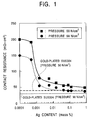
- Contact resistance was measured as follows: A cut stainless steel with a length of 50 mm and a width of 50 mm was sandwiched between carbon cloth EC-CC1-060 made by ElectroChem, Inc., which were used as supporting substrates for electrode materials, and two electrodes of gold-plated copper sheets were attached to the stainless steel. A pressure of 98 N/cm 2 or 50 N/cm 2 was applied to the composite to measure the resistance between the two electrodes.
- Fig. 1 shows the contact resistance that corresponds to the measured resistance multiplied by the contact area (25 cm 2 ).
- Fig. 1 shows that contact resistance significantly decreases to a level, which is substantially the same as that of a gold-plated SUS304 material, at a silver content exceeding 0.001 mass percent at both pressure of 98 N/cm 2 and 50 N/cm 2 .
- 50-cycle salt dry-wet combined corrosion test spraying 5 mass percent NaCl for 0.5 hour, wetting at 60°C and 95% humidity for 1 hour, and drying at 60°C for 1 hour in each cycle
- This corrosion level was the same as that of a silver-free steel sheet.
- a separator was prepared by press forming.
- the separator had 17 channel projections in contact with an electrode film (a film-electrode composite) at a space of 2 mm.
- Each channel projection had a substantially rectangular cross-section, a width of 2 mm and a height of 2 mm.
- the separator was washed with aqua regia (a 1:3 by volume mixture of nitric acid and hydrochloric acid) to control the arithmetic average surface roughness Ra within the range of 0.1 to 0.3 ⁇ m and the maximum height Ry within the range of 0.5 to 1.0 ⁇ m.
- the roughness was measured in the longitudinal direction of the channel projection according to JIS B. 0601.
- the BA film means a thin oxide film formed on the surface of the sheet during the bright annealing.
- the thickness of the BA film was measured by argon-sputtered glow discharge spectrometry. A time when the peak intensity of the emission spectrum assigned to oxygen reached 50% of the maximum value of the peak intensity of at the surface layer and a time when the peak intensity of the emission spectrum assigned to iron reached 50% of the maximum value of the peak intensity at the base metal were measured. The thickness of the film was determined by the product of the GDS sputtering rate for pure iron and the average of above two observed times.
- a SUS304 stainless steel separator having a gold plating layer with a thickness of 0.05 ⁇ m and having the above shape and a carbon separator having a thickness of 5 mm and 17 grooves with a width of 2 mm, a height of 2 mm, and an interval of 2 mm on one side and 16 lines of groves with a width of 1 mm, a height of 2 mm, and a space of 3 mm on the other side were prepared.
- separator 2 or 3 having grooves was sandwiched by square carbon cloths 7 with a side of 67 mm.
- three types of carbon cloth paper are used.
- Two gold-plated copper electrodes 6 were placed on the top and bottom and a pressure of 50 N/cm 2 was applied to measure the resistance between the two electrodes 6.
- the contact resistance was the product of the measured resistance and the contact area.
- the carbon cloths were placed to overlap the grooves. Since the contact areas differ from each other at the front and rear faces of the separator, the contact area used in this case was the average thereof.
- the contact resistance was an average of values for six stainless steel separators or for four gold-plated separators and carbon separators.
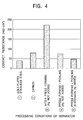
- Fig. 4 is a graph illustrating the relationship between the contact resistance and processing conditions of a separator.
- Separators 4 and 5 each having a controlled surface roughness by pickling and having an adequate BA film exhibit satisfactorily low resistance, which is comparable to that of the carbon separator.
- Separator 5 containing silver exhibited significantly low contact resistance comparable to that of the gold-plated stainless steel separator.
- Separator 3 not having a controlled surface roughness exhibited significantly high contact resistance.
- Table 1 shows that Separators 2 and 3, each having controlled surface roughness and an adequate BA film, exhibited satisfactory resistances which are equal to or less than that of the carbon separator.
- Separators 5 and 6 containing silver exhibited superior resistances comparable to that of the gold-plated stainless steel separator.
- Separator 1 not subjected to pickling for controlling the surface roughness and Separator 7 having a thick BA film (362 nm) each had a significantly high contact resistance.
- Each of separators 1 and 4 having no BA films exhibited a larger weight loss due to corrosion, though the corrosion resistance thereof is superior to that of the gold-plated stainless steel separator.
- composition of the stainless steel separator according to the invention is as follows. C: about 0.03 mass percent or less, N: about 0.03 mass percent or less, and C+N: about 0.03 mass percent or less
- the contents of these elements are as small as possible. Corrosion resistance does not decrease at a C content of about 0.03 mass percent or less, a N content of about 0.03 mass percent or less, and a total content of C and N of about 0.03 mass percent or less. If the C+N content exceeds about 0.03 mass percent, the separator will crack during cutting. Accordingly, the stainless steel separator contains about 0.03 mass percent or less of carbon, about 0.03 mass percent or less of nitrogen, and about 0.03 mass percent or less in total of carbon and nitrogen. Preferably, the stainless steel separator contains about 0.015 mass percent or less of carbon, about 0.015 mass percent or less of nitrogen, and about 0.02 mass percent or less in total of carbon and nitrogen. Si: about 1.00 mass percent or less
- the upper limit of the silicon content is about 1.00 mass percent and is preferably in the range of about 0.0005 to about 0.6 mass percent.
- Mn about 1.00 mass percent or less
- Manganese reacts with sulfur to reduce the dissolved sulfur content. Thus, manganese suppresses segregation of sulfur at the grain boundary and prevents cracking of the steel sheet during hot rolling.
- the amount of manganese for achieving such purposes is about 1.00 mass percent or less, and preferably in the range of about 0.0005 to about 0.8 mass percent.
- Cr about 16 to about 45 mass percent
- Chromium is an essential element for ensuring corrosion resistance of the stainless steel. At a chromium content of less than about 16 mass percent, the separator cannot be used for long periods of time. A chromium content exceeding about 45 mass percent decreases the toughness because of precipitation of the o phase. Thus, the chromium content is in the range of about 16 to about 45 mass percent, preferably in the range of about 20 to about 45 mass percent, and more preferably about 22 to about 35 mass percent. Mo: about 0.1 to about 3.0 mass percent
- Molybdenum is an element contributing to improved crevice corrosion resistance of the stainless steel.
- the crevice corrosion resistance is not noticeably improved at a molybdenum content of less than about 0.1 mass percent and is saturated at a molybdenum content exceeding about 3.0 mass percent.
- the molybdenum content is in the range of about 0.1 to about 3.0 mass percent, preferably about 0.5 to about 3.0 mass percent, and more preferably about 1.0 to about 2.5 mass percent.
- Silver is known as an antibacterial element, which suppresses an increase in the number of microorganisms, for example, in Japanese Unexamined Patent Publication Nos. 11-172379 and 11-12692.
- addition of a trace amount of silver to stainless steel causes decreased contact resistance and high corrosion resistance.
- Such a decrease in contact resistance is noticeable at a silver content of about 0.001 mass percent or more.
- corrosion resistance decreases and contact resistance significantly increases after corrosion occurs at a silver content exceeding about 0.1 mass percent.
- about 0.001 to about 0.1 mass percent silver is added to a contact resistance of about 100 m ⁇ •cm 2 or less under a pressure of 50 N/cm 2 .
- the silver content is in the range of about 0.005 to about 0.07 mass percent.
- Vanadium increases the corrosion resistance of the steel in a solution containing chlorides and makes silver disperse uniformly and finely during the production process of the steel making.
- the corrosion resistance increases at a vanadium content of about 0.005 mass percent or more and is saturated at a vanadium content exceeding about 0.5 mass percent.
- the vanadium content is in the range of about 0.005 to about 0.5 mass percent, preferably about 0.005 to about 0.3 mass percent, and more preferably more than about 0.2 to about 0.3 mass percent.
- Combined use of silver and vanadium is preferable because the combination thereof has synergetic effects of increased corrosion resistance and increased contact resistance of the final product.
- Ti and Nb about 0.01 to about 0.5 mass percent in total
- the press formability is noticeably improved at a titanium and niobium total content of about 0.01 mass percent and saturated at a total content exceeding about 0.5 mass percent.
- at least one of titanium and niobium is added in a total amount of about 0.01 to about 0.5 mass percent and preferably about 0.02 to about 0.4 mass percent.
- the steel sheet of the invention may contain calcium, magnesium, a rare earth metal, and boron, each in an amount of about 0.1 mass percent or less. Furthermore, the steel sheet may contain about 0.2 mass percent or less of aluminum to improve the deoxidizing rate in the molten steel and about 1 mass percent or less of nickel to improve toughness of the steel sheet. The balance of the steel is iron and incidental impurities.
- the loss due to the contact resistance becomes the joule heat, which does not contribute to generation of electricity.
- the power generating efficiency significantly decreases at a contact resistance of about 100 m ⁇ •cm 2 or more.
- the upper limit of the contact resistance is about 100 m ⁇ •cm 2 in the invention.
- Carbon cloth is used to facilitate gas diffusion and supporting the electrode member.
- the carbon cloth is integrated with a membrane-electrode assembly (MEA) or sandwiched between the MEA and the separator.
- MEA membrane-electrode assembly
- Contact resistances are known to very depending on the types of carbon cloth as demonstrated in Experimrnt 2 (Table 1). In the invention, the contact resistance is measured by using a carbon cloth EC-CC 1-060 made by Electro Chem, Inc.
- the separator 2 or 3 is sandwiched by the carbon cloths 7.
- Two gold-plated copper electrodes 6 are placed on the top and bottom and force is applied to measure the resistance between the two electrodes 6.
- the contact resistance is the product of the measured resistance and the contact area.
- the surface roughness of the metallic separator must be controlled to reduce the contact resistance thereof. Fine surface unevenness is effective for reducing the contact resistance.
- the contact resistance is equal to that of the carbon separator at an arithmetic average roughness Ra of about 0.01 ⁇ m or more, is saturated at a roughness of about 0.8 ⁇ m, and the contact resistance increases at a roughness exceeding about 1.0 ⁇ m.
- the arithmetic average roughness Ra is in the range of about 0.01 to about 1.0 ⁇ m and is preferably about 0.05 to about 0.8 ⁇ m to achieve a contact resistance of about 100 m ⁇ •cm 2 or less under a pressure of 50 N/cm 2 .
- the maximum height Ry representing the magnitude of the unevenness exceeds about 20 ⁇ m, such unevenness acts as the origin of corrosion.
- the maximum height Ry must be about 20 ⁇ m or less.
- the maximum height Ry is preferably as small as possible, the lower limit thereof is set to about 0.01 ⁇ m in view of the balance with the surface roughness Ra. Accordingly, the maximum height Ry is in the range of about 0.01 to about 20 ⁇ m.
- Surface roughness may be controlled by any method. Examples of the methods include grinding, polishing, shot blasting, laser processing, press forming, pickling, and photoetching.
- the methods suitable for mass production are press forming using a mold having a fine unevenness and pickling using hydrochloric acid or aqua regia. Pickling may be performed before or after the steel sheet is shaped into the separator. Pickling after the separator is prepared is preferable because a well-controlled surface roughness is readily prepared.
- BA film thickness about 10 to about 300 nm
- the formation of a BA film with a thickness of about 10 to about 300 nm on the stainless steel surface is effective. If the thickness of the BA film is less than about 10 nm, the corrosion resistance does not substantially improve. If the thickness exceeds about 300 nm, the contact resistance increases.
- the thickness of the BA film is in the range of about 10 to about 300 nm and preferably about 20 to about 200 nm in view of the balance between the corrosion resistance and the contact resistance.
- the BA film is formed after grooving and roughening the separator because the BA film may have defects or reduce the thickness thereof if the film is formed before grooving and roughening.
- the separator of the invention can be provided by any known method.
- the steel is formed in a converter or an electric furnace and secondarily refined by a strongly-stirred vacuum oxygen decarbonization (SS-VOD) process.
- SS-VOD strongly-stirred vacuum oxygen decarbonization
- Continuous casting is preferable in view of productivity and the quality of the resulting slab.
- the slab is hot-rolled and the hot-rolled sheet is annealed at about 800°C to about 1,150°C, pickled, and grooved by cutting to form a separator.
- the annealed hot-rolled steel sheet is further cold-rolled to form a cold-rolled sheet.
- the cold-rolled sheet is annealed at about 800°C to about 1,150°C and pickled.
- the surface roughness of the separator is preferably adjusted by grinding, polishing, shot blasting, laser processing, press forming, pickling, or photoetching to produce the final separator product. If significantly high corrosion resistance is required due to a continuous operation for a long period of time, a BA film with a thickness of about 10 to about 300 nm is preferably formed at least on the surface of the projection of the separators by bright annealing to enhance the durability in a fuel cell in use.
- Three square samples with a side of 200 mm were prepared by cutting from the center in the width direction and longitudinal direction of the resulting cold-rolled sheet and subjected to a contact resistance test and a corrosion test in diluted sulfuric acid. Separators were prepared by press forming from each steel sheet that exhibited satisfactory test results. Generating characteristics of a single cell including this separator were performed as follows.
- test pieces with sides of 50 mm were prepared by cutting each selected stainless steel sheet. As shown in Fig. 3, each test piece was sandwiched between two carbon cloths 7 having the same size and then with two gold-plated copper electrodes 6. A force of 98 N/cm 2 or 50 N/cm 2 was applied between the two electrodes 6 to measure the resistance between the electrodes 6. The contact resistance was the average of the resistances multiplied by the contact area of the four test pieces.
- a corrosion test in 5 mass percent sulfuric acid was performed according to JIS G 0591. Each test piece used in the contact resistance test was immersed in 5 mass percent sulfuric acid at 80°C for 7 days, and the weight of the test piece measured. The surface of the sample had been previously controlled by pickling. The weight loss was the average of the weight losses per unit area of the four samples.
- a unit cell shown in Fig. 2 was prepared using a square membrane-electrode assembly (MEA) 1 with a side of 67 mm composed of the separators and Nafion (made by DuPont) as a polymer film.
- the separators 2 and 3 had 17 air channels 4 and 17 hydrogen channels 5, respectively, which were arranged at an interval of 2 mm. Each channel had a square cross-section with a width of 2 mm and a height of 2 mm.
- Air and ultra-high-purity hydrogen (purity: 99.9999vol.%) were supplied to the cathode side and the anode side, respectively, to measure generating characteristic for 100 hours.
- the generating characteristic was evaluated as an output voltage at a current density of 0.7 A/cm 2 .
- the cell body was maintained at 75 ⁇ 1°C and the internal temperature of the cell was maintained at 78 ⁇ 2°C.
- the MEA and the carbon cloth were replaced with new ones for every test.
- stainless steel separators having the same shape were prepared and plated with gold (thickness: about 0.05 ⁇ m). Also, 5-mm thick carbon separators having 17 rows of grooves with a width of 2 mm, a height of 2 mm, and a space of 2 mm on one side and 16 lines of grooves with a width of 1 mm, a height of 2 mm, and a space of 3 mm on the other side were prepared. The generating characteristics of unit cells using these separators were measured according to the above conditions. Herein, each separator was arranged so that the width of the grooves was 2 mm at the side in contact with the electrode.
- Table 3 shows the results of the tests.
- Each steel sheet according to the invention exhibited low contact resistance, comparable to that of the gold-plated stainless steel sheet, and high corrosion resistance. Furthermore, the separator made of this steel sheet maintained an output voltage comparable to those of the carbon separator and the gold-plated separator during the 100-hour generating test.
- Each of the low-chromium sheet (Steel 1), the high-molybdenum sheet (Steel 10), the high-carbon sheet (Steel 12), and the high-carbon/nitrogen sheet (Steel 12) exhibited a weight loss of 0.1 g/m 2 or more, which represents poor corrosion resistance.
- a high-silver sheet (Steel 9) exhibited a significant decrease in the output voltage after 100 hours.
- Steels having compositions shown in Table 4 were prepared in a converter and by secondary refining (SS-VOD) and continuously cast to form slabs with a thickness of 200 mm. Each slab was heated to 1,250°C and hot-rolled to form a hot-rolled sheet with a thickness of 5 mm. The hot-rolled sheet was annealed at 850°C to 1,100°C and pickled. The hot-rolled sheet was used for forming separators by cutting or press forming in some cases. In the case of press forming, the sheet was cold-rolled and the cold-rolled sheet was annealed at 850°C to 1,100°C and pickled for descaling to form an annealed cold-rolled sheet with a thickness of 0.5 mm.
- SS-VOD secondary refining
- each separator had gas channels (air channels 4 and hydrogen channels 5) arranged at an interval of 1 mm, each channel having a square cross-section with a side of 2 mm.
- Each separator had an effective generation area of 45 cm 2 (groove forming area, 67 mm width ⁇ 67 mm length).
- 16 grooves with a width of 1 mm and a height of 2 mm were formed at an interval of 3 mm on the reverse face.
- the separator was pickled with aqua regia (mixture of 1:3 nitric acid/hydrochloric acid) or an acid mixture of 8 mass percent nitric acid and 2.5 mass percent hydrofluoric acid to adjust the surface roughness.
- Separators having the same shape of channels and an effective generation area of 45 cm 2 were formed by press forming and pickled with aqua regia or the above acid mixture to adjust the surface roughness (Separators 2, 7, and 8 in Table 5).
- the surface roughness was adjusted using a press mold having a surface with fine unevenness.
- Ra was 0.8 ⁇ m and Ry was 5.6 ⁇ m for Press 1
- Ra was 2.1 ⁇ m and Ry was 16.5 ⁇ m for Press 2
- Ra was 3.3 ⁇ m and Ry was 52.7 ⁇ m for Press 3.
- the methods for making the separators are summarized in Table 5.
- stainless steel separators (Separator 22 in Table 5) having the same shape were prepared and plated with gold (thickness: about 0.05 ⁇ m). Furthermore, 5-mm thick carbon separators (Separator 21 in Table 5) having 17 rows of grooves with a width of 2 mm, a height of 2 mm, and a space of 2 mm on one side and 16 lines of grooves with a width of 1 mm, a height of 2 mm, and a space of 3 mm on the other side were prepared. Four separators were prepared for each steel sheet, material, or shaping process.
- each separator was prepared by the method described below.
- the corrosion resistance of two separators among the four separators was measured in diluted sulfuric acid.
- the remaining two separators were assembled into a solid polymer fuel cell (unit cell), and the generating characteristic of the unit cell after 1,000 hour was measured.
- the grooved separator 2 or 3 as shown in Fig. 3 was sandwiched between square carbon cloths 7 having a side of 67 mm and then with two gold-plated copper electrodes 6. A force of 50 N/cm 2 was applied between the two electrodes 6 to measure the resistance between the electrodes 6.
- the contact resistance was the average of the resistances multiplied by the contact area of the four test pieces. In each test pieces, the front face and the rear face had different contact areas for the carbon cloths. Thus, the average thereof was used as the contact area of each test piece.
- a corrosion test in 10 mass percent sulfuric acid was performed according to JIS G 0591. Two test pieces for each separator were immersed in 10 mass percent sulfuric acid at 80°C for 90 days, and the weight of the test piece measured. The weight loss was the average of the weight losses per unit area of these two test pieces.
- a solid polymer fuel cell (unit cell) was prepared using an electrode film including Nafion (made by DuPont) as a polymer film for each separator. Air and ultra-high-purity hydrogen (purity: 99.9999vol.%) were supplied to the cathode side and the anode side, respectively, at a rate of 500 cm 3 /min to perform durability test measure generating characteristics for 1000 hours.
- the generating characteristic was evaluated as an output voltage at a current density of 0.6 A/cm 2 . When the decrease in the output voltage was 0.03 V or less, the separator was considered to be satisfactory.
- the cell body was maintained at 75 ⁇ 1°C and the internal temperature of the cell was maintained at 78 ⁇ 2°C.
- the MEA and the carbon cloth were replaced with new ones for every test.
- the separators according to the invention had low contact resistance, which is comparable to or superior to that of the carbon separator (Separator 21), and exhibited high corrosion resistance, which is superior to that of the gold-plated separator (Separator 22). Furthermore, fuel cells including the separators according to the invention exhibited a small decrease of 0.03 V or less in output during the 1,000-hour generating test except for Separator 17 prepared by press forming and having a surface roughness Ry exceeding 20 ⁇ m. Separator 5 prepared by cutting and not subjected to surface roughening had high contact resistance. Separator 12 using the molybdenum-free steel (Steel 7) exhibited a significantly large decrease in output voltage after the 1,000-hour generating test. Separators 14 and 15 for comparison using Steels 9 and 10, respectively, which cracked during cutting, could not be evaluated.
- hot-rolled steel sheets with a thickness of 5 mm or cold-rolled steel sheets with a thickness of 0.5 mm were prepared as in EXAMPLE 2.
- stainless steel separators (Separator 20 in Table 7) having the same shape were prepared and plated with gold (thickness: about 0.05 ⁇ m) as in EXAMPLE 2. Furthermore, 5-mm thick carbon separators (Separator 19 in Table 7) having 17 rows of grooves with a width of 2 mm, a height of 2 mm, and a space of 2 mm on one side and 16 lines of grooves with a width of 1 mm, a height of 2 mm, and a space of 3 mm on the other side were prepared. Four separators were prepared for each steel sheet or material, or shaping process. The shaping processes are shown in Table 7.
- the contact resistance of each separator was measured as in EXAMPLE 2.
- the corrosion resistance test was performed in a more severe environment as follows: A carbon sheet was placed between two grooved separators and these were subjected to a linear pressure of 9.8 N ⁇ m to provide a more severe environment compared with that in EXAMPLE 2. These were immersed in 10 mass percent sulfuric acid at 80°C for 90 days. The average weight loss of the two separators per unit area was measured. Furthermore, as in EXAMPLE 2, generating characteristics for 1,000 hours and 10,000 hours of unit fuel cells including the separators were measured. The BA film thickness was measured as in EXPERIMENT 2.
- the separators according to the invention had low contact resistance, which is comparable to or superior to that of the carbon separator (Separator 19) and exhibited high corrosion resistance, which is superior to that of the gold-plated separator (Separator 20). Furthermore, fuel cells including the separators according to the invention exhibited a small decrease of 0.03 V or less in output during the 1,000-hour generating test. Separator 4 prepared by cutting and not subjected to surface roughening and Separator 8 having a thick BA film exhibited high contact resistance. Separator 12 using the molybdenum-free steel (Steel 7) exhibited a significantly large decrease in output voltage after 650 hours. Separators 14 and 15 for comparison using Steels 9 and 10, respectively, which cracked during cutting, could not be evaluated.
- the results of a testing time of 10,000 hours are shown in Table 8.
- the separators having the BA films exhibited a decrease of 0.01 V or less in output voltage and no corrosion was observed on the disassembled separators.
- the separators having no BA films exhibited a small decrease in output voltage after 1,000 hours but a large decrease exceeding 0.03 V over about 6,000 hours.
- the stainless steel separator according to the invention suitable for use in solid polymer fuel cells has small contact resistance and high corrosion resistance which are comparable to those of known carbon separators and gold-plated stainless steel separators. Since this stainless steel separator is inexpensive compared with the carbon separators, low-cost fuel cells can be fabricated using the stainless steel separators.
- the stainless steel according to the invention can also be used as conductive stainless steel electronic components, in addition to the separators.
Applications Claiming Priority (6)
| Application Number | Priority Date | Filing Date | Title |
|---|---|---|---|
| JP2001046594 | 2001-02-22 | ||
| JP2001046594 | 2001-02-22 | ||
| JP2001354341 | 2001-11-20 | ||
| JP2001354340 | 2001-11-20 | ||
| JP2001354340 | 2001-11-20 | ||
| JP2001354341 | 2001-11-20 |
Publications (3)
| Publication Number | Publication Date |
|---|---|
| EP1235290A2 true EP1235290A2 (de) | 2002-08-28 |
| EP1235290A3 EP1235290A3 (de) | 2004-07-07 |
| EP1235290B1 EP1235290B1 (de) | 2014-07-09 |
Family
ID=27346064
Family Applications (1)
| Application Number | Title | Priority Date | Filing Date |
|---|---|---|---|
| EP02004028.3A Expired - Fee Related EP1235290B1 (de) | 2001-02-22 | 2002-02-22 | Brennstoffzellen-Separator aus rostfreiem Stahl, Verfahren zu ihrer Herstellung und diesen enthaltende Festpolymer-Brennstoffzelle |
Country Status (4)
| Country | Link |
|---|---|
| US (1) | US6835487B2 (de) |
| EP (1) | EP1235290B1 (de) |
| KR (1) | KR100488922B1 (de) |
| CA (1) | CA2372326C (de) |
Cited By (6)
| Publication number | Priority date | Publication date | Assignee | Title |
|---|---|---|---|---|
| WO2005111254A1 (en) * | 2004-05-19 | 2005-11-24 | Sandvik Intellectual Property Ab | Heat-resistant steel |
| US7070877B2 (en) | 2002-04-03 | 2006-07-04 | Nisshin Steel Co., Ltd. | Stainless steel separator for low-temperature fuel cell |
| EP1726674A1 (de) * | 2004-03-18 | 2006-11-29 | JFE Steel Corporation | Metallmaterial für stromführendes element, separator für brennstoffzelle damit und brennstoffzelle damit |
| US7385163B2 (en) | 2003-12-11 | 2008-06-10 | Automotive Componets Holdings, Llc | Fuel tank assembly and method of assembly |
| WO2009140366A2 (en) * | 2008-05-13 | 2009-11-19 | Ut-Battelle, Llc | Ferritic alloy compositions |
| EP2460900A1 (de) * | 2009-07-30 | 2012-06-06 | JFE Steel Corporation | Edelstahl für brennstoffzellenseparatoren mit hervorragender elektrischer leitfähigkeit und streckbarkeit sowie herstellungsverfahren dafür |
Families Citing this family (30)
| Publication number | Priority date | Publication date | Assignee | Title |
|---|---|---|---|---|
| JP3673747B2 (ja) * | 2001-10-25 | 2005-07-20 | 本田技研工業株式会社 | 燃料電池用セパレータ及びその製造方法 |
| US6641780B2 (en) * | 2001-11-30 | 2003-11-04 | Ati Properties Inc. | Ferritic stainless steel having high temperature creep resistance |
| JP3917442B2 (ja) * | 2002-03-14 | 2007-05-23 | 本田技研工業株式会社 | 燃料電池用金属製セパレータおよびその製造方法 |
| US7842434B2 (en) | 2005-06-15 | 2010-11-30 | Ati Properties, Inc. | Interconnects for solid oxide fuel cells and ferritic stainless steels adapted for use with solid oxide fuel cells |
| US8158057B2 (en) * | 2005-06-15 | 2012-04-17 | Ati Properties, Inc. | Interconnects for solid oxide fuel cells and ferritic stainless steels adapted for use with solid oxide fuel cells |
| US7981561B2 (en) | 2005-06-15 | 2011-07-19 | Ati Properties, Inc. | Interconnects for solid oxide fuel cells and ferritic stainless steels adapted for use with solid oxide fuel cells |
| JP4633626B2 (ja) * | 2003-09-10 | 2011-02-16 | 三菱樹脂株式会社 | 燃料電池用セパレータ |
| WO2005035816A1 (ja) * | 2003-10-07 | 2005-04-21 | Jfe Steel Corporation | 固体高分子型燃料電池セパレータ用ステンレス鋼およびそのステンレス鋼を用いた固体高分子型燃料電池 |
| JP5403642B2 (ja) * | 2003-11-07 | 2014-01-29 | 大同特殊鋼株式会社 | 耐食性導電部材 |
| EP1717329A4 (de) * | 2004-01-28 | 2007-12-26 | Nisshin Steel Co Ltd | Ferritscher nichtrostender stahl für festpolymerbrennstoffzellenseparator und festpolymerbrennstoffzelle |
| US20060257711A1 (en) * | 2005-05-12 | 2006-11-16 | Elhamid Mahmoud H A | Electrically conductive fluid distribution plate for fuel cells |
| US8017280B2 (en) | 2005-07-13 | 2011-09-13 | GM Global Technology Operations LLC | Metal fluid distribution plate with an adhesion promoting layer and polymeric layer |
| TW200721583A (en) | 2005-08-05 | 2007-06-01 | Mitsubishi Pencil Co | Separator for fuel battery and process for producing the same |
| TWM291089U (en) * | 2005-12-09 | 2006-05-21 | Antig Tech Co Ltd | Runner plate for fuel cell |
| KR100689758B1 (ko) * | 2006-04-10 | 2007-03-08 | 한국타이어 주식회사 | 연료전지용 스테인리스 강재의 제조방법 및 이에 의해제조되는 연료전지 |
| KR100882701B1 (ko) * | 2007-06-19 | 2009-02-06 | 삼성에스디아이 주식회사 | 연료전지용 세퍼레이터 및 그 제조방법과 그 세퍼레이터를채용한 연료전지 스택 |
| KR20090078550A (ko) * | 2008-01-15 | 2009-07-20 | 삼성전자주식회사 | 연료전지 및 그 연료전지에 채용되는 스택과 냉각플레이트 |
| KR100993412B1 (ko) | 2008-12-29 | 2010-11-09 | 주식회사 포스코 | 고분자 연료전지 분리판용 스테인리스강 및 그 제조방법 |
| US20100180427A1 (en) * | 2009-01-16 | 2010-07-22 | Ford Motor Company | Texturing of thin metal sheets/foils for enhanced formability and manufacturability |
| JP2010225560A (ja) * | 2009-03-25 | 2010-10-07 | Toshiba Corp | 燃料電池用セパレータ、燃料電池、および燃料電池用セパレータの製造方法 |
| US20100330389A1 (en) * | 2009-06-25 | 2010-12-30 | Ford Motor Company | Skin pass for cladding thin metal sheets |
| JP5410466B2 (ja) * | 2011-03-01 | 2014-02-05 | 株式会社神戸製鋼所 | ステンレス鋼フラックス入りワイヤ |
| JP5919920B2 (ja) * | 2011-03-28 | 2016-05-18 | Jfeスチール株式会社 | Si含有冷延鋼板の製造方法及び装置 |
| CA2876276C (en) * | 2012-07-31 | 2017-06-06 | Nippon Steel & Sumitomo Metal Corporation | Titanium or titanium alloy material for fuel cell separator having high contact conductivity with carbon and high durability, fuel cell separator including the same, and manufacturing method therefor |
| KR20160082632A (ko) * | 2014-12-26 | 2016-07-08 | 주식회사 포스코 | 고분자 연료전지용 분리판 및 그 제조방법 |
| WO2016151356A1 (fr) * | 2015-03-20 | 2016-09-29 | Aperam | Bande métallique, plaque bipolaire et procédé de fabrication associé |
| JP7172056B2 (ja) | 2018-02-28 | 2022-11-16 | トヨタ自動車株式会社 | ステンレス鋼基材、燃料電池用セパレータ及び燃料電池 |
| KR102420220B1 (ko) * | 2020-05-29 | 2022-07-13 | 주식회사 포스코 | 연료전지 분리판용 스테인리스강 |
| JP7456367B2 (ja) * | 2020-12-15 | 2024-03-27 | トヨタ自動車株式会社 | 燃料電池用のセパレータ及びその製造方法 |
| CN114875341B (zh) * | 2022-05-05 | 2023-04-21 | 宁波宝新不锈钢有限公司 | 一种燃料电池双极板用不锈钢及其制备方法 |
Family Cites Families (12)
| Publication number | Priority date | Publication date | Assignee | Title |
|---|---|---|---|---|
| US4796946A (en) * | 1987-09-04 | 1989-01-10 | Inland Steel Company | Automotive vehicle door and bar reinforcement |
| JP2686662B2 (ja) * | 1989-09-11 | 1997-12-08 | 株式会社ジャパンエナジー | 酸化物単結晶の製造装置 |
| US6440598B1 (en) * | 1997-10-14 | 2002-08-27 | Nisshin Steel Co., Ltd. | Separator for low temperature type fuel cell and method of production thereof |
| JP3269479B2 (ja) | 1999-02-24 | 2002-03-25 | 住友金属工業株式会社 | 固体高分子型燃料電池セパレータ用フェライト系ステンレス鋼 |
| JP3097690B1 (ja) | 1999-04-09 | 2000-10-10 | 住友金属工業株式会社 | 固体高分子型燃料電池 |
| JP2000328200A (ja) * | 1999-05-13 | 2000-11-28 | Sumitomo Metal Ind Ltd | 通電電気部品用オーステナイト系ステンレス鋼および燃料電池 |
| JP2001032056A (ja) | 1999-07-22 | 2001-02-06 | Sumitomo Metal Ind Ltd | 通電部品用ステンレス鋼および固体高分子型燃料電池 |
| JP3397169B2 (ja) * | 1999-04-22 | 2003-04-14 | 住友金属工業株式会社 | 固体高分子型燃料電池セパレータ用オーステナイト系ステンレス鋼および固体高分子型燃料電池 |
| CN1117882C (zh) | 1999-04-19 | 2003-08-13 | 住友金属工业株式会社 | 固体高分子型燃料电池用不锈钢材 |
| JP2000328205A (ja) | 1999-05-24 | 2000-11-28 | Sumitomo Metal Ind Ltd | 通電電気部品用フェライト系ステンレス鋼および燃料電池 |
| JP3397168B2 (ja) * | 1999-04-19 | 2003-04-14 | 住友金属工業株式会社 | 固体高分子型燃料電池セパレータ用フェライト系ステンレス鋼および固体高分子型燃料電池 |
| US6492045B1 (en) * | 2001-06-26 | 2002-12-10 | Fuelcell Energy, Inc. | Corrugated current collector for direct internal reforming fuel cells |
-
2002
- 2002-02-18 CA CA002372326A patent/CA2372326C/en not_active Expired - Fee Related
- 2002-02-19 US US10/078,737 patent/US6835487B2/en not_active Expired - Lifetime
- 2002-02-22 KR KR10-2002-0009625A patent/KR100488922B1/ko active IP Right Grant
- 2002-02-22 EP EP02004028.3A patent/EP1235290B1/de not_active Expired - Fee Related
Non-Patent Citations (1)
| Title |
|---|
| None |
Cited By (12)
| Publication number | Priority date | Publication date | Assignee | Title |
|---|---|---|---|---|
| US7070877B2 (en) | 2002-04-03 | 2006-07-04 | Nisshin Steel Co., Ltd. | Stainless steel separator for low-temperature fuel cell |
| DE10313920B4 (de) * | 2002-04-03 | 2006-12-28 | Toyota Jidosha K.K., Toyota | Edelstahlseparator für eine Niedertemperatur-Brennstoffzelle |
| US7385163B2 (en) | 2003-12-11 | 2008-06-10 | Automotive Componets Holdings, Llc | Fuel tank assembly and method of assembly |
| EP1726674A1 (de) * | 2004-03-18 | 2006-11-29 | JFE Steel Corporation | Metallmaterial für stromführendes element, separator für brennstoffzelle damit und brennstoffzelle damit |
| EP1726674A4 (de) * | 2004-03-18 | 2007-10-24 | Jfe Steel Corp | Metallmaterial für stromführendes element, separator für brennstoffzelle damit und brennstoffzelle damit |
| US8278009B2 (en) | 2004-03-18 | 2012-10-02 | Jfe Steel Corporation | Metallic material for conductive member, separator for fuel cell using the same, and fuel cell using the separator |
| WO2005111254A1 (en) * | 2004-05-19 | 2005-11-24 | Sandvik Intellectual Property Ab | Heat-resistant steel |
| WO2009140366A2 (en) * | 2008-05-13 | 2009-11-19 | Ut-Battelle, Llc | Ferritic alloy compositions |
| WO2009140366A3 (en) * | 2008-05-13 | 2010-12-16 | Ut-Battelle, Llc | Ferritic alloy compositions, interconnector plate made thereof and porous support for a sofc made thereof |
| EP2460900A1 (de) * | 2009-07-30 | 2012-06-06 | JFE Steel Corporation | Edelstahl für brennstoffzellenseparatoren mit hervorragender elektrischer leitfähigkeit und streckbarkeit sowie herstellungsverfahren dafür |
| EP2460900A4 (de) * | 2009-07-30 | 2013-03-06 | Jfe Steel Corp | Edelstahl für brennstoffzellenseparatoren mit hervorragender elektrischer leitfähigkeit und streckbarkeit sowie herstellungsverfahren dafür |
| US8440029B2 (en) | 2009-07-30 | 2013-05-14 | Jfe Steel Corporation | Stainless steel having good conductivity and ductility for use in fuel cell and method for producing the same |
Also Published As
| Publication number | Publication date |
|---|---|
| US6835487B2 (en) | 2004-12-28 |
| KR100488922B1 (ko) | 2005-05-11 |
| CA2372326A1 (en) | 2002-08-22 |
| EP1235290B1 (de) | 2014-07-09 |
| US20020160248A1 (en) | 2002-10-31 |
| CA2372326C (en) | 2007-09-11 |
| EP1235290A3 (de) | 2004-07-07 |
| KR20020068964A (ko) | 2002-08-28 |
Similar Documents
| Publication | Publication Date | Title |
|---|---|---|
| US6835487B2 (en) | Stainless steel separator for fuel cells, method for making the same, and solid polymer fuel cell including the same | |
| JP5434807B2 (ja) | 固体高分子型燃料電池用ステンレス鋼の表面粗さ調整処理方法 | |
| JP4798298B2 (ja) | 導電性と延性に優れた燃料電池セパレータ用ステンレス鋼およびその製造方法 | |
| JP4496750B2 (ja) | 固体高分子型燃料電池セパレータ用ステンレス鋼とそのステンレス鋼を用いた固体高分子型燃料電池 | |
| KR100858572B1 (ko) | 연료전지용 금속재료, 그것을 사용한 연료전지 및, 그재료의 제조방법 | |
| EP2458038A1 (de) | Edelstahl für eine brennstoffzelle mit hervorragender korrosionsbeständigkeit und herstellungsverfahren dafür | |
| JP2003223904A (ja) | 燃料電池用セパレータとその製造方法および固体高分子型燃料電池 | |
| EP2560225A1 (de) | Metallplatte zur verwendung als festkörperpolymer-brennstoffseparator | |
| WO2013018320A1 (ja) | 燃料電池セパレータ用ステンレス鋼 | |
| JP2006233282A (ja) | 電気伝導性および耐食性に優れた通電電気部品用ステンレス鋼及びその製造方法 | |
| JP3097690B1 (ja) | 固体高分子型燃料電池 | |
| JP2012177157A (ja) | 固体高分子形燃料電池セパレータ用ステンレス鋼およびその製造方法 | |
| JP3097689B1 (ja) | 固体高分子型燃料電池 | |
| US8900379B2 (en) | Stainless steel for solid polymer fuel cell separator and solid polymer typefuel cell using the stainless steel | |
| JP4340448B2 (ja) | 燃料電池セパレータ用フェライト系ステンレス鋼及びその製造方法 | |
| JP3922154B2 (ja) | 固体高分子型燃料電池セパレータ用ステンレス鋼とその製造方法および固体高分子型燃料電池 | |
| JP3269479B2 (ja) | 固体高分子型燃料電池セパレータ用フェライト系ステンレス鋼 | |
| JP4967831B2 (ja) | 固体高分子形燃料電池セパレータ用フェライト系ステンレス鋼およびそれを用いた固体高分子形燃料電池 | |
| JP4930222B2 (ja) | 固体高分子形燃料電池セパレータ用オーステナイト系ステンレス鋼およびそれを用いた固体高分子形燃料電池 | |
| JP2004002960A (ja) | 燃料電池セパレータ用オーステナイト系ステンレス鋼及びその製造方法 | |
| JP2005166276A (ja) | 固体高分子型燃料電池セパレータ用ステンレス鋼,それを用いた固体高分子型燃料電池セパレータおよび固体高分子型燃料電池 | |
| JP2005089800A (ja) | 固体高分子型燃料電池セパレータ用ステンレス鋼およびそれを用いた固体高分子型燃料電池 | |
| JP5560533B2 (ja) | 固体高分子形燃料電池セパレータ用ステンレス鋼およびそれを用いた固体高分子形燃料電池 | |
| JP2004269969A (ja) | 固体高分子型燃料電池用セパレータおよびその製造方法 | |
| JP5703560B2 (ja) | 導電性に優れた燃料電池セパレータ用ステンレス鋼板 |
Legal Events
| Date | Code | Title | Description |
|---|---|---|---|
| PUAI | Public reference made under article 153(3) epc to a published international application that has entered the european phase |
Free format text: ORIGINAL CODE: 0009012 |
|
| AK | Designated contracting states |
Kind code of ref document: A2 Designated state(s): AT BE CH CY DE DK ES FI FR GB GR IE IT LI LU MC NL PT SE TR |
|
| AX | Request for extension of the european patent |
Free format text: AL;LT;LV;MK;RO;SI |
|
| RIN1 | Information on inventor provided before grant (corrected) |
Inventor name: YOKOTA, TAKESHI, C/O KAWASAKI STEEL CORPORATION Inventor name: ISHIKAWA, SHIN, C/O KAWASAKI STEEL CORPORATION Inventor name: FURUKIMI, OSAMU, C/O KAWASAKI STEEL CORPORATION Inventor name: ISHII, KAZUHIDE, C/O KAWASAKI STEEL CORPORATION Inventor name: TAKAO, KENJI, C/O KAWASAKI STEEL CORPORATION Inventor name: TAKANO, SHIGERU, C/O KAWASAKI STEEL CORPORATION |
|
| RAP1 | Party data changed (applicant data changed or rights of an application transferred) |
Owner name: JFE STEEL CORPORATION |
|
| PUAL | Search report despatched |
Free format text: ORIGINAL CODE: 0009013 |
|
| AK | Designated contracting states |
Kind code of ref document: A3 Designated state(s): AT BE CH CY DE DK ES FI FR GB GR IE IT LI LU MC NL PT SE TR |
|
| AX | Request for extension of the european patent |
Extension state: AL LT LV MK RO SI |
|
| 17P | Request for examination filed |
Effective date: 20040806 |
|
| 17Q | First examination report despatched |
Effective date: 20050114 |
|
| AKX | Designation fees paid |
Designated state(s): DE FR GB |
|
| RIC1 | Information provided on ipc code assigned before grant |
Ipc: C22C 38/00 20060101ALI20130723BHEP Ipc: C22C 38/22 20060101ALI20130723BHEP Ipc: C22C 38/28 20060101ALI20130723BHEP Ipc: C22C 38/24 20060101ALI20130723BHEP Ipc: C22C 38/26 20060101ALI20130723BHEP Ipc: H01M 8/02 20060101AFI20130723BHEP |
|
| GRAP | Despatch of communication of intention to grant a patent |
Free format text: ORIGINAL CODE: EPIDOSNIGR1 |
|
| INTG | Intention to grant announced |
Effective date: 20131010 |
|
| RIN1 | Information on inventor provided before grant (corrected) |
Inventor name: FURUKIMI, OSAMU Inventor name: ISHII, KAZUHIDE Inventor name: TAKANO, SHIGERU Inventor name: TAKAO, KENJI Inventor name: ISHIKAWA, SHIN Inventor name: YOKOTA, TAKESHI |
|
| GRAP | Despatch of communication of intention to grant a patent |
Free format text: ORIGINAL CODE: EPIDOSNIGR1 |
|
| RIC1 | Information provided on ipc code assigned before grant |
Ipc: C22C 38/24 20060101ALI20140401BHEP Ipc: C22C 38/22 20060101ALI20140401BHEP Ipc: C22C 38/28 20060101ALI20140401BHEP Ipc: H01M 8/02 20060101AFI20140401BHEP Ipc: C22C 38/26 20060101ALI20140401BHEP Ipc: H01M 8/10 20060101ALN20140401BHEP Ipc: C22C 38/00 20060101ALI20140401BHEP |
|
| INTG | Intention to grant announced |
Effective date: 20140417 |
|
| GRAS | Grant fee paid |
Free format text: ORIGINAL CODE: EPIDOSNIGR3 |
|
| GRAA | (expected) grant |
Free format text: ORIGINAL CODE: 0009210 |
|
| AK | Designated contracting states |
Kind code of ref document: B1 Designated state(s): DE FR GB |
|
| REG | Reference to a national code |
Ref country code: GB Ref legal event code: FG4D |
|
| REG | Reference to a national code |
Ref country code: DE Ref legal event code: R096 Ref document number: 60246419 Country of ref document: DE Effective date: 20140814 |
|
| REG | Reference to a national code |
Ref country code: DE Ref legal event code: R097 Ref document number: 60246419 Country of ref document: DE |
|
| PLBE | No opposition filed within time limit |
Free format text: ORIGINAL CODE: 0009261 |
|
| STAA | Information on the status of an ep patent application or granted ep patent |
Free format text: STATUS: NO OPPOSITION FILED WITHIN TIME LIMIT |
|
| 26N | No opposition filed |
Effective date: 20150410 |
|
| REG | Reference to a national code |
Ref country code: FR Ref legal event code: PLFP Year of fee payment: 15 |
|
| REG | Reference to a national code |
Ref country code: FR Ref legal event code: PLFP Year of fee payment: 16 |
|
| PGFP | Annual fee paid to national office [announced via postgrant information from national office to epo] |
Ref country code: GB Payment date: 20170222 Year of fee payment: 16 |
|
| REG | Reference to a national code |
Ref country code: FR Ref legal event code: PLFP Year of fee payment: 17 |
|
| GBPC | Gb: european patent ceased through non-payment of renewal fee |
Effective date: 20180222 |
|
| PG25 | Lapsed in a contracting state [announced via postgrant information from national office to epo] |
Ref country code: GB Free format text: LAPSE BECAUSE OF NON-PAYMENT OF DUE FEES Effective date: 20180222 |
|
| PGFP | Annual fee paid to national office [announced via postgrant information from national office to epo] |
Ref country code: DE Payment date: 20190212 Year of fee payment: 18 Ref country code: FR Payment date: 20190111 Year of fee payment: 18 |
|
| REG | Reference to a national code |
Ref country code: DE Ref legal event code: R119 Ref document number: 60246419 Country of ref document: DE |
|
| PG25 | Lapsed in a contracting state [announced via postgrant information from national office to epo] |
Ref country code: FR Free format text: LAPSE BECAUSE OF NON-PAYMENT OF DUE FEES Effective date: 20200229 Ref country code: DE Free format text: LAPSE BECAUSE OF NON-PAYMENT OF DUE FEES Effective date: 20200901 |