EP1234976A2 - Ventilanordnung zur Druckregelung der Kraftstoffzufuhr bei einer Brennkraftmaschine - Google Patents
Ventilanordnung zur Druckregelung der Kraftstoffzufuhr bei einer Brennkraftmaschine Download PDFInfo
- Publication number
- EP1234976A2 EP1234976A2 EP01129778A EP01129778A EP1234976A2 EP 1234976 A2 EP1234976 A2 EP 1234976A2 EP 01129778 A EP01129778 A EP 01129778A EP 01129778 A EP01129778 A EP 01129778A EP 1234976 A2 EP1234976 A2 EP 1234976A2
- Authority
- EP
- European Patent Office
- Prior art keywords
- armature
- valve arrangement
- compression spring
- closing direction
- pressure
- Prior art date
- Legal status (The legal status is an assumption and is not a legal conclusion. Google has not performed a legal analysis and makes no representation as to the accuracy of the status listed.)
- Granted
Links
Images

Classifications
-
- F—MECHANICAL ENGINEERING; LIGHTING; HEATING; WEAPONS; BLASTING
- F02—COMBUSTION ENGINES; HOT-GAS OR COMBUSTION-PRODUCT ENGINE PLANTS
- F02M—SUPPLYING COMBUSTION ENGINES IN GENERAL WITH COMBUSTIBLE MIXTURES OR CONSTITUENTS THEREOF
- F02M69/00—Low-pressure fuel-injection apparatus ; Apparatus with both continuous and intermittent injection; Apparatus injecting different types of fuel
- F02M69/46—Details, component parts or accessories not provided for in, or of interest apart from, the apparatus covered by groups F02M69/02 - F02M69/44
- F02M69/54—Arrangement of fuel pressure regulators
-
- F—MECHANICAL ENGINEERING; LIGHTING; HEATING; WEAPONS; BLASTING
- F02—COMBUSTION ENGINES; HOT-GAS OR COMBUSTION-PRODUCT ENGINE PLANTS
- F02M—SUPPLYING COMBUSTION ENGINES IN GENERAL WITH COMBUSTIBLE MIXTURES OR CONSTITUENTS THEREOF
- F02M37/00—Apparatus or systems for feeding liquid fuel from storage containers to carburettors or fuel-injection apparatus; Arrangements for purifying liquid fuel specially adapted for, or arranged on, internal-combustion engines
- F02M37/0011—Constructional details; Manufacturing or assembly of elements of fuel systems; Materials therefor
- F02M37/0023—Valves in the fuel supply and return system
-
- F—MECHANICAL ENGINEERING; LIGHTING; HEATING; WEAPONS; BLASTING
- F02—COMBUSTION ENGINES; HOT-GAS OR COMBUSTION-PRODUCT ENGINE PLANTS
- F02M—SUPPLYING COMBUSTION ENGINES IN GENERAL WITH COMBUSTIBLE MIXTURES OR CONSTITUENTS THEREOF
- F02M63/00—Other fuel-injection apparatus having pertinent characteristics not provided for in groups F02M39/00 - F02M57/00 or F02M67/00; Details, component parts, or accessories of fuel-injection apparatus, not provided for in, or of interest apart from, the apparatus of groups F02M39/00 - F02M61/00 or F02M67/00; Combination of fuel pump with other devices, e.g. lubricating oil pump
- F02M63/02—Fuel-injection apparatus having several injectors fed by a common pumping element, or having several pumping elements feeding a common injector; Fuel-injection apparatus having provisions for cutting-out pumps, pumping elements, or injectors; Fuel-injection apparatus having provisions for variably interconnecting pumping elements and injectors alternatively
- F02M63/0225—Fuel-injection apparatus having a common rail feeding several injectors ; Means for varying pressure in common rails; Pumps feeding common rails
Definitions
- the invention relates to a valve arrangement for regulating the pressure of the fuel supply in an internal combustion engine with at least one pressure control device and one shut-off device operated by an electromagnetic drive.
- Such valve arrangements are particularly in engines with a direct fuel injection known.
- Such engines require injection pressures of approx. 100 to 120 bar. This pressure is generated by high pressure pumps which are very are sensitive to cavitation, d. H. the fuel supplied must be free of vapor bubbles his. In normal engine operation, a supply pressure of approximately is sufficient 4 bar around the fuel without vapor bubbles from a pre-feed pump to the high pressure pump to promote.
- the admission pressure can be increased to approx. 7 bar in order to form vapor bubbles suppress and injection pressure at engine start without effective mechanical Ensure high pressure pump.
- the required pressure increase to 7 bar is thereby by an electromagnetically actuated shut-off device and achieved by a 4 bar pressure control device arranged upstream or downstream.
- the present invention is therefore based on the object of a remedy for the to create problems described above.
- a housing is provided with at least an inlet fitting and at least one outlet fitting, the are fluidly connected to one another via a connecting channel, the electromagnetic drive by means of an armature on a plunger with a Closing element acts that the connection channel opens or closes, and at least a compression spring element that directly or indirectly in the closing direction the closing element works.
- the magnetic force acts on the armature in the closing direction of the Closing element, wherein further a compression spring, which is located on a housing part supported, acts on the anchor in the closing direction.
- a compression spring which is located on a housing part supported, acts on the anchor in the closing direction.
- this version acts it is a so-called "normally open” variant. That is, in de-energized Condition is set via the compression spring to a low pressure level of approx. 4 bar. In the energized state, a magnetic force is applied to the plunger via the armature exercised, which together with the compression spring to a high pressure level of approx. 7 bar.
- the magnetic force acts on the armature against the Closing direction of the closing element, with a first compression spring in the closing direction acts on the armature and a second compression spring in the closing direction the plunger acts and both compression springs are supported on the housing parts.
- a "currentlessly closed” variant of the valve arrangement is realized.
- the spring forces of the two compression springs add up in the de-energized state Condition to approx. 7 bar.
- the magnetic force acts against the first compression spring, so that only the second compression spring with a pressure level of approx. 4 bar acts on the plunger in the closing direction.
- a particularly simple valve arrangement results when the housing has two inlet fittings and two outlet fittings.
- the first Inlet connector is to be connected to the pre-feed pump and that second inlet fitting with the return line from the high pressure pump.
- the first outlet connector is with the inlet line of the high pressure pump and the second outlet fitting with the return line to the fuel tank connect.
- the housing can have an armature core that can be moved in the closing direction, on which the compression spring acting on the armature is supported, whereby the The pressure level of the armature can be adjusted in a simple manner.
- the electromagnetic drive is a proportional magnet system has, wherein the anchor core has an elliptical outer contour has. The pressed-in armature core is thus at the touching magnetic flux transition point not exactly circular which results in a 90 ° rotation results in a minimum and a maximum of the magnetic force, which in turn is a Force adjustment enabled.
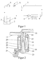
- FIG. 1 shows in schematic form the fuel flow in a not shown Internal combustion engine, wherein a pressure control of the fuel supply by means of a valve arrangement 1 according to the prior art.
- a pressure control of the fuel supply by means of a valve arrangement 1 according to the prior art.
- the fuel from a fuel tank 2 by means of a prefeed pump 3 to a high pressure pump 4, which directs the fuel at a pressure of approximately Feeds 100 to 120 bar of a fuel rail 5, one behind the rail arranged pressure regulator 6 excess fuel to a pressure regulated from up to 4 bar.
- This excess fuel is then directly or in Connection with the fuel present in the short-circuit line 7 to the valve arrangement 1 led.
- the valve arrangement 1 consists of a pressure control valve 8 and a shut-off valve 9. From the shut-off valve 9 Fuel is fed back into the fuel tank 2.
- the shut-off valve 9 is closed, so that Pressure control valve 8 that opens from a pressure number of approx. 4 bar out of operation becomes.
- the prefeed pump 3 thus delivers fuel at a pressure of approx. 7 bar, in the present case a pressure regulator 10 arranged in the fuel tank which opens at a pressure of more than 7 bar.
- the shut-off valve 9 is by means of opened an electromagnetic drive, so that now a pressure in the fuel circuit of about 4 bar is realized by the pressure control valve 8. It can Fuel before the high pressure pump 4 or after the pressure control valve 6 to the valve arrangement 1 and from there to be returned to the fuel tank 2.
- FIG. 2 now shows a first embodiment of the valve assembly according to the invention 1.
- This valve assembly 1 has an inlet fitting 11 and a Outlet connector 12, which are fluidly connected to one another via a connecting channel 13 are connected.
- the connecting channel can be closed by a closing element 14 be opened or closed.
- the closing element 14 is in a known manner arranged on a plunger 15 by an electromagnetic drive 16 is actuated and is mounted in a guide bush 20.
- the electromagnetic drive 16 consists of a known manner Coil body 17, which interacts with an electromagnetic yoke, wherein both parts are arranged in a housing 19 made of injection molding. Furthermore an armature 21 is displaceable in the longitudinal direction in a further guide bushing 20 stored. A compression spring 22 acts in the closing direction of the closing element 14 on the armature 21.
- the compression spring 22 is based on an im Housing 19 slidably arranged armature core 23 from. That way on the one hand, the spring force is set by the displaceable armature core 23 and on the other hand, if the armature core 23 has an elliptical outer contour has the magnetic force. The power supply of the electromagnetic drive guaranteed.
- valve arrangement 1 in FIG. 1 which is designed to be open when de-energized, functions in this case as follows:
- the electromagnetic drive 16 is not included Electricity supplied. Accordingly, there is no magnetic force on the armature 21 exercised.
- the valve arrangement 1 is in the “currentless open” state. Thereby owns the compression spring 22 has a low pressure level of approximately 4 bar. Will be in the fuel cycle now a system pressure of more than 4 bar is reached that opens Closing element 14 against the compression spring 22 and fuel can be in the fuel tank 2 can be returned.
- the armature 21 is through the magnetic force and the spring force are pressed against the plunger 15.
- the Magnetic force can be set so that a pressure level of approx. 7 bar is reached becomes.
- the valve arrangement 1 only opens at a pressure level in the fuel circuit, that is higher than 7 bar.
- the magnetic force is set here as already described, via the rotation of the armature core 23.
- FIG. 2 shows a cross section of a second embodiment of the valve arrangement 1.
- This valve assembly 1 has two inlet fittings 25 and 26 and two outlet fittings 27 and 28.
- the second inlet fitting 26 is with the pressure regulator 6 connected and leads excess fuel through the outlet fitting 28 back into the fuel tank 2.
- the connecting channel 13 takes over in In the present case, the function of the short-circuit line shown in Figure 1 7th
- valve arrangement 1 In contrast to the valve arrangement 1, the valve arrangement 1 according to FIG. 2 is made of Figure 1 switched "de-energized closed". That is, that in the de-energized state maximum pressure level of approx. 7 bar due to the closing force acting on the closing element 14 acts, is achieved.
- the present valve arrangement 1 has a first compression spring 29 which acts on the armature 21 in the closing direction and a second compression spring 30, which acts on the plunger 15 in the closing direction. Both Compression springs 29 and 30 are supported on housing parts and add up to maximum spring force, which corresponds to a pressure level of approx. 7 bar. In the In the starting phase, this valve arrangement 1 is therefore de-energized so that the fuel is conveyed to the high pressure pump 4 at 7 bar.
- valve arrangement 1 is energized and the magnetic force moves the armature 21 against the compression spring 29, so that only the compression spring 30 with a Pressure level of 4 bar acts on the plunger 15, so that the valve at one Pressure level that is greater than 4 bar opens and fuel through the connector 28 can be returned to the fuel tank 2.
Landscapes
- Engineering & Computer Science (AREA)
- Chemical & Material Sciences (AREA)
- Combustion & Propulsion (AREA)
- Mechanical Engineering (AREA)
- General Engineering & Computer Science (AREA)
- Fuel-Injection Apparatus (AREA)
Abstract
Description
- Figur 1
- eine schematische Ansicht des Kraftstoffflusses bei einer Brennkraftmaschine,
- Figur 2
- ein Querschnitt einer ersten Ausführungsform der erfindungsgemäßen Ventilanordnung, und
- Figur 3
- ein Querschnitt einer zweiten Ausführungsform der erfindungsgemäßen Ventilanordnung.
Claims (6)
- Ventilanordnung zur Druckregelung der Kraftstoffzufuhr bei einer Brennkraftmaschine mit zumindest einer Druckregeleinrichtung und einer durch einen elektromagnetischen Antrieb betätigbaren Absperreinrichtung, dadurch gekennzeichnet, daß ein Gehäuse (19) vorgesehen ist mit zumindest einem Einlaßanschlußstück (11, 25, 26) und zumindest einem Auslaßanschlußstück (12,27,28), die über einen Verbindungskanal (13) fluidisch miteinander verbunden sind, wobei der elektromagnetischer Antrieb (16) mittels eines Ankers (21) auf einen Stößel (15) mit einem Schließelement (14) wirkt, das den Verbindungskanal öffnet oder schließt, und mit zumindest einem Druckfederelement (22, 29,30), das direkt oder indirekt in Schließrichtung auf das Schließelement (14) wirkt.
- Ventilanordnung nach Anspruch 1, dadurch gekennzeichnet, daß die Magnetkraft auf den Anker (21) in Schließrichtung des Schließelementes (14) wirkt, wobei desweiteren eine Druckfeder (22), die sich an einem Gehäuseteil (23) abstützt, in Schließrichtung auf den Anker (21) wirkt.
- Ventilanordnung nach Anspruch 1, dadurch gekennzeichnet, daß die Magnetkraft auf den Anker (21) gegen die Schließrichtung des Schließelementes (14) wirkt, wobei eine erste Druckfeder (29) in Schließrichtung auf den Anker (21) wirkt und eine zweite Druckfeder (30) in Schließrichtung auf den Stößel (15) wirkt und sich beide Druckfedern (29, 30) an Gehäuseteilen (20, 23) abstützen.
- Ventilanordnung nach einem der vorhergehenden Ansprüche, dadurch gekennzeichnet, daß das Gehäuse (19) zwei Einlaßanschlußstücke (25, 26) und zwei Auslaßanschlußstücke (27, 28) aufweist.
- Ventilanordnung nach einem der Ansprüche 2-4, dadurch gekennzeichnet, daß das Gehäuse (19) einen in Schließrichtung bewegbaren Ankerkern (23) aufweist, an dem sich die auf den Anker (21) wirkende Druckfeder (22, 29) abstützt.
- Ventilanordnung nach Anspruch 5, dadurch gekennzeichnet, daß der elektromagnetische Antrieb (14) ein Proportional-Magnetsystem aufweist, wobei der Ankerkern (23) eine elliptische Außenkontur besitzt.
Applications Claiming Priority (2)
| Application Number | Priority Date | Filing Date | Title |
|---|---|---|---|
| DE10107618A DE10107618A1 (de) | 2001-02-17 | 2001-02-17 | Ventilanordnung zur Druckregelung der Kraftstoffzufuhr bei einer Brennkraftmaschine |
| DE10107618 | 2001-02-17 |
Publications (3)
| Publication Number | Publication Date |
|---|---|
| EP1234976A2 true EP1234976A2 (de) | 2002-08-28 |
| EP1234976A3 EP1234976A3 (de) | 2003-05-21 |
| EP1234976B1 EP1234976B1 (de) | 2006-06-21 |
Family
ID=7674501
Family Applications (1)
| Application Number | Title | Priority Date | Filing Date |
|---|---|---|---|
| EP01129778A Expired - Lifetime EP1234976B1 (de) | 2001-02-17 | 2001-12-14 | Ventilanordnung zur Druckregelung der Kraftstoffzufuhr bei einer Brennkraftmaschine |
Country Status (4)
| Country | Link |
|---|---|
| US (1) | US6659424B2 (de) |
| EP (1) | EP1234976B1 (de) |
| DE (2) | DE10107618A1 (de) |
| ES (1) | ES2266081T3 (de) |
Cited By (2)
| Publication number | Priority date | Publication date | Assignee | Title |
|---|---|---|---|---|
| WO2008149384A1 (en) * | 2007-06-08 | 2008-12-11 | Ucal Fuel Systems Limited | Variable pressure fuel injection system |
| EP2380811A1 (de) | 2010-04-23 | 2011-10-26 | Francisco Monente Plösser | Verpackungsmaschine |
Families Citing this family (8)
| Publication number | Priority date | Publication date | Assignee | Title |
|---|---|---|---|---|
| US20060118486A1 (en) * | 2004-12-06 | 2006-06-08 | Sower Larry P | Evaporation of water from a dilute waste slurry to produce a concentrated waste slurry |
| JP4535033B2 (ja) * | 2005-10-14 | 2010-09-01 | 株式会社デンソー | 減圧弁および燃料噴射装置 |
| DE102008060889B4 (de) * | 2008-12-09 | 2022-08-25 | Pierburg Gmbh | Druckregelventil |
| DE102009032365B4 (de) * | 2009-07-08 | 2011-04-28 | Pierburg Gmbh | Elektromagnetantrieb für ein Ventil |
| DE102009032367B4 (de) * | 2009-07-08 | 2011-04-28 | Pierburg Gmbh | Elektromagnetantrieb für ein Ventil |
| CN106032852B (zh) * | 2015-03-11 | 2019-10-11 | 德昌电机(深圳)有限公司 | 电磁阀 |
| CN204756101U (zh) * | 2015-06-05 | 2015-11-11 | 厦门科际精密器材有限公司 | 电磁阀 |
| DE102018222614A1 (de) * | 2018-12-20 | 2020-06-25 | Robert Bosch Gmbh | Elektromagnetische Betätigungseinrichtung |
Family Cites Families (19)
| Publication number | Priority date | Publication date | Assignee | Title |
|---|---|---|---|---|
| US3974998A (en) * | 1972-07-28 | 1976-08-17 | Crown Cork & Seal Company, Inc. | Spray coating apparatus |
| US4251051A (en) * | 1979-04-19 | 1981-02-17 | The Jacobs Manufacturing Company | Solenoid structure having a relatively unrestrained generally flat armature member |
| US5546987A (en) * | 1981-11-06 | 1996-08-20 | Sule; Akos | Solenoid valve |
| US4750704A (en) * | 1983-12-21 | 1988-06-14 | Robert W. Brundage | Solenoid controlled fluid flow valve |
| JPS60162238U (ja) * | 1984-04-05 | 1985-10-28 | 株式会社ボッシュオートモーティブ システム | 燃料噴射装置 |
| US4712767A (en) * | 1986-10-29 | 1987-12-15 | Allied Corporation | Solenoid control valve |
| IT208326Z2 (it) * | 1986-11-07 | 1988-05-28 | Altecna Azienda Della Weber S | Elettrovalvola regolatrice di pressione particolarmente per circuiti ad alta pressione di impianti di iniezione del combustibile per motori a combustione interna |
| US4998559A (en) * | 1988-09-13 | 1991-03-12 | Coltec Industries Inc. | Solenoid operated pressure control valve |
| US4971115A (en) * | 1989-07-27 | 1990-11-20 | Humphrey Products Company | Four-way poppet valve with hollow stem and four-port body |
| DE4129828C1 (de) * | 1991-09-07 | 1993-04-29 | Mercedes-Benz Aktiengesellschaft, 7000 Stuttgart, De | |
| US5462253A (en) * | 1994-07-22 | 1995-10-31 | General Motors Corporation | Dual slope flow control valve |
| EP0699859B1 (de) * | 1994-08-30 | 1998-04-08 | Pierburg Aktiengesellschaft | Elektromagnetisches Schaltventil |
| DE4431459C2 (de) * | 1994-09-03 | 2000-02-10 | Bosch Gmbh Robert | Elektromagnetventil und Verfahren zu dessen Herstellung |
| US5570721A (en) * | 1995-03-29 | 1996-11-05 | Caterpillar Inc. | Double acting solenoid and poppet valve servomechanism |
| US5626325A (en) * | 1995-09-14 | 1997-05-06 | Cummins Engine Company, Inc. | High pressure control valve for a fuel injection system |
| DE19652410C2 (de) * | 1996-12-06 | 1999-12-09 | Mannesmann Ag | Elektropneumatisches Ventil |
| US5947442A (en) * | 1997-09-10 | 1999-09-07 | Cummins Engine Company, Inc. | Solenoid actuated valve assembly |
| US6199533B1 (en) * | 1999-02-01 | 2001-03-13 | Cummins Engine Company, Inc. | Pilot valve controlled three-way fuel injection control valve assembly |
| US6279603B1 (en) * | 1998-10-01 | 2001-08-28 | Ambac International | Fluid-cooled injector |
-
2001
- 2001-02-17 DE DE10107618A patent/DE10107618A1/de not_active Withdrawn
- 2001-12-14 DE DE50110244T patent/DE50110244D1/de not_active Expired - Fee Related
- 2001-12-14 ES ES01129778T patent/ES2266081T3/es not_active Expired - Lifetime
- 2001-12-14 EP EP01129778A patent/EP1234976B1/de not_active Expired - Lifetime
-
2002
- 2002-02-05 US US10/068,206 patent/US6659424B2/en not_active Expired - Fee Related
Cited By (2)
| Publication number | Priority date | Publication date | Assignee | Title |
|---|---|---|---|---|
| WO2008149384A1 (en) * | 2007-06-08 | 2008-12-11 | Ucal Fuel Systems Limited | Variable pressure fuel injection system |
| EP2380811A1 (de) | 2010-04-23 | 2011-10-26 | Francisco Monente Plösser | Verpackungsmaschine |
Also Published As
| Publication number | Publication date |
|---|---|
| ES2266081T3 (es) | 2007-03-01 |
| US6659424B2 (en) | 2003-12-09 |
| EP1234976B1 (de) | 2006-06-21 |
| EP1234976A3 (de) | 2003-05-21 |
| US20020113220A1 (en) | 2002-08-22 |
| DE10107618A1 (de) | 2002-08-29 |
| DE50110244D1 (de) | 2006-08-03 |
Similar Documents
| Publication | Publication Date | Title |
|---|---|---|
| EP0558715B1 (de) | Elektromagnetisch betätigbares einspritzventil | |
| DE10247436A1 (de) | Dosierventil und Kraftstoffeinspritzpumpe | |
| WO2009013041A1 (de) | Hochdruckpumpe für ein kraftstoffsystem einer brennkraftmaschine | |
| DE19810867A1 (de) | Kraftstoffpumpen-Anordnung | |
| DE19630938C2 (de) | Kraftstoffzuleitung mit einem Volumenstromregelventil und Volumenstromregelventil | |
| EP1561026B1 (de) | Kraftstoffzumesseinheit für kraftstoffeinspritzanlagen von brennkraftmaschinen | |
| EP1234976B1 (de) | Ventilanordnung zur Druckregelung der Kraftstoffzufuhr bei einer Brennkraftmaschine | |
| DE102004057011B4 (de) | Kraftfahrzeug-Kraftstoffeinspritzsystem mit Steuerventil für hohen Durchsatz | |
| WO2016015912A1 (de) | Hochdruckpumpe | |
| DE112018005561B4 (de) | Hochdruckkraftstoffpumpe | |
| EP1203151A1 (de) | Zweistufiges magnetventil für einen injektor von brennkarftmaschinen | |
| DE10236387A1 (de) | Vorrichtung zum dosierten Zumischen von verflüchtigtem Kraftstoff in ein Ansaugrohr einer Brennkraftmaschine | |
| WO1999066239A1 (de) | Magnetventil | |
| EP0408915B1 (de) | Kraftstoffeinspritzpumpe für Brennkraftmaschinen | |
| DE10334474A1 (de) | Hochstrom-Steuerventil für Motorfahrzeug-Kraftstoffeinspirtzsysteme | |
| DE69607230T2 (de) | Kraftstoffeinspritzpumpensteuerung | |
| EP1278952A2 (de) | Brennstoffeinspritzventil | |
| WO2001027463A1 (de) | Injektor für ein kraftstoffeinspritzsystem für brennkraftmaschinen mit in den ventilsteuerraum ragender düsennadel | |
| EP2758653A1 (de) | Druckregelsystem und druckregelventil | |
| DE3724545A1 (de) | Kraftstoff-einspritzduese fuer brennkraftmaschinen | |
| DE19908418C1 (de) | Steuerventil zum Einsatz in einem Speichereinspritzsystem für einen Dieselmotor | |
| WO2008083882A1 (de) | Injektor zum einspritzen von kraftstoff | |
| DE102019134775B4 (de) | Magnetventil | |
| EP1861617A1 (de) | Vorrichtung zum einspritzen von kraftstoff | |
| DE102004019850A1 (de) | Elektromagnetisches Steuerventil |
Legal Events
| Date | Code | Title | Description |
|---|---|---|---|
| PUAI | Public reference made under article 153(3) epc to a published international application that has entered the european phase |
Free format text: ORIGINAL CODE: 0009012 |
|
| 17P | Request for examination filed |
Effective date: 20011214 |
|
| AK | Designated contracting states |
Kind code of ref document: A2 Designated state(s): AT BE CH CY DE DK ES FI FR GB GR IE IT LI LU MC NL PT SE TR |
|
| AX | Request for extension of the european patent |
Free format text: AL;LT;LV;MK;RO;SI |
|
| PUAL | Search report despatched |
Free format text: ORIGINAL CODE: 0009013 |
|
| AK | Designated contracting states |
Designated state(s): AT BE CH CY DE DK ES FI FR GB GR IE IT LI LU MC NL PT SE TR |
|
| AX | Request for extension of the european patent |
Extension state: AL LT LV MK RO SI |
|
| RIC1 | Information provided on ipc code assigned before grant |
Ipc: 7F 16K 31/02 B Ipc: 7F 02M 69/54 A Ipc: 7F 02M 59/46 B |
|
| 17Q | First examination report despatched |
Effective date: 20031208 |
|
| AKX | Designation fees paid |
Designated state(s): DE ES FR GB IT |
|
| GRAP | Despatch of communication of intention to grant a patent |
Free format text: ORIGINAL CODE: EPIDOSNIGR1 |
|
| GRAS | Grant fee paid |
Free format text: ORIGINAL CODE: EPIDOSNIGR3 |
|
| GRAA | (expected) grant |
Free format text: ORIGINAL CODE: 0009210 |
|
| AK | Designated contracting states |
Kind code of ref document: B1 Designated state(s): DE ES FR GB IT |
|
| REG | Reference to a national code |
Ref country code: GB Ref legal event code: FG4D Free format text: NOT ENGLISH |
|
| GBT | Gb: translation of ep patent filed (gb section 77(6)(a)/1977) |
Effective date: 20060628 |
|
| REF | Corresponds to: |
Ref document number: 50110244 Country of ref document: DE Date of ref document: 20060803 Kind code of ref document: P |
|
| ET | Fr: translation filed | ||
| REG | Reference to a national code |
Ref country code: ES Ref legal event code: FG2A Ref document number: 2266081 Country of ref document: ES Kind code of ref document: T3 |
|
| PLBE | No opposition filed within time limit |
Free format text: ORIGINAL CODE: 0009261 |
|
| STAA | Information on the status of an ep patent application or granted ep patent |
Free format text: STATUS: NO OPPOSITION FILED WITHIN TIME LIMIT |
|
| 26N | No opposition filed |
Effective date: 20070322 |
|
| PGFP | Annual fee paid to national office [announced via postgrant information from national office to epo] |
Ref country code: ES Payment date: 20081217 Year of fee payment: 8 |
|
| PGFP | Annual fee paid to national office [announced via postgrant information from national office to epo] |
Ref country code: FR Payment date: 20081212 Year of fee payment: 8 |
|
| PGFP | Annual fee paid to national office [announced via postgrant information from national office to epo] |
Ref country code: DE Payment date: 20081219 Year of fee payment: 8 |
|
| PGFP | Annual fee paid to national office [announced via postgrant information from national office to epo] |
Ref country code: GB Payment date: 20081216 Year of fee payment: 8 |
|
| PGFP | Annual fee paid to national office [announced via postgrant information from national office to epo] |
Ref country code: IT Payment date: 20081224 Year of fee payment: 8 |
|
| GBPC | Gb: european patent ceased through non-payment of renewal fee |
Effective date: 20091214 |
|
| REG | Reference to a national code |
Ref country code: FR Ref legal event code: ST Effective date: 20100831 |
|
| PG25 | Lapsed in a contracting state [announced via postgrant information from national office to epo] |
Ref country code: FR Free format text: LAPSE BECAUSE OF NON-PAYMENT OF DUE FEES Effective date: 20091231 |
|
| PG25 | Lapsed in a contracting state [announced via postgrant information from national office to epo] |
Ref country code: DE Free format text: LAPSE BECAUSE OF NON-PAYMENT OF DUE FEES Effective date: 20100701 |
|
| PG25 | Lapsed in a contracting state [announced via postgrant information from national office to epo] |
Ref country code: GB Free format text: LAPSE BECAUSE OF NON-PAYMENT OF DUE FEES Effective date: 20091214 |
|
| PG25 | Lapsed in a contracting state [announced via postgrant information from national office to epo] |
Ref country code: IT Free format text: LAPSE BECAUSE OF NON-PAYMENT OF DUE FEES Effective date: 20091214 |
|
| REG | Reference to a national code |
Ref country code: ES Ref legal event code: FD2A Effective date: 20110331 |
|
| PG25 | Lapsed in a contracting state [announced via postgrant information from national office to epo] |
Ref country code: ES Free format text: LAPSE BECAUSE OF NON-PAYMENT OF DUE FEES Effective date: 20110321 |
|
| PG25 | Lapsed in a contracting state [announced via postgrant information from national office to epo] |
Ref country code: ES Free format text: LAPSE BECAUSE OF NON-PAYMENT OF DUE FEES Effective date: 20091215 |